
Week 2: Computer Aided Design
Rhino 3D Fundamentals
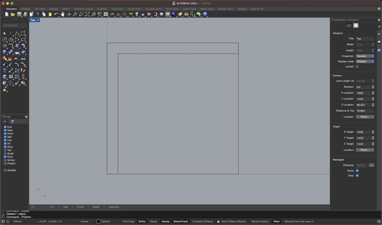
Starting with a 2D Drawing
First, you begin by sketching your design in 2D. This is like making a blueprint of your object. You can use Rhino's various drawing tools to create precise lines, curves, and shapes. For instance, you might draw a simple rectangle, circle, or a more complex freeform shape, depending on what you need for your final 3D model.
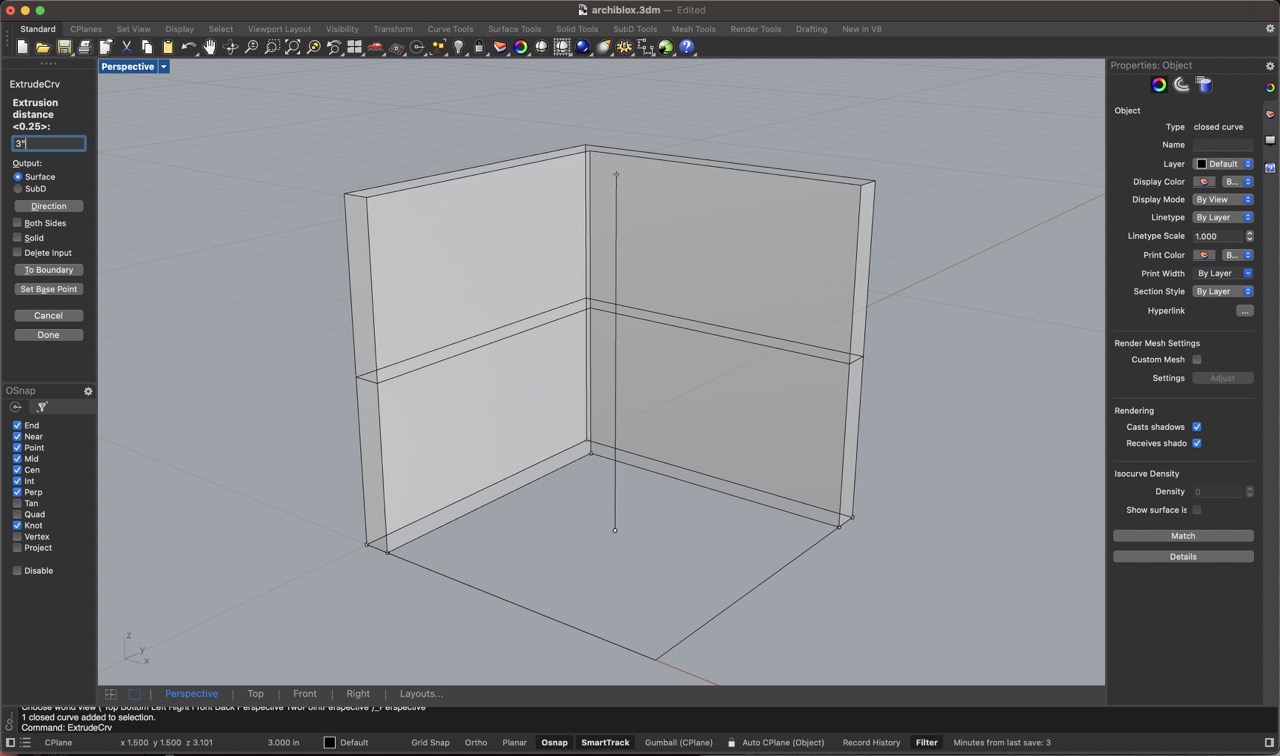
Extruding Curves
Once you have your 2D drawing ready, the next step is to give it depth by extruding the curves. Think of this as pulling your 2D shape up into the third dimension. In Rhino, you select your 2D curve and use the "ExtrudeCrv" command. This command will allow you to specify how far you want to extend your shape upwards (or downwards), turning your flat drawing into a 3D object.
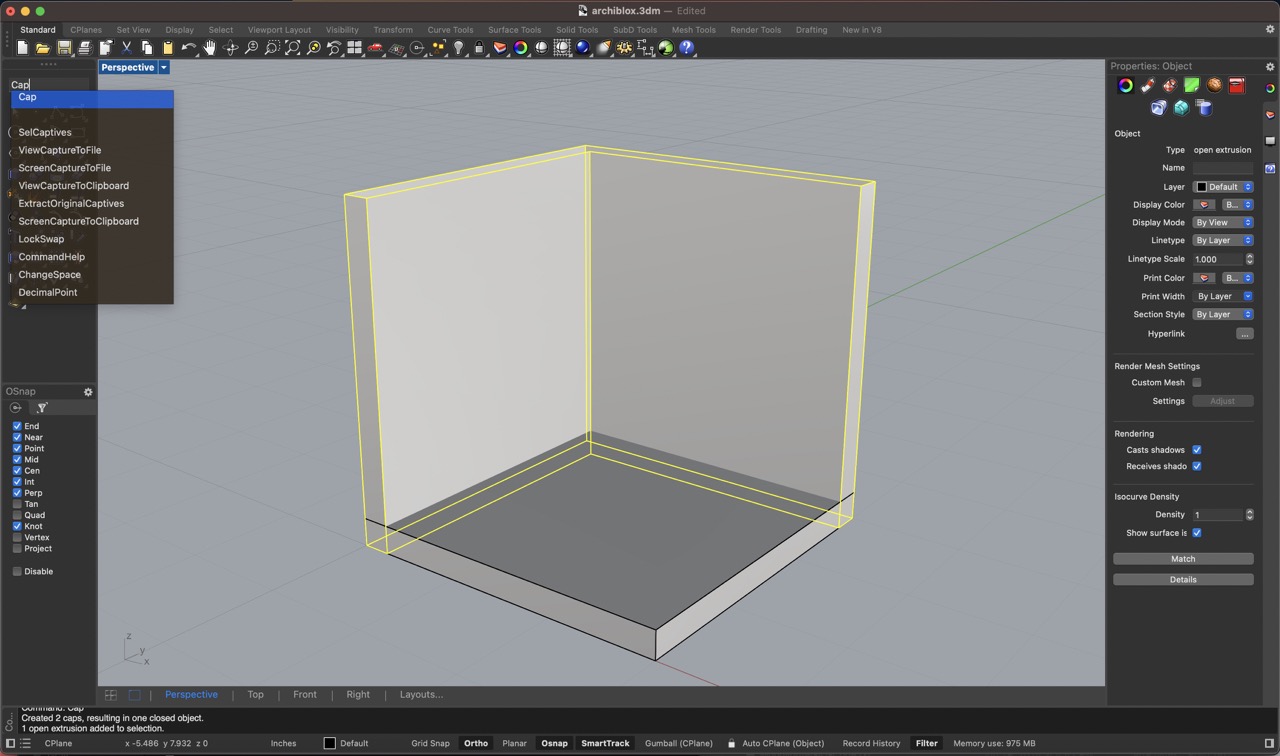
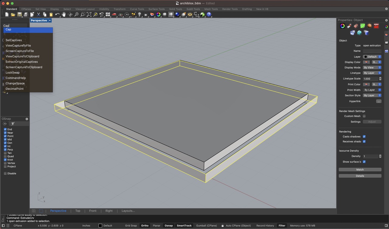
Capping the Volumes
After extruding, you might have an open-ended shape. For example, if you extruded a circle, you'd have a cylinder that's open at both ends. To close these openings, you use the "Cap" command. This command will automatically add surfaces to close off the ends, making your object a solid volume.
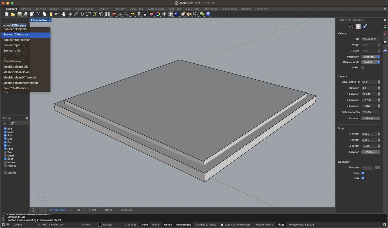
Using Boolean Commands
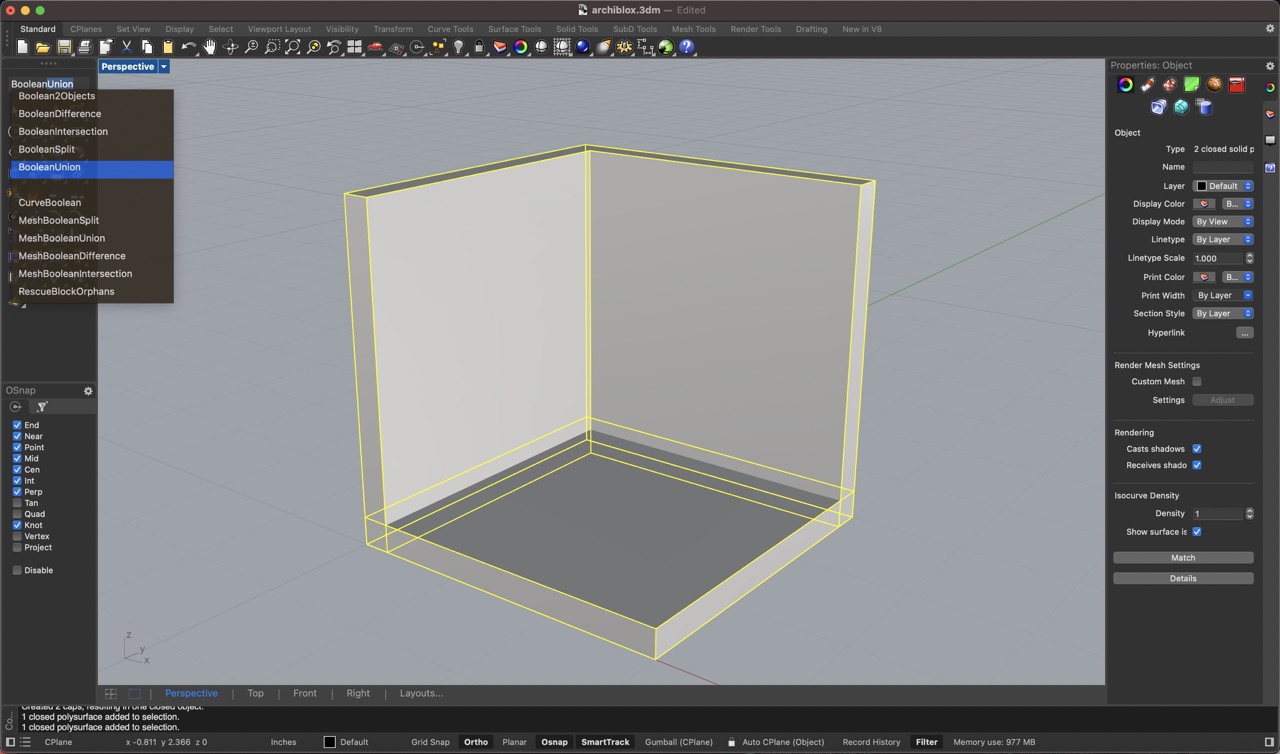
Now that you have solid 3D shapes, you can start combining them to create more complex forms. Rhino provides Boolean commands for this purpose:
- BooleanUnion: This command allows you to combine two or more shapes into one solid object. For example, if you have two overlapping cylinders, you can merge them into a single shape.
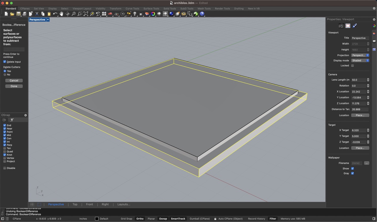
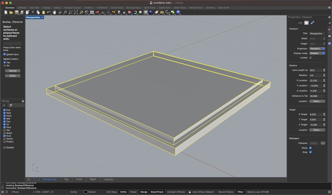
- BooleanDifference: This command subtracts one shape from another. So if you have a cylinder and a cube, you can use the cylinder to cut a hole through the cube.
- BooleanIntersection: This command creates a new shape from the intersecting volume of two shapes. Imagine two overlapping spheres; the intersection command will give you the shape where they overlap.
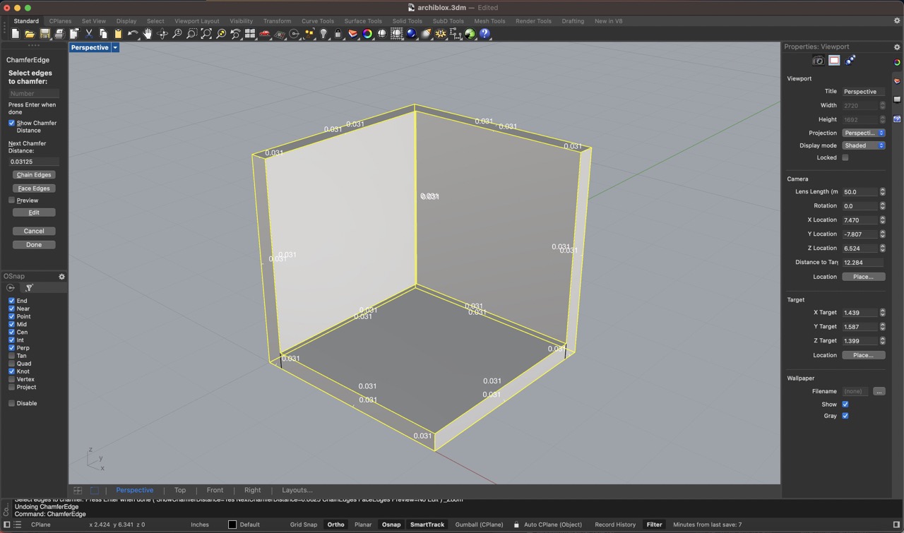
Creating Beveled Edges with "ChamferEdge"
To add some finesse to your model, you might want to create beveled edges. This is where the "ChamferEdge" command comes in. A chamfer is like a flattened corner or edge.
1. Select Edges: First, you select the edges you want to chamfer. You can do this by clicking directly on the edges of your 3D model.
2. Specify Distance: Next, you specify the distance of the chamfer, which is how much of the edge you want to bevel. Rhino will prompt you to enter this distance.
3. Execute: Once you've set your distance, execute the command, and Rhino will create the beveled edges along the selected edges of your model.
From a simple 2D sketch to a detailed 3D model with chamfered edges, Rhino3D provides powerful tools to bring your designs to life.
Designing the Archiblox Prototype on Rhino 3D
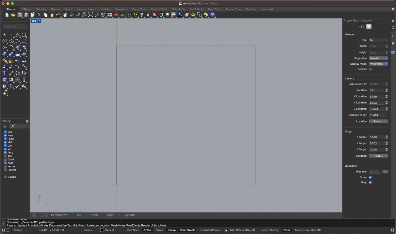
Polyline Command - 3" x 3" Tile
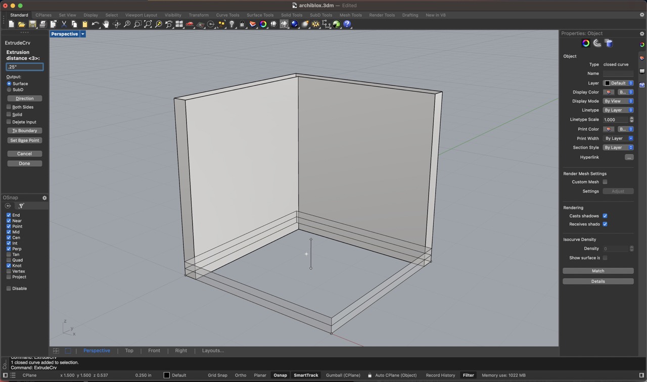
ExtrudeCRV Command - Walls
ExtrudeCRV Command - Floor
CAP Command - Walls and Floor
Boolean Union Command
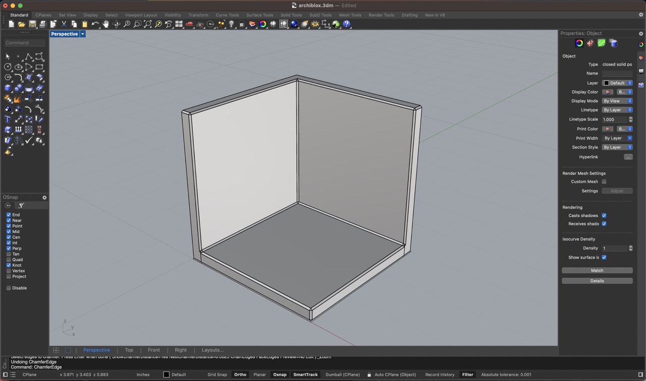
Chamfer Edge Command
Finished 2-Wall Tile
Polyline Command - 12" x 12" Board
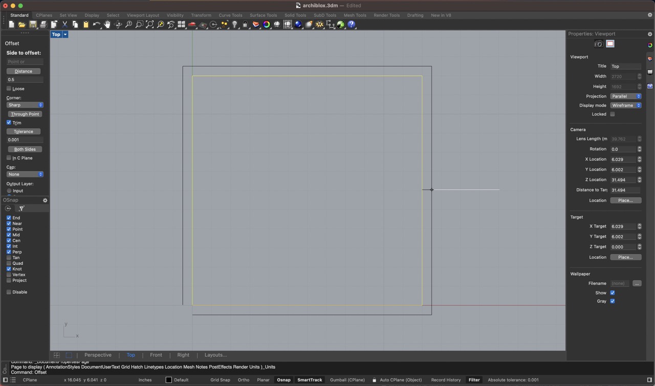
Offset Command - Border Walls
ExtrudeCrv Command - Base 1/2"
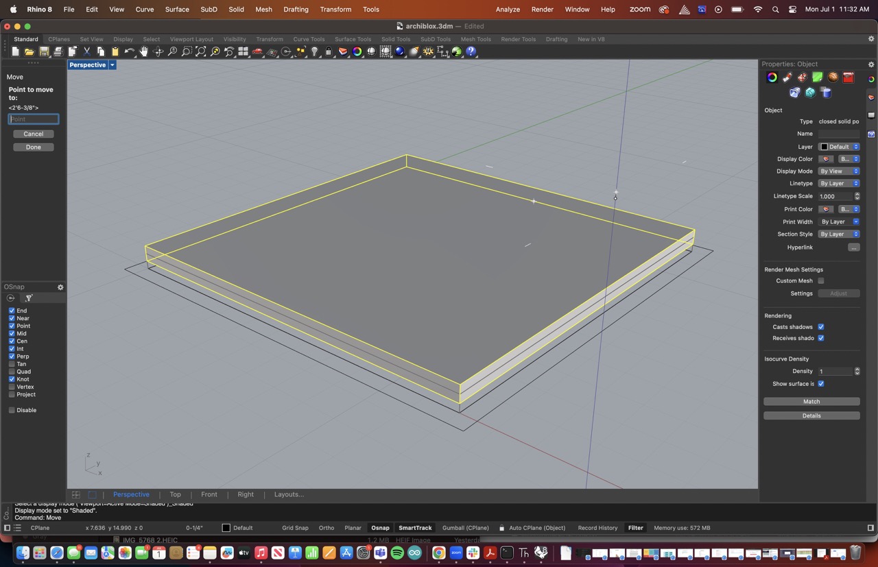
Move Command - Up 1/4"
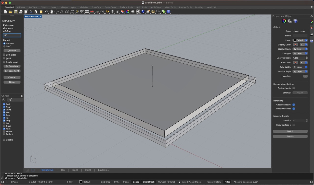
ExtrudeCrv Command - Walls 1/2"
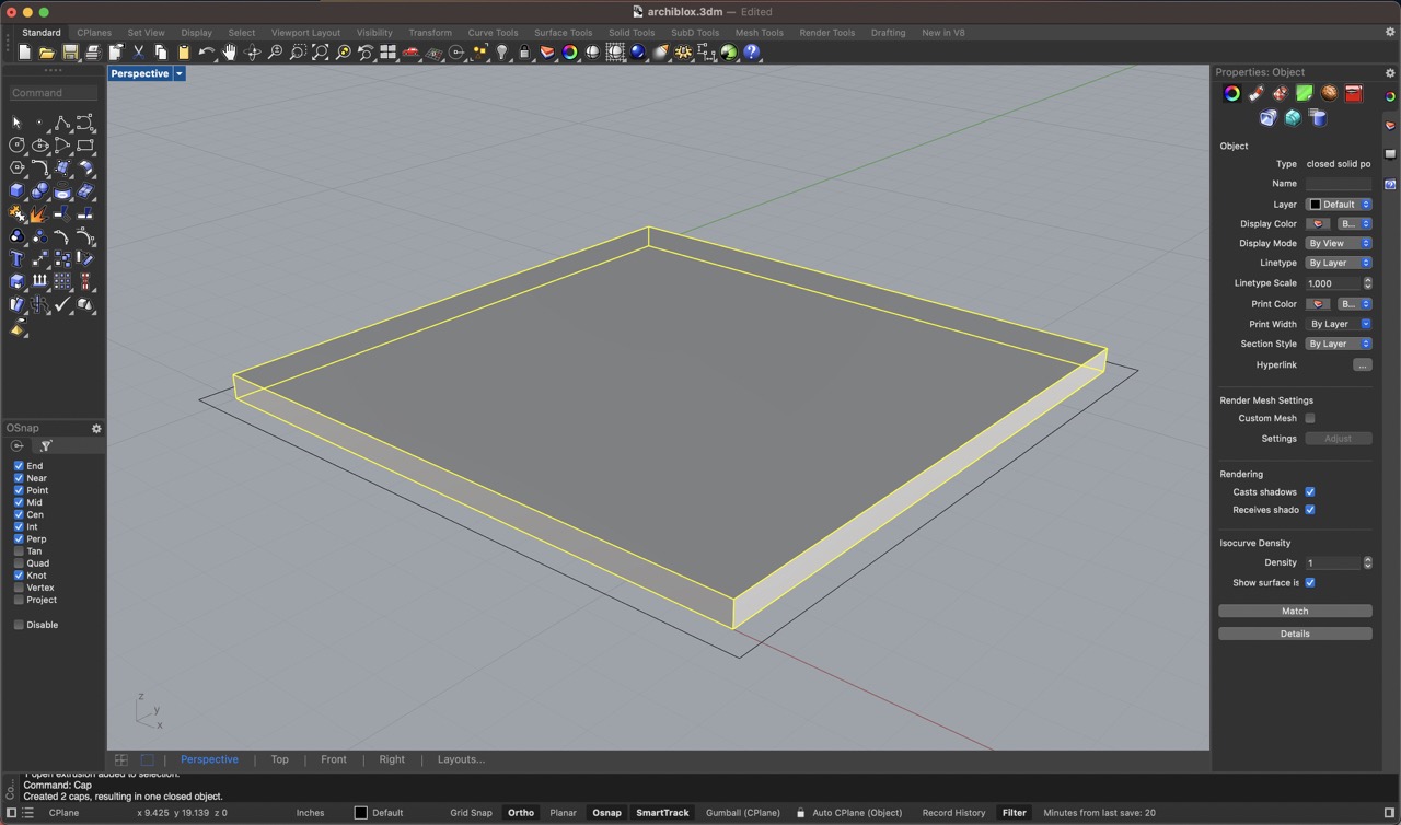
CAP Command - Base and Walls
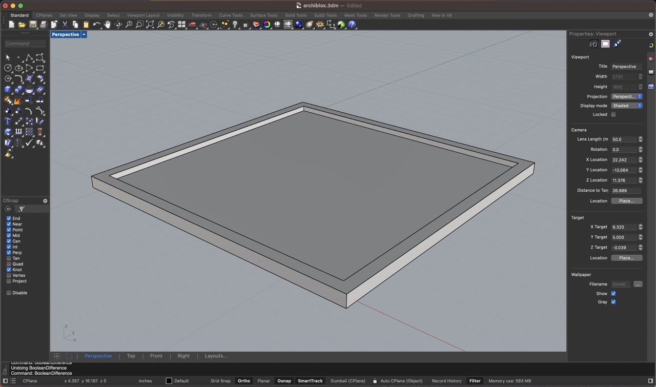
Boolean Difference Command
Boolean Difference Command - From Walls
Boolean Difference Command - With Base
Finished Boolean Operation
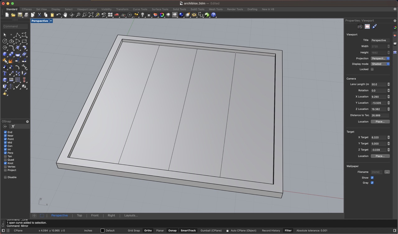
Line Command - For Grid Etching - Midpoint to Midpoint Snap
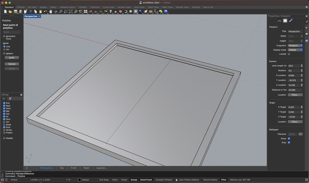
Line Command - For Grid Etching - Midpoint to Midpoint Snap
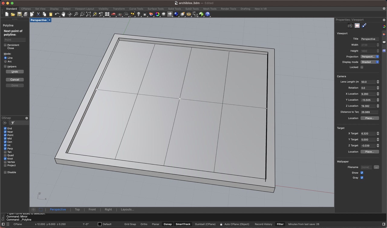
Mirror Command Using Midpoint
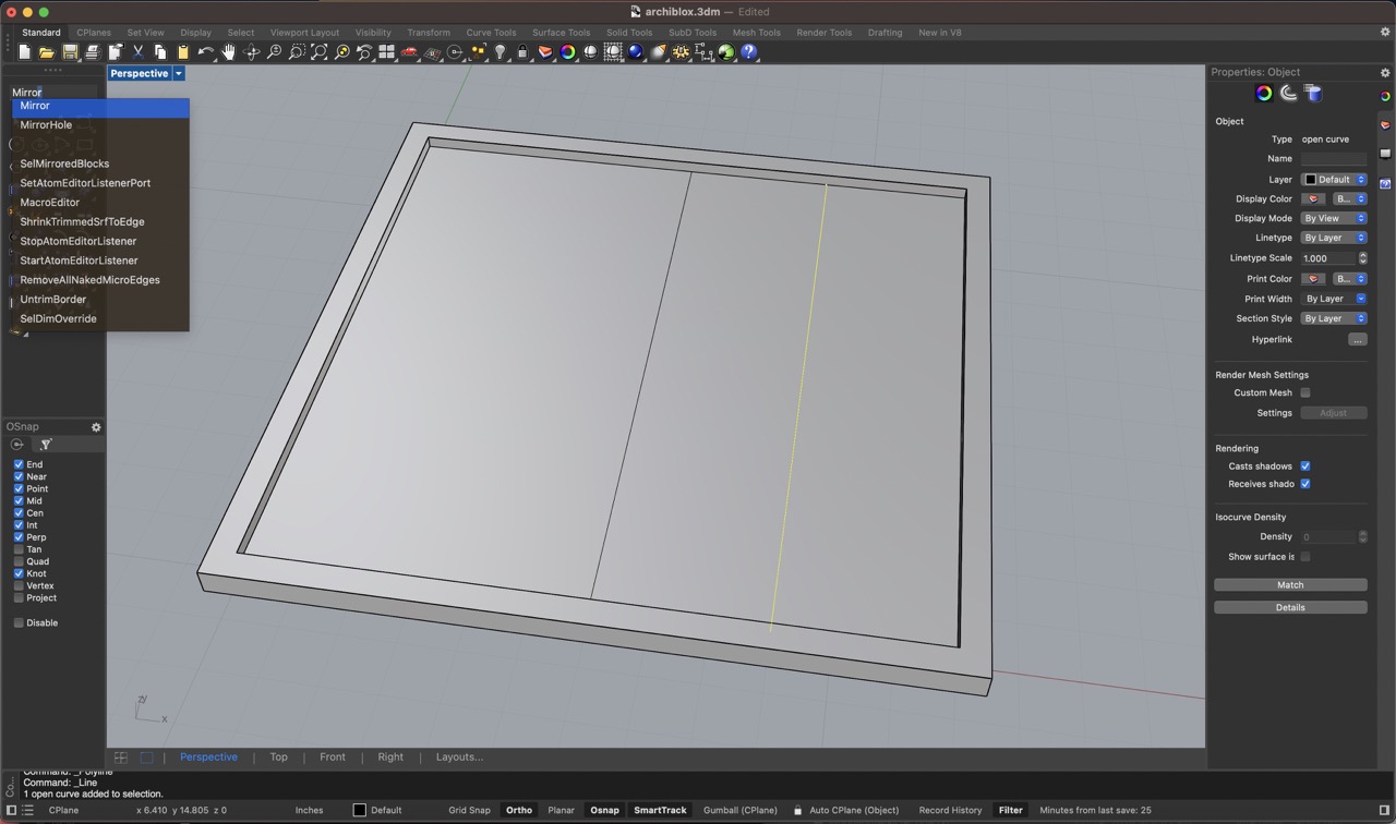
Finished Mirror Command
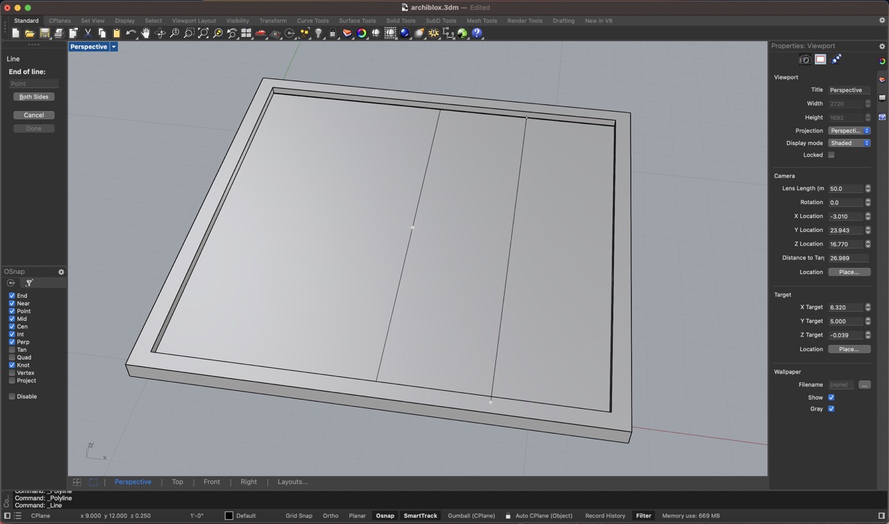
Polyline Command - Midpoint to Midpoint Perpendicular to Original Axis
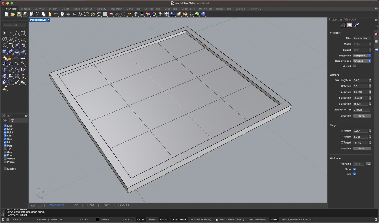
Offset Command 3" - From Both Sides of Center Line

Finished Game Board
I repeated these procedures to create the One Wall Tile, Three Wall Tile, and Four Wall Tile.
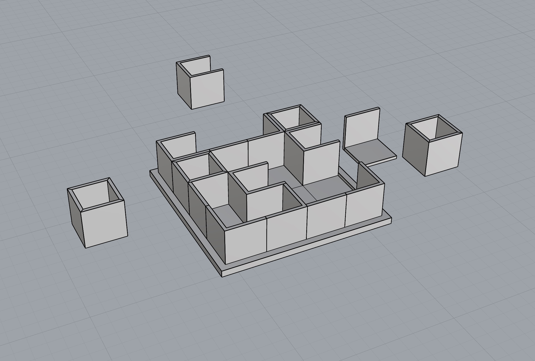
Most common commands used: polyline (to make the 2d sketch), extrudecrv (to make the volume), cap (to make it a watertight enclosure), booleanunion (to combine multiple volumes), booleandifference (to carve one volume from the other).
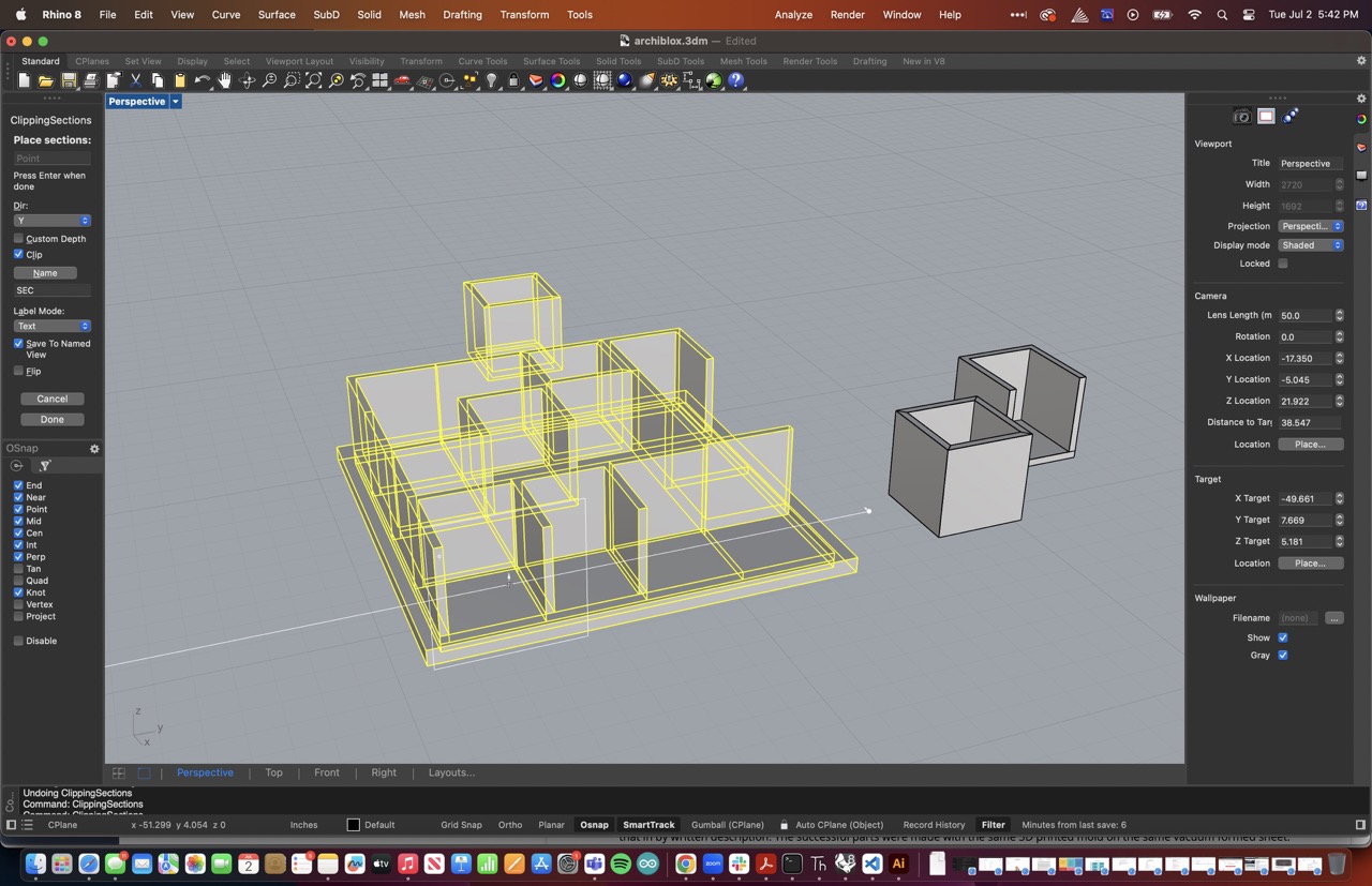
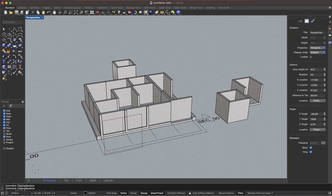
Clipping Plane
I used the 'clipping section' plane command to cut through the model and the 'make2d' command to get the lines. Export the lines as a .dxf
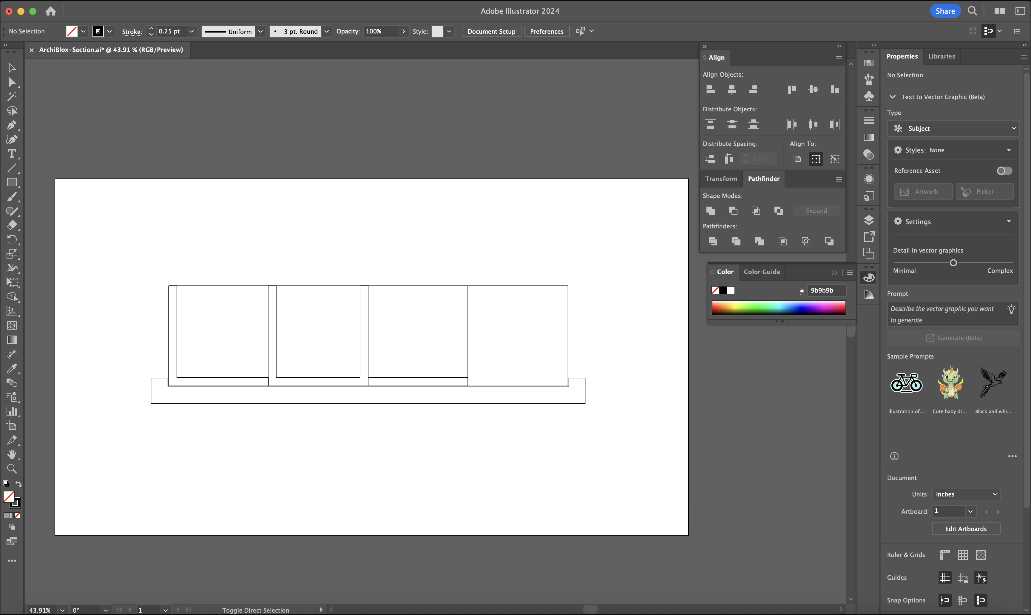
Making a Clean 2-D Section Drawing in Adobe Illustrator
The idea is to import the vector lines into illustrator in order to improve the line weights, color fills, and dimension style for my section drawing.
Step 1: 'Place' .dxf Lines
Import the lines from the .dxf exported from Rhino
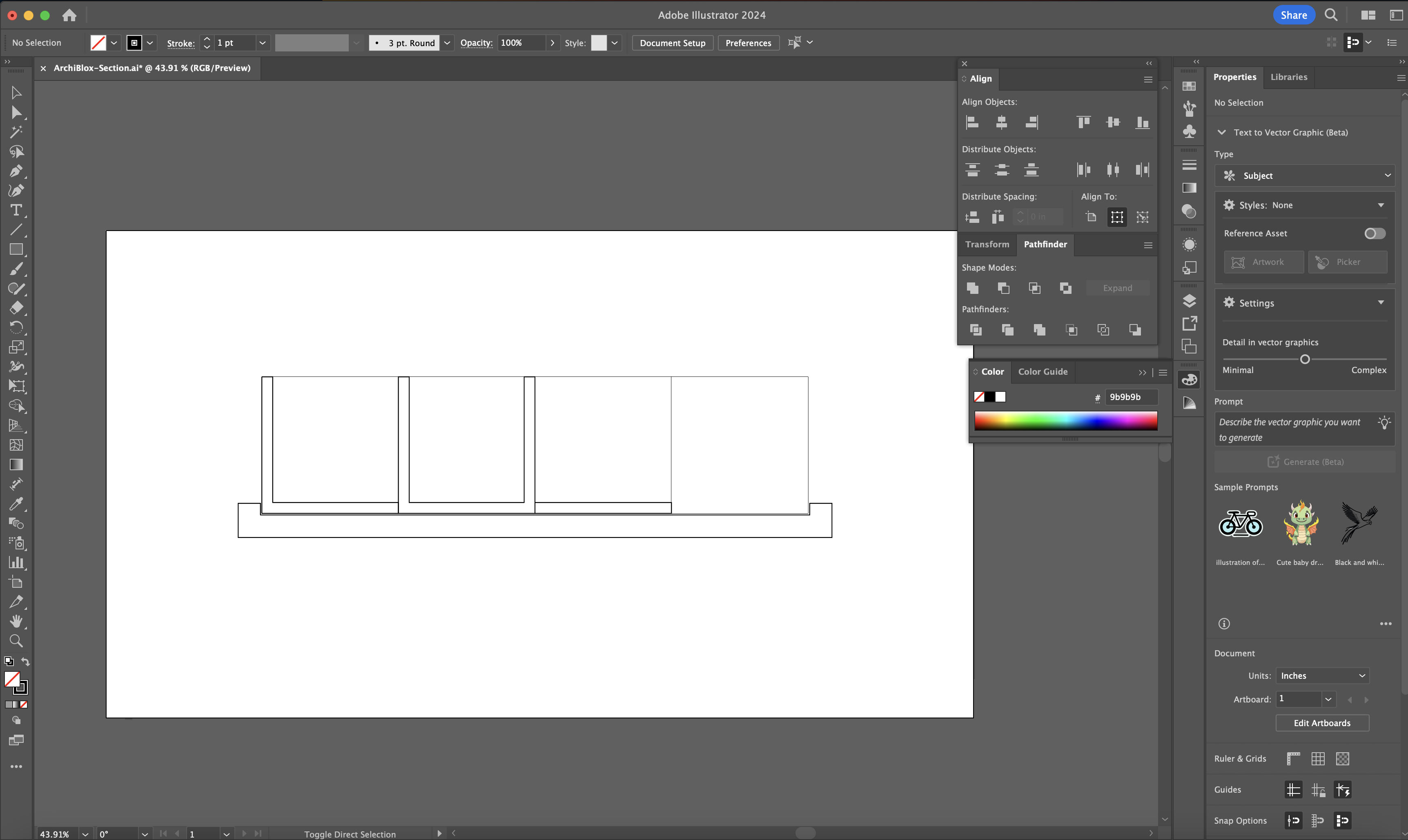
Step 2: Select All of The "Cut Lines"
Selecting the lines that are cut by the plane using the white selction arrow tool.
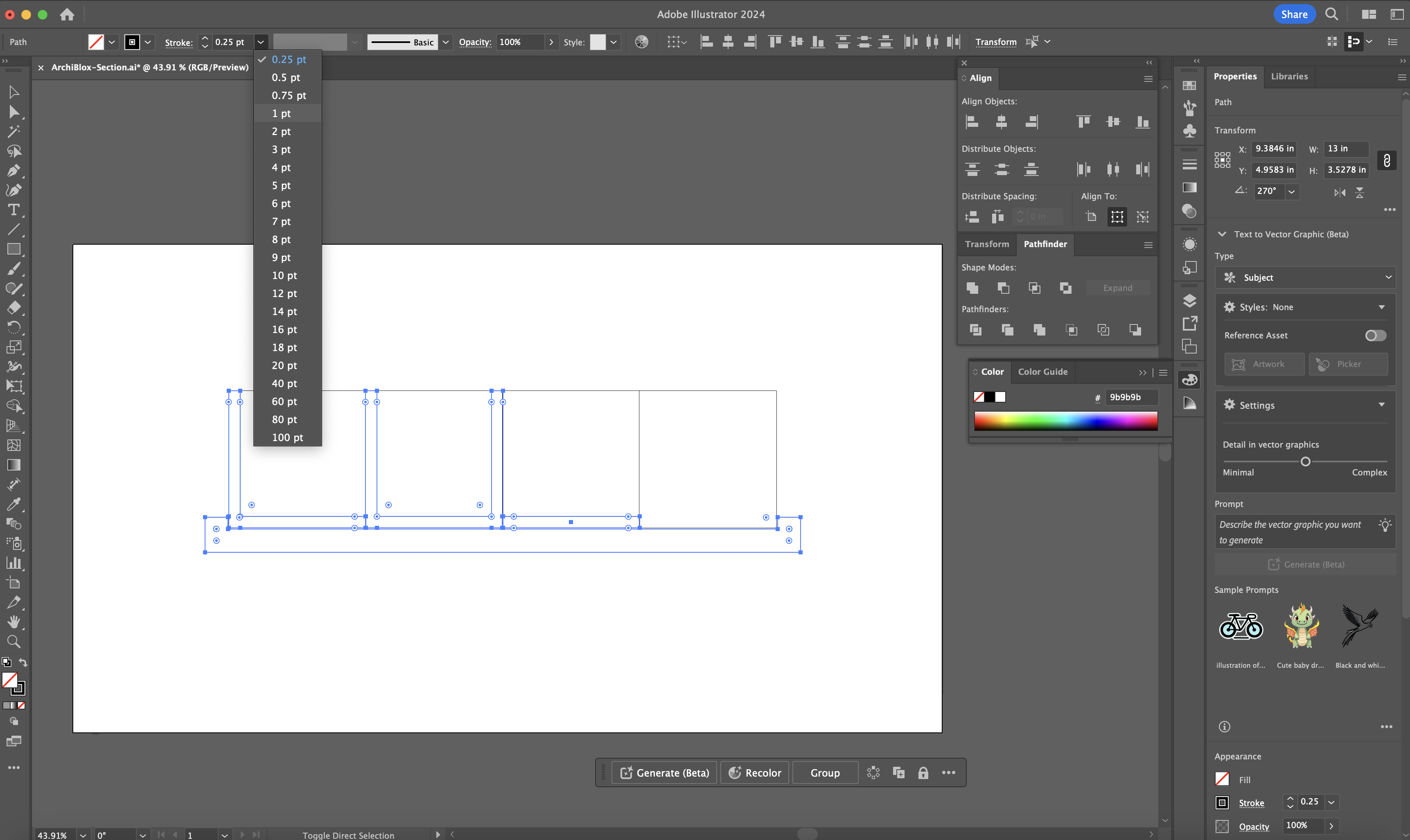
Step 3: Change Line Stroke to a Thicker Point
Select a stroke weight that contrasts with the other lines in the drawing. I selected 1pt. because all of the other lines are .25 weight.
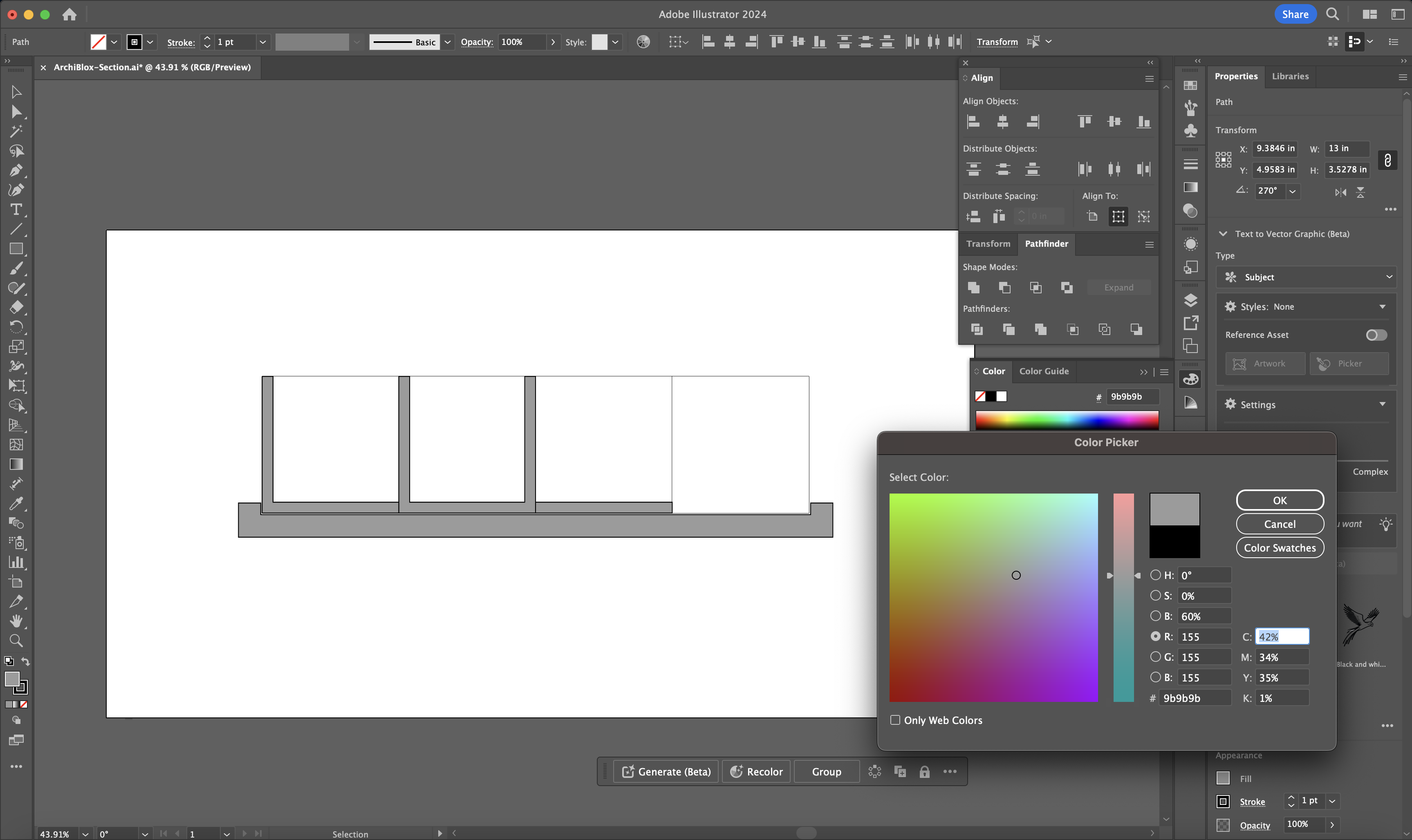
Step 4: Adding a Fill
Select the lines that connect each cut section and right click and select "JOIN" so that it forms a closed polyline group. Then click on it and select the fill color from the color tool on the bottom left. I used a medium gray to represent the poché.
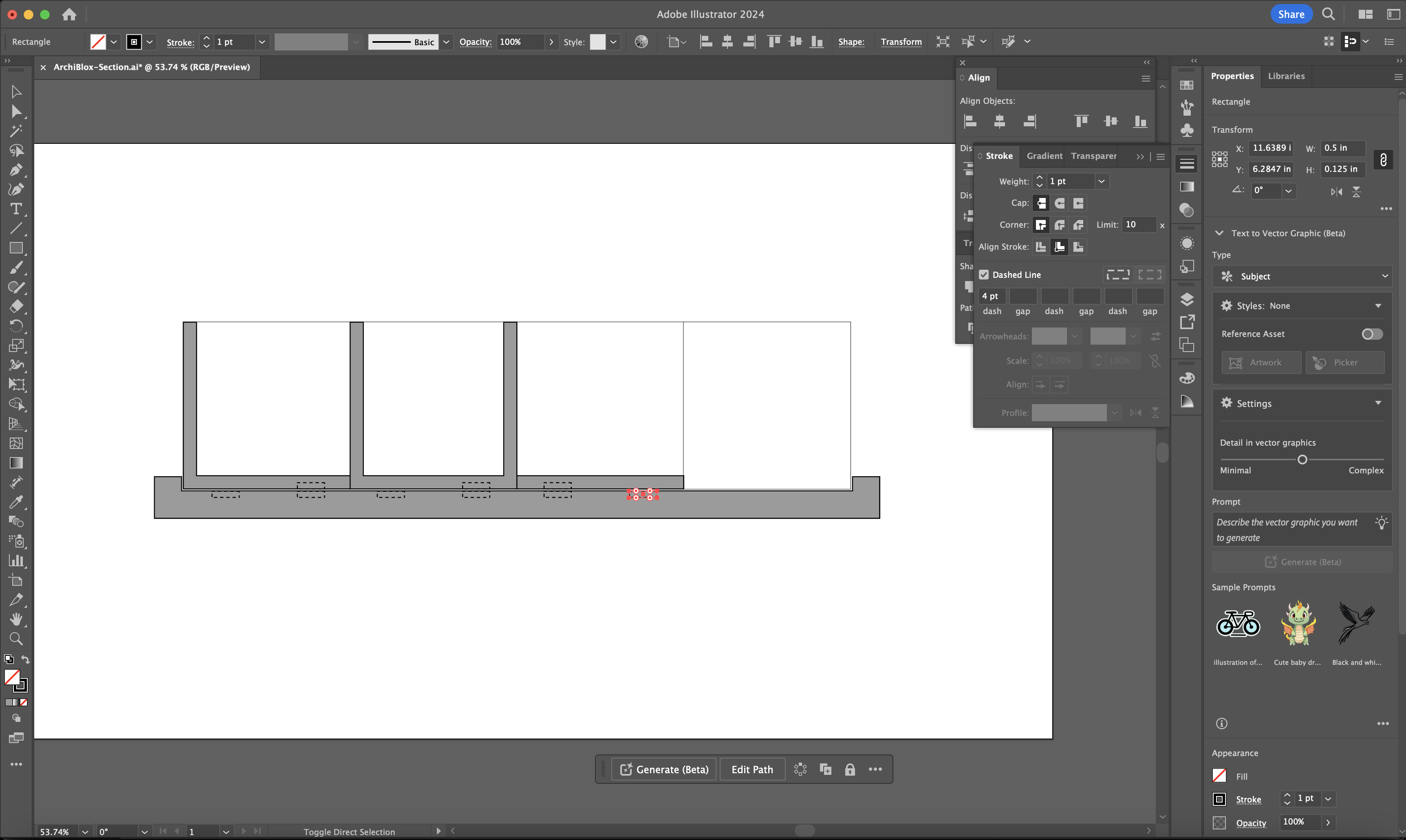
Step 5: Creating Diagrammatic "Hidden Geometry"
To represent the magnets and sensors that would be embedded in the form, I used the rectangle tool to create small boxes in the cut section area. I clicked the "dash" line check box to make them dotted lines to represent the fact that they are hidden elements.
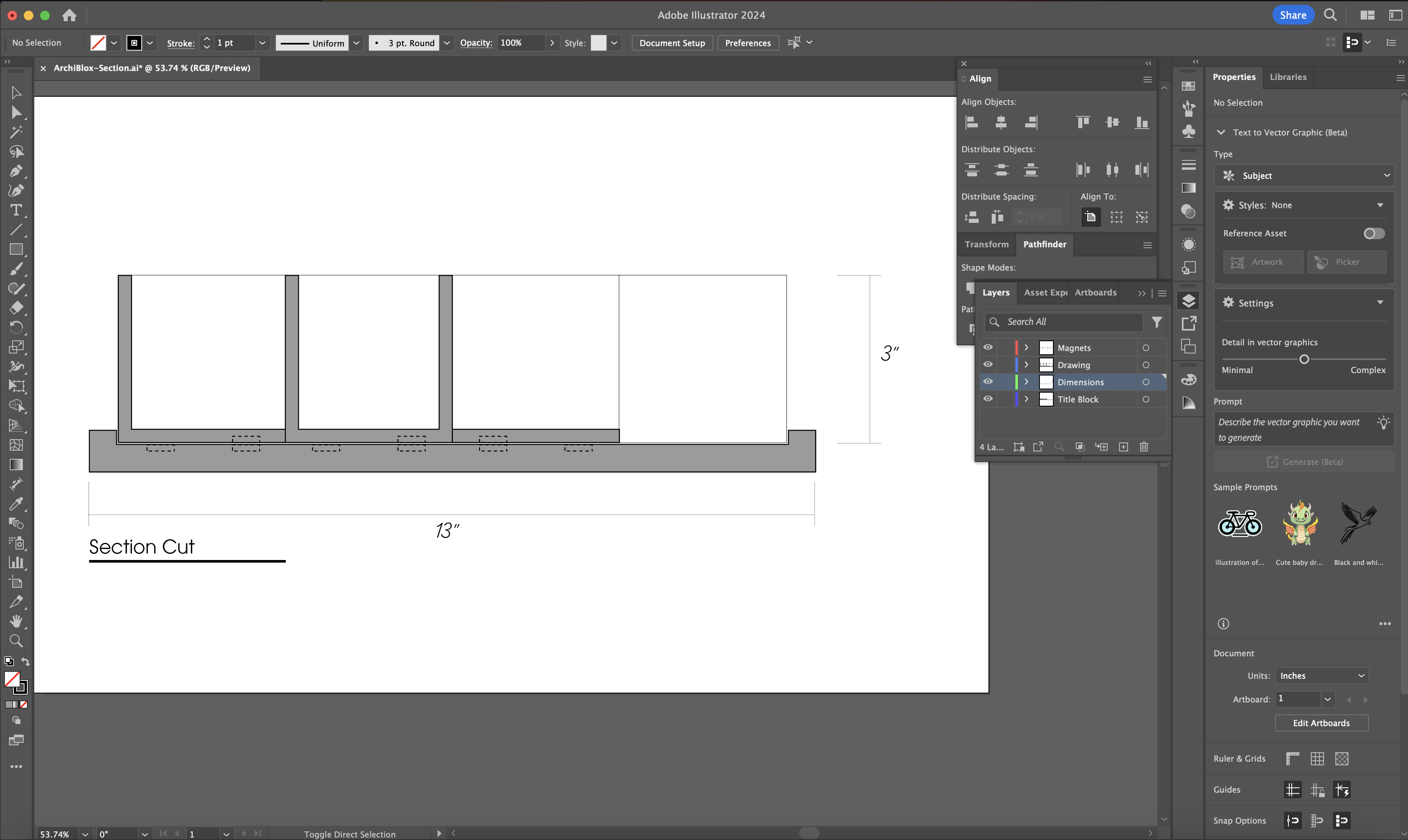
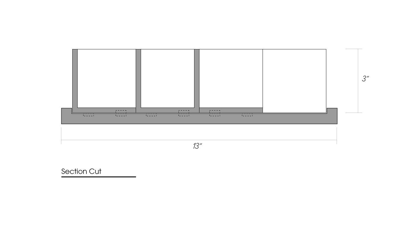
Step 6: Adding Dimensions and Title Block
I added lines that align with the outer dimensions of the board and the tiles and used the type to add numbers to represent the dimensions. I added the 'Section Plane' text at the bottom left to title the drawing.
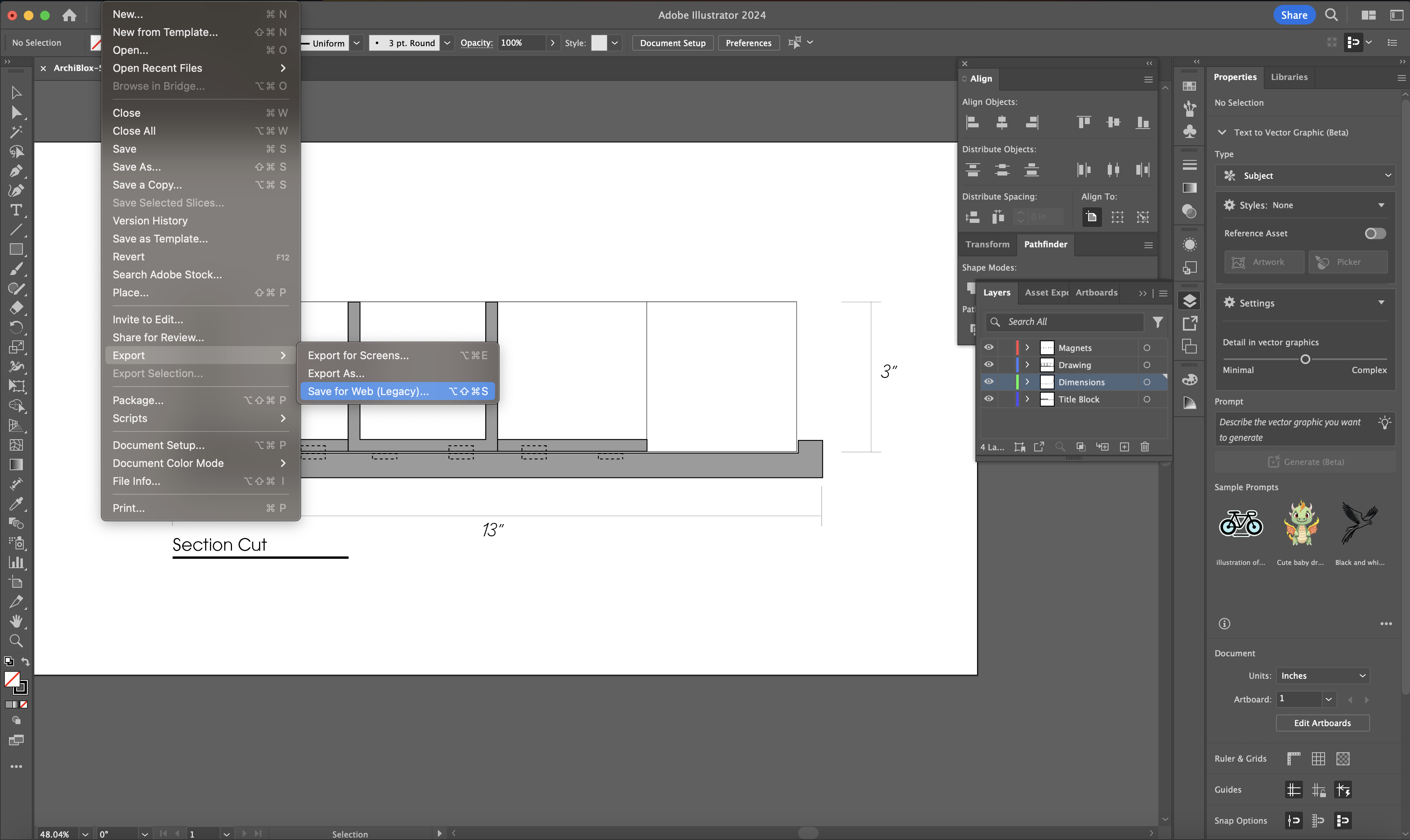
Step 7: Export As - Export for Web
In order to save a compressed image that retains quality, I use the export for web option to save the image.
Final Section Diagram:
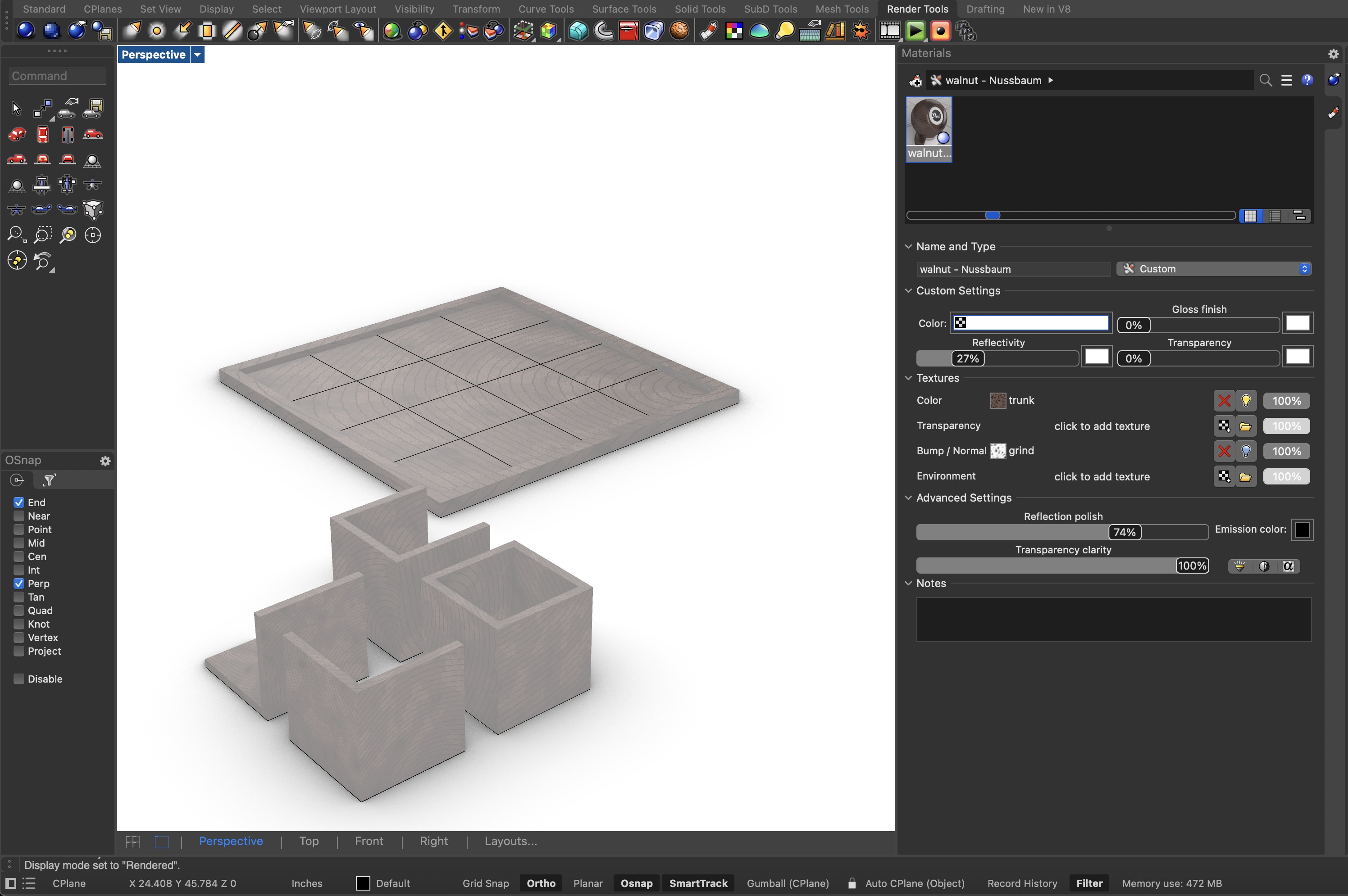
3D Rendering
I then returned to Rhino to utilize the rendering capabilites. I found some great wood materials on Food 4 Rhino and used the mahogonay finish in the material panel.
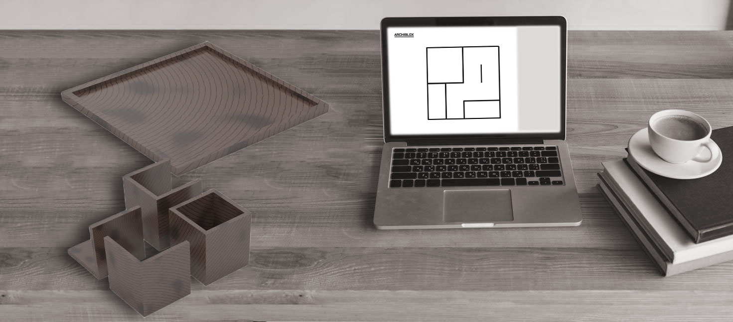
"Digital Collaging" a Realistic Rendered Image
After exporting the perspective rendering from Rhino, I found an image online resembling a desk with laptop computer and added the rendering atop the desk to give the appearance that it was sitting next to the laptop. To add a bit of depth and realism, I made a duplicate of the rendered object and masked it with a black fill, moved the layer under the rendered image, shifted it left to match the shadows of the other objects in the image, and used 'gaussian blur' to cast a show of the object on the desk. I then added the vector floorplan diagram I created in week one on the screen of the laptop to reflect that the game board can wirelessly communicate a floorplan to the digital interface.
Final Rendering:
Files
Download 3D Model Download Illustrator File
Copyright 2024 Thomas Pupo - Creative Commons Attribution Non Commercial.
Source code hosted at fabcloud/fabacademy/2024/thomas-pupo