Design and document the system integration for your final project
This week I was so happy we had the chance to build the system integration for our project because there was a lot of work for me to do in this case. In general this project broke down to three simple systems:
Chassis
Head Unit
Body Unit
Bowtie Unit
Head Control Gear
Sensing
"People" Sensor
Output
Servo: Bowtie Actuation
Motor: Head Actuation
Screen: Emotive
Power
A Breakdown of the Chassis
Currently the Chassis of the DAPR unit is broken into 4 major components not including motors/servos/circuits
This video breaks down the units and is only missing the circuits that I need to rework to be something viable.
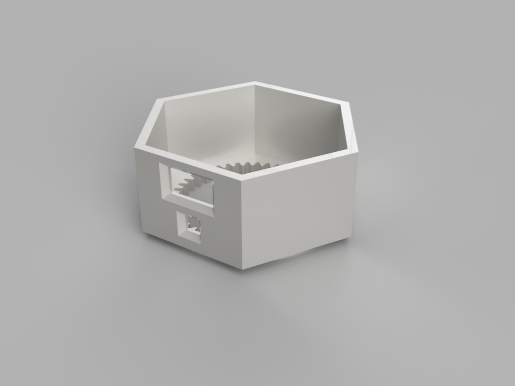
The "Head"
This unit will house one input unit and one output unit. The larger hole on the top will hold the screen that you can see in action in Output Week. It will be for emotive interaction and will communicate with the user by making facial expressions.
This also houses the input camera, a "Person Sensor" that creates a bounding box around a persons face and will let DAPR follow them visually. Trying to center the person sensed into a bounding box.
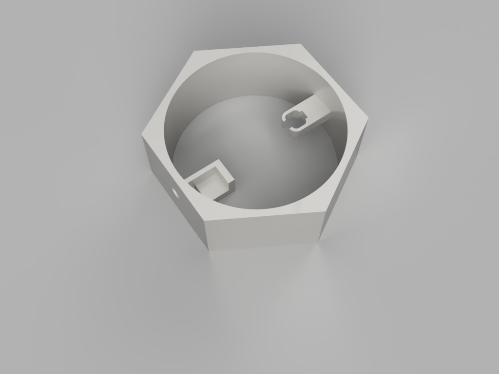
The "Body"
The body will house most of the movement units of DAPR. The head controlling motor which is a small scale N20 Motor. It also holds the most important servo. The Bowtie Control Unit! This unit will assist in emoting for the robot and allow the bot to have a few idle animations if no person is detected.
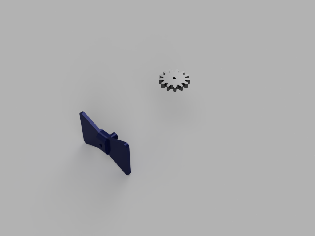
The Control Gear and Bowtie Unit
Both of these smaller units will be held internal to the robot and allow for motion and emotion. THe bowtie unit will wiggle if a person is seen and the gear will be attached to a small motor that will let the head follow a person.
Electrical: Aka What I need to rework
Currently I had a chip in v3 that is designed to work for the electrical for two motors a servo and one sensor. But this was designed for a previous version of the robot. Currently I am working on changing how DAPR works so that the robot will not hit the problems of the lazy susan where cables get tangled and create a mess for everything.
The Idea:
My current idea is to create a two tiered chip system that will minimize the movement of cables as well as adding a physical stop to rotation so that it will not rip cables should someone want to move in circles around DAPR's head.
A simplified description of what I thing I will do is broken into the two units, head and body.
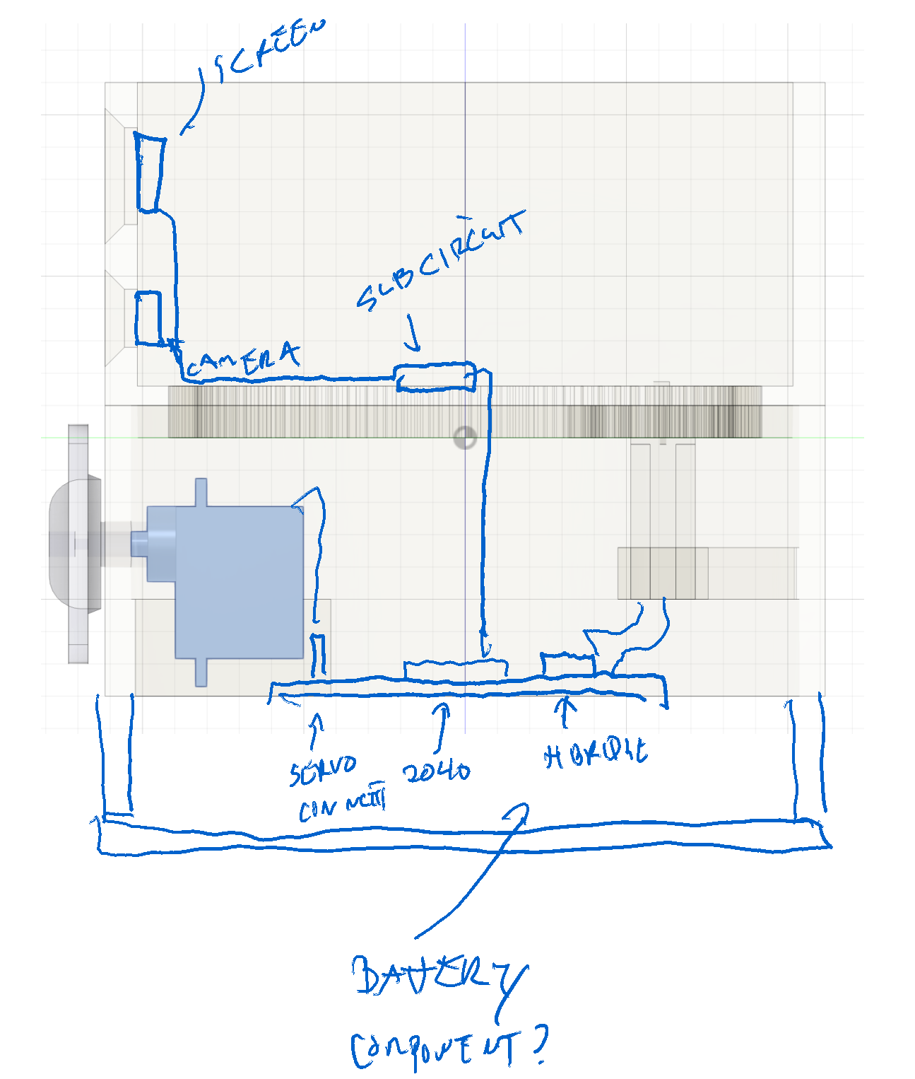
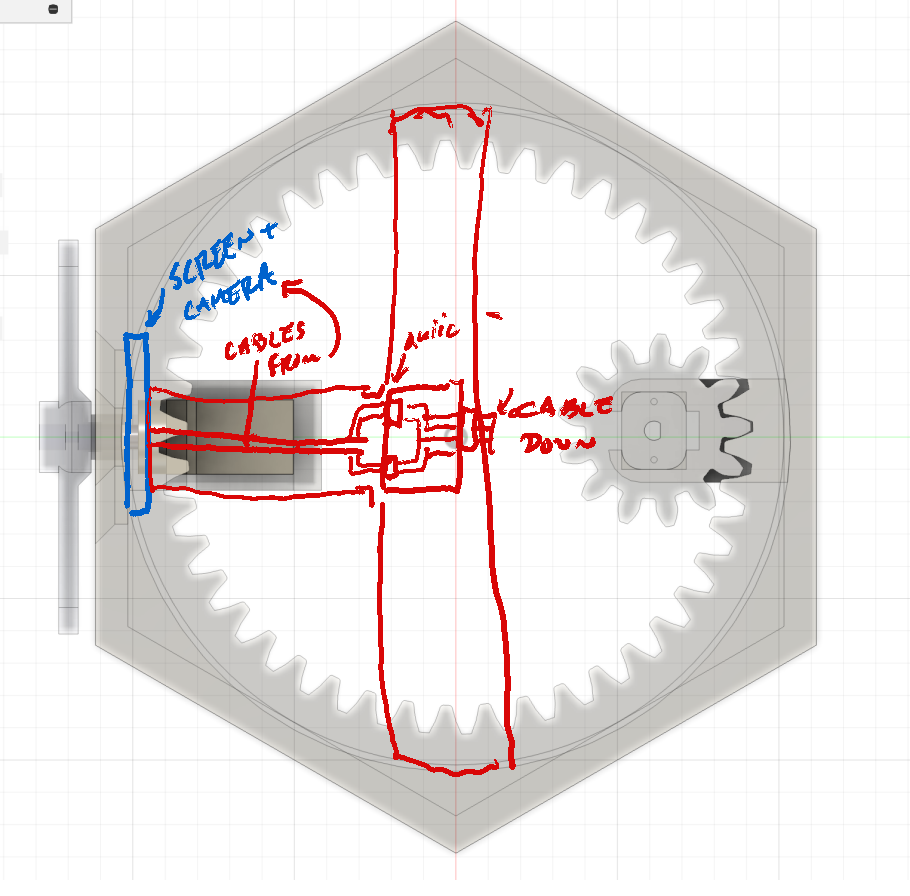
Head Electrical
All of my circuit components use I2C because of this I am considering using the Qwiic connector system. I will be connecting both the screen and the camera to a central chip that will be fastened to a bar that is sitting across the center of the head.
This will then have one cable that is dropped down to the main board in the body unit since that should be stationary.
Body Electrical
The unit in the body will hold the control chip (A XIAO RP2040) an HBridge for the motor and the connects for the servo as well as the receiving cable for the upper board.
Right now, the idea for power is that it will be provided by a rechargable power bank that fits within the chassis. I have not calculated the total Watts pulled by the system so I will have to do that to be sure the battery and RP2040 can handle them all.
Bill of Materials
The final process I needed to do was break down the parts I needed for this project. So a general breakdown of this is below