Group Project
The RP2040
For this week I decided to keep coding on the QuenTorres system. On my board there is the SEEED Studio XIAO RP 2040
As it says in the name the SEEED XIAO has an RP 2040 chip at the core of it. If you go to the XIAO website there are actually different architectures the board can come in including one with the ESP32 architecture that I may go back to to be able to use its "sense" version with the camera. I want my final project to detect a person and then greet them for the lab as well as have voice activation connected to a possible Alexa API. But for now I stick to the 2040.
The chip itself has some interesting capacities seen in its summary page on the documentation in page 11. These are listed as:
- Dual Cortex M0+ processor cores, up to 133MHz
- 264kB of embedded SRAM
- 30 multifunction GPIO
- 6 dedicated IO for Flash
- Programmable IO for extended peripheral support
- USB 1.1 Host/Device
Though a lot of this is jargon some of the things that stand out to me are the 30 GPIO pins and the 264kB of ram. The chip I am most accustomed to, the Arduino UNO has only 2kB of SRAM and the RP has a significant jump from this allowing for a lot more experimentation. The 30 GPIO pins also beats the UNO by 10 which allows for a lot more experimentation throughout.
The Esp32s3
This is a different architecture that Tom used for his project Archiblox. It seems to a lot more leaning towards IoT over stronger processing. It has an excellent feature of having actual connectivity to the internet and wireless communications with a Wifi Module and the Bluetooth LE communication to be able to connect to peripherals.
I feel like if I want my project to connect to the internet this might be a better option, some highlights of the data sheet are:
- dual-core processor running up to 240 MHz
- 523KB of SRAM versus the RP2040s 264kB and support for external memory
- 2.4 GHz Wifi and Bluetooth 5
- 45 GPIO with multifunction
- Programmable IO
Comparing the two architectures
While the RP2040 is better with simpler work and is easier to code in Arduino C where the ESP32 can be coded in C but is harder to connect to this.
Both of these architectures use microPython and can be coded easily in this though the chip must be flashed to work properly like this.
In short I think for astandalone system the RP2040 is easier to use especially with my familiarity of the RP ecosystem, howeveer if I were working on IoT I would use the ESP32 SEEED XIAO
I want to take advantage of all of this for my final project but the SEEED XIAO may not have enough IO for the project I want to do. I have to look into it more closely. If this is the case I will upgrade to the RPi Pico. Or develop my own board using two XIAO in tandem.
The SEEED XIAO
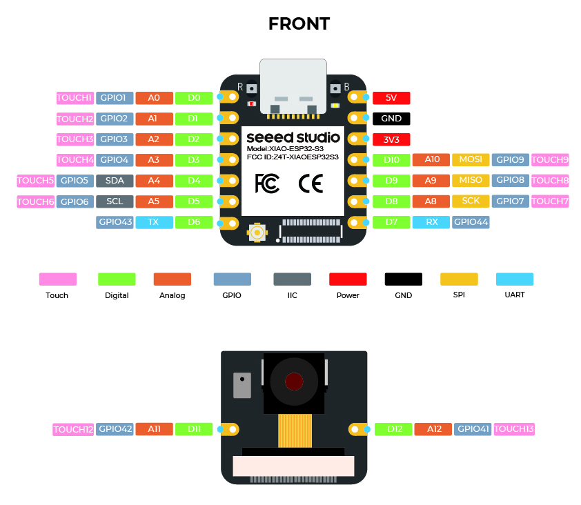
In this assignment the picture I used the most was this one:

More specifically the part with the blue numbers which signified the Arduino GPIO. This would let me know which pins I was going to take advantage of to be able to code the board properly. This and the following image of the QUENTORRES chip helped me program everything I needed to.

In this image I found the number of the pin from the first image and followed the outputs to figure out what each of the headers would lead to and how I could program the chip.
How I Started Coding:
It is never wise to just start from scratch when you are learning something new. The world has already advanced in so much one might as well use what is out there to get started. So in my case I used the code that was uploaded by Neil in this week's class to start my code.
Wait a second I have to set up my chip
The first thing I noticed after trying to upload simple code to my chip is that the Arduino IDE does not automatically detect an RP2040. So luckily the great people at FabAcademy have the QuenTorres documentation to help you with this. I followed the steps in the portion defined How to use as a hello board. I followed these steps and then was able to upload the "Blink" program from Arduino and noticed there was already a problem...
In short these steps tell you to:
- Open the Arduino Program and add Arduino-Pico by Earlphilhower to File-> Preferences of the additional boards manager
- Go to download Pico in Tools->Board->Board Manager
- Configure the Arduino IDE for a SEEED XIAO RP2040
- Load the Blink Program from File->Examples->01.Basics
If you follow this perfectly, it will not work... Reason being. The LED and Button on the Arduino and on the XIAO are in different GPIO. So instead I pivoted and used the code from Neil's site. Specifically the code below:
      //
      // hello.button-blink.RP2040.1.ino
      //
      // Seeed XIAO RP2040 button, blink, echo hello-world, single core
      //
      // Neil Gershenfeld 12/28/23
      //
      // This work may be reproduced, modified, distributed,
      // performed, and displayed for any purpose, but must
      // acknowledge this project. Copyright is retained and
      // must be preserved. The work is provided as is; no
      // warranty is provided, and users accept all liability.
      //
      // add RP2040 core
      //    https://github.com/earlephilhower/arduino-pico
      //

      #define led_pin 1
      #define button_pin 0

      void setup() {
         pinMode(led_pin,OUTPUT);
         pinMode(button_pin,INPUT_PULLUP);
         Serial.begin();
         Serial.setTimeout(10);
      }

      bool button_up = true;

      void loop() {
         if (Serial.available()) {
            digitalWrite(led_pin,HIGH);
            String s = Serial.readString();
            Serial.print("you typed: ");
            Serial.println(s);
            delay(100);
            digitalWrite(led_pin,LOW);
         }
         if ((digitalRead(button_pin) == LOW) && button_up) {
            digitalWrite(led_pin,HIGH);
            Serial.println("button down");
            button_up = false;
         }
         else if ((digitalRead(button_pin) == HIGH) && !button_up) {
            digitalWrite(led_pin,LOW);
            Serial.println("button up");
            button_up = true;
         }
      }
Then nothing happened!
When you inspect the code you can see that the buttons will be lit up and then if you press the button they will turn off (as well as when you type something into the Serial Monitor on the system it will reply with your input.) but nothing happened. I was wondering why there was nothing happening. Then I inspected the code a little and the problem was here:
        #define led_pin 1
        #define button_pin 0

        void setup() {
          pinMode(led_pin,OUTPUT);
          pinMode(button_pin,INPUT_PULLUP);
          Serial.begin();
          Serial.setTimeout(10);
       }
The #define
This part of the code sets two variables led_pin and button_pins to the values of 1 and 0 respectively. This goes back to the top where we spoke of the GPIO pins. If you look at the SEEED XIAO we have and the circuit diagram. The pins labelled 1 and 0 are both connected to things 1 is indeed connected to an LED. So that can stay in place but 0 is connected to another LED. So no matter how much I touched it, it would not be pushed sadly so I had to look back at the diagram and see what was attached to the button. In this case the TOP LEFT pin is connected to our button, which in this case is GPIO 27. So making a quick swap should fix the problem. Now our code looks something like this:
        #define led_pin 1
        #define button_pin 27

        void setup() {
          pinMode(led_pin,OUTPUT);
          pinMode(button_pin,INPUT_PULLUP);
          Serial.begin();
          Serial.setTimeout(10);
       }
With this small fix, the bottom left LED interacts! But let's be honest, that was boring. I wanted them all to light up so what I did was I found out what pins connected to the other two LEDs and got to work. Looking through the diagrams and code the other two LED Pins are
void setup{} and Output pins
Arduino code in general comes in three sections. The first part is the setup of variables. You define global variables and call on libraries and different things that will be used across the code. You see this in this code with the #define segments of the code at the top that we have been manipulating to make the LED work. The next section is the void setup{}. In this section you activate the serial port, and set your pins and inputs or outputs. Without this the chip does not know what to do or does not activate its interfaces. Here the example is in this line of code:
        void setup() {
          pinMode(led_pin,OUTPUT);
          pinMode(button_pin,INPUT_PULLUP);
       }
In each of these you see
The final section is the void loop{} in this the chip executes all of the code that is running in the program. To control the LEDs you see two basic functions:
        digitalWrite(led_pin,HIGH);
        digitalWrite(led_pin,LOW);
When the second argument is set to HIGH the pin turns on, when it is set to LOW it turns off. So we need to add two more of these for each of the other LEDs to work as well. When you do this the code looks something like this:
          #define led_pin 26
          #define led_pin2 0
          #define button_pin 27
          #define led_pin3 1


          void setup() {
             pinMode(led_pin,OUTPUT);
             pinMode(led_pin2,OUTPUT);
             pinMode(led_pin3,OUTPUT);
             pinMode(button_pin,INPUT_PULLUP);
             Serial.begin();
             Serial.setTimeout(10);
             }

          bool button_up = true;

          void loop() {
             if (Serial.available()) {
                digitalWrite(led_pin,HIGH);
                //adding code here to test my LEDs
                digitalWrite(led_pin2,HIGH);
                digitalWrite(led_pin3,HIGH);
                String s = Serial.readString();
                Serial.print("you typed: ");
                Serial.println(s);
                delay(100);
                digitalWrite(led_pin,LOW);
                digitalWrite(led_pin2,LOW);
                digitalWrite(led_pin3,LOW);
                }
             if ((digitalRead(button_pin) == LOW) && button_up) {
                //adding servo
                myServo.write(10);
                digitalWrite(led_pin,HIGH);
                digitalWrite(led_pin2,HIGH);
                digitalWrite(led_pin3,HIGH);
                Serial.println("button down");
                button_up = false;
                }
             else if ((digitalRead(button_pin) == HIGH) && !button_up) {
              //adding servo
              myServo.write(170);
                digitalWrite(led_pin,LOW);
                digitalWrite(led_pin2,LOW);
                digitalWrite(led_pin3,LOW);
                Serial.println("button up");
                button_up = true;
                }
             }
What happens here is that all three of the LEDs turn on or off unlike the original code where only one turns on.
All the LEDs are working!
Now, I had gotten everything to work, but had reached a flow state where I wanted to do more. So I started thinking about my final project DAP-R. DAP-R is supposed to be a dapper robot and what defines being more dapper than a bowtie. I wanted to add a bowtie to DAP-R and what better to control a moving bowtie than a Servo. A Servo, in its simplest sense is a motor that can move to very precise locations. I chose to use a 180 degree position servo for this job. Specifically these: RGBZONE 4Pcs ES08MA because I had them lying around.

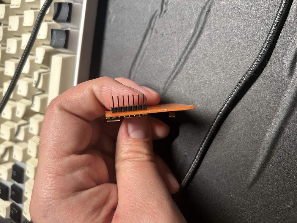
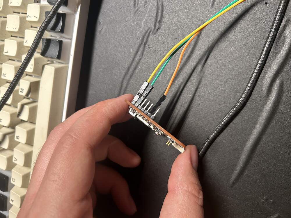
I do have a small problem - the Quentorres as I built it does not have pins attached to the prototyping holes on it. So I did a bit of quick soldering and added it in.
And then it was easy to set in all of the wires for the Servo
How to code a servo
The first thing when coding a servo is importing the proper library. In the case of programming with the Arduino IDE this reference works great:
SERVO REFERENCE
In short there are a few steps to follow:
- Add the Servo.h library
- define a Servo Pin (in my case 4)
- Set a name for the Servo object
- In void setup attach the servo
- In void loop decide where the servo will be moving.
- To do this you use [SERVONAME].write(ANGLE_YOU_PUT_SERVO_TO)
- This is limited from 0-180 for my servo and varies depending on the servo itself.
When you put it together the code looks like this:
Servo Code
        #include
          #define led_pin 26
          #define led_pin2 0
          #define button_pin 27
          #define led_pin3 1
          //Setting up the ServoPin
          #define ServoPin 4

          //naming the servo object
          Servo myServo;

          void setup() {
             pinMode(led_pin,OUTPUT);
             pinMode(led_pin2,OUTPUT);
             pinMode(led_pin3,OUTPUT);
             pinMode(button_pin,INPUT_PULLUP);
             Serial.begin();
             Serial.setTimeout(10);

             //attaching the servo pin
             myServo.attach(ServoPin);
             }

          bool button_up = true;

          void loop() {
            //myServo.write(90);
             if (Serial.available()) {
                digitalWrite(led_pin,HIGH);
                //adding code here to test my LEDs
                digitalWrite(led_pin2,HIGH);
                digitalWrite(led_pin3,HIGH);
                String s = Serial.readString();
                Serial.print("you typed: ");
                Serial.println(s);
                delay(100);
                digitalWrite(led_pin,LOW);
                digitalWrite(led_pin2,LOW);
                digitalWrite(led_pin3,LOW);
                }
             if ((digitalRead(button_pin) == LOW) && button_up) {

                //setting servo to 10 degrees when button is not pressed
                myServo.write(10);

                digitalWrite(led_pin,HIGH);
                digitalWrite(led_pin2,HIGH);
                digitalWrite(led_pin3,HIGH);
                Serial.println("button down");
                button_up = false;
                }
             else if ((digitalRead(button_pin) == HIGH) && !button_up) {

              //adding servo
              //setting servo to 170 degrees when button IS pressed
              myServo.write(170);

                digitalWrite(led_pin,LOW);
                digitalWrite(led_pin2,LOW);
                digitalWrite(led_pin3,LOW);
                Serial.println("button up");
                button_up = true;
                }
             }
The Servo Working
This is very cool, but DAP-R needs a bowtie so I threw together a quick design on Fusion 360 and added a bowtie to the Servo instead of the regular Servo Horn.
If you watch this video you may see that I added a little bit to the code and made the lights turn on and off in sequence. This was using two tools. The fact that the LEDs are controlled by LOW and HIGH functions and
- ALL LEDS ON
- LED1 ON LED2 ON LED3 OFF
- LED1 ON LED2 OFF LED3 OFF
- ALL LEDS OFF
When the button is pressed the system cycles through all of these states.
        #include
          #define led_pin 26
          #define led_pin2 0
          #define button_pin 27
          #define led_pin3 1
          #define ServoPin 4


          Servo myServo;

          void setup() {
             pinMode(led_pin,OUTPUT);
             pinMode(led_pin2,OUTPUT);
             pinMode(led_pin3,OUTPUT);
             pinMode(button_pin,INPUT_PULLUP);
             Serial.begin();
             Serial.setTimeout(10);
             myServo.attach(ServoPin);
             }

          bool button_up = true;

          void loop() {
            //myServo.write(90);
             if (Serial.available()) {
                digitalWrite(led_pin,HIGH);
                //adding code here to test my LEDs
                digitalWrite(led_pin2,HIGH);
                digitalWrite(led_pin3,HIGH);
                String s = Serial.readString();
                Serial.print("you typed: ");
                Serial.println(s);
                delay(100);
                digitalWrite(led_pin,LOW);
                digitalWrite(led_pin2,LOW);
                digitalWrite(led_pin3,LOW);
                }
             if ((digitalRead(button_pin) == LOW) && button_up) {
                //adding servo
                myServo.write(10);

                //This block shows the delay of starting with one LED lit and lighting up all three at the end.
                digitalWrite(led_pin,HIGH);
                digitalWrite(led_pin2,LOW);
                digitalWrite(led_pin3,LOW);
                delay(250);
                digitalWrite(led_pin,HIGH);
                digitalWrite(led_pin2,HIGH);
                digitalWrite(led_pin3,LOW);
                delay(250);
                digitalWrite(led_pin,HIGH);
                digitalWrite(led_pin2,HIGH);
                digitalWrite(led_pin3,HIGH);
                delay(250);


                Serial.println("button down");
                button_up = false;
                }
             else if ((digitalRead(button_pin) == HIGH) && !button_up) {
              //adding servo
              myServo.write(170);

                //This block shows the LEDs turning off one by one.
                digitalWrite(led_pin,HIGH);
                digitalWrite(led_pin2,HIGH);
                digitalWrite(led_pin3,LOW);
                delay(250);
                digitalWrite(led_pin,HIGH);
                digitalWrite(led_pin2,LOW);
                digitalWrite(led_pin3,LOW);
                delay(250);
                digitalWrite(led_pin,LOW);
                digitalWrite(led_pin2,LOW);
                digitalWrite(led_pin3,LOW);
                delay(250);
                //end of block

                Serial.println("button up");
                button_up = true;
                }
             }
What did I learn this week? - How to use the pinouts on a SEEED XIAO
- How to light up LEDs attached to this using the Arduino IDE
- How to control a servo with the QuenTorres
- What do I want to learn?
- How to run the NeoPixel onboard the SEEED XIAO