Group Assignment
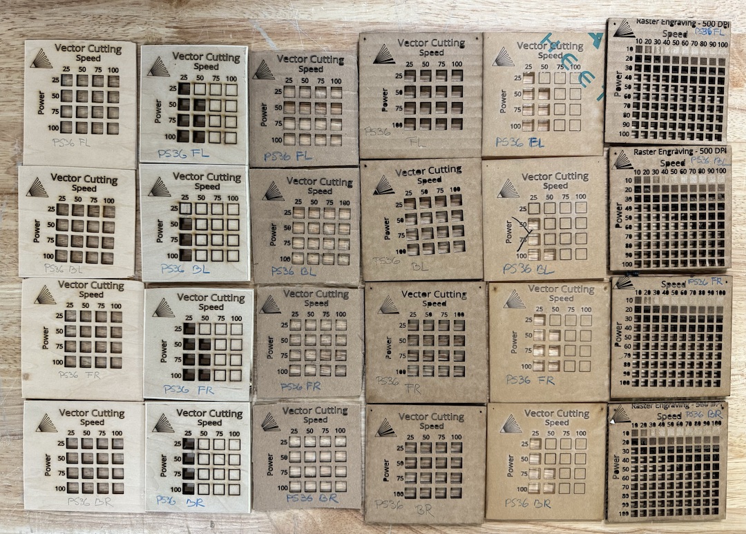
We tested the vector cutting in a grid array that varied the Power intensity from 25 to 100 in 25 percent increments in the Y axis, and the speed from 25 to 100 in 25% increments in the X axis. We ran these tests on 1/8" basswood, 1/4" plywood, 1/16" corrugated cardboard, 1/4" corrugated cardboard, and 1/4" acrylic. We then ran a raster engraving test with the same power and speed variability on the Y and X axis, but increased it to show it in increments of 10% so we had a more preceise array of intensities.
I learned that a lot of different materials have similar properties when it comes to cutting through them in power and speed. But a big factor in this is the actual thickness. Higher power also causes more scorching so dialing that in is very very important when it comes to a clean outline.
Cutting something on the vinyl cutter
Last week I redesigned something on Illustrator, my little buddy/logo for my company Perez Robotics LLC. Unfortunately, unlike DAP-R little buddy doesn't really have a name so we will just stick to Buddy for now. If you haven'y had a chance to look at Week 2. Here is a little reminder at what we are looking at:
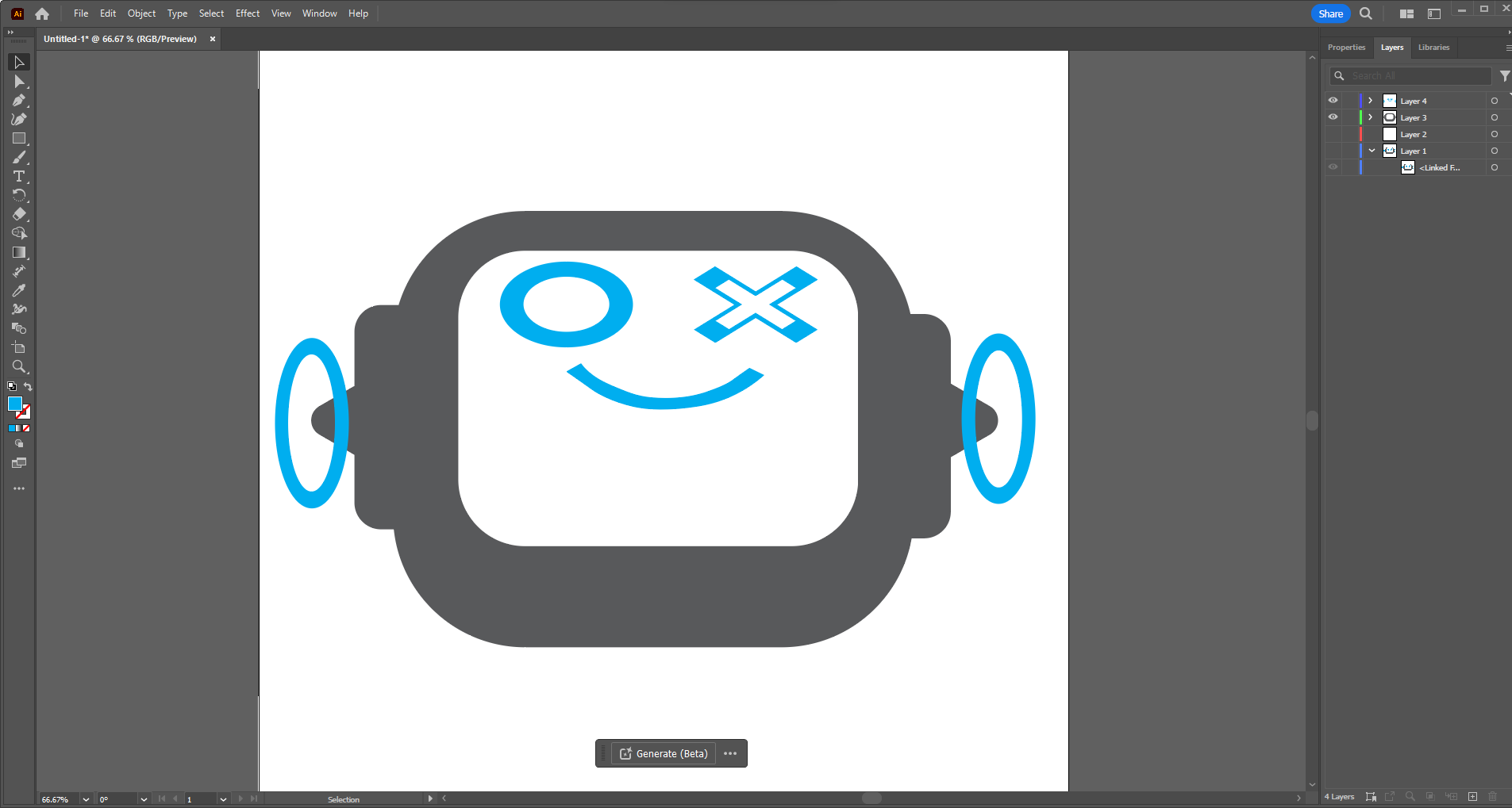
If you'd like you can click above and see the process of creating him again!
But, I digress, making something like this is no use unless you can make a little bit of swag of it. So I did what any self respecting maker would do and made a vinyl decal of little buddy. At my home lab, the Roberto C. Goizueta Innovation Center, we have a Cricut Maker on site. Two of them actually. So my choice came down to using this as my CNC controlled cutter for vinyl. I know I can use a laser but we will be going over that process later with the press fit device.
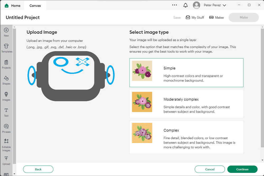
Cricut is interesting in that it has a proprietary software for the processing of files. This is called Cricut Make. It is pretty simple. Drag and drop with some minor processing for something like we are doing today. However as you will see I ran into some snags.
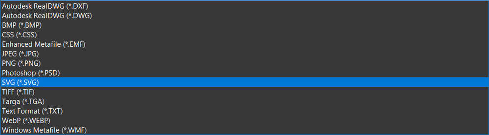
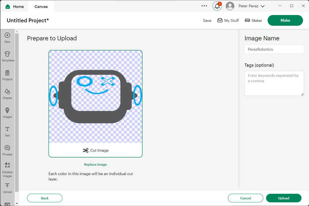
Uploading files is easy and it accepts most image file types. But the true strength of the program comes in when you use .svg file times. This allows the image colors to be differentiated into different cuts. Especially after being designed from scratch on Illustrator or a similar program.
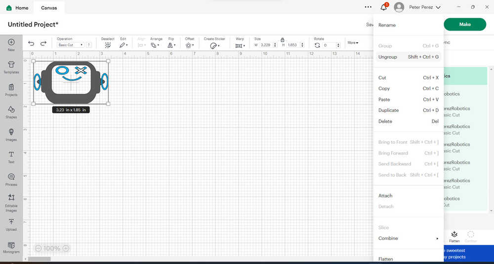
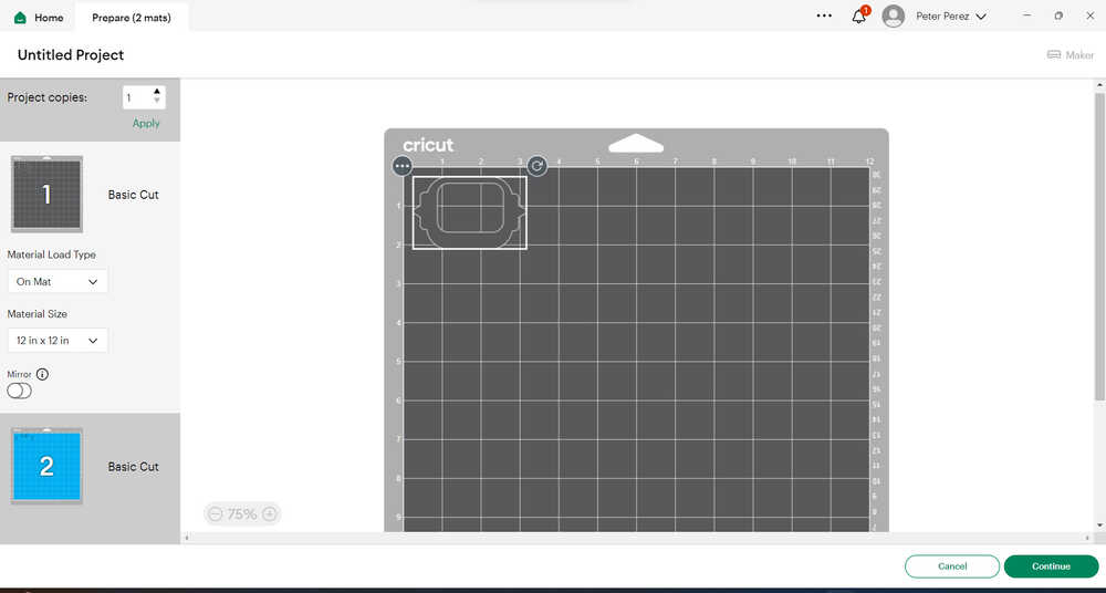
Once brought in the image needs to be resized to something realistic that you would like to use for your final sticking place. Here I brought it down to something like 3 inches wide in the end so it would be a reasonable sticker size. If you look to the right of the screen you see the power of the svg. All of the different shapes that are in the design are brought in separately. That way you can cut and customize the design however you like. It is necessary (and makes your life a lot easier) when you group the images together so that they stay in their final orientation. If you do not do that they all arrange to best fit and then you have to move them yourself. This is no fun at all.
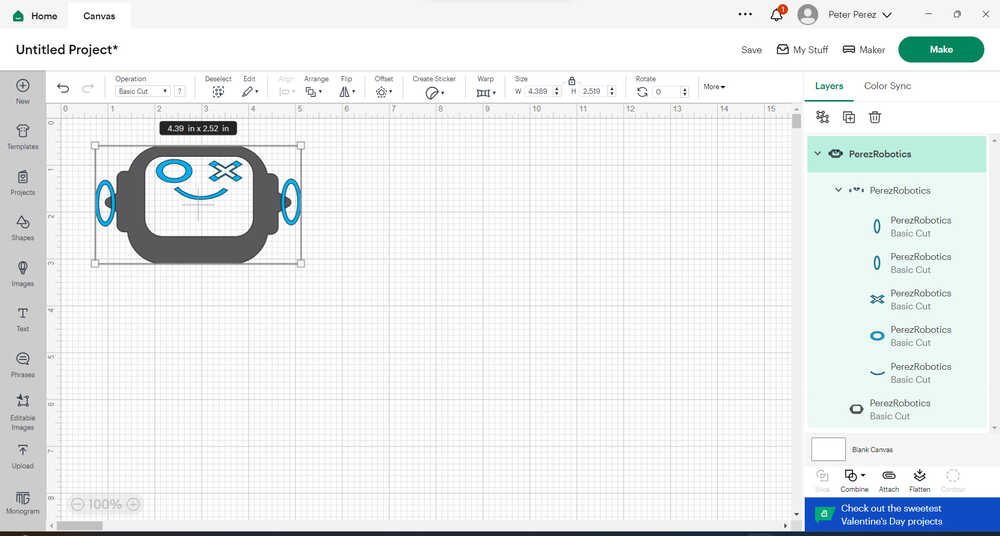
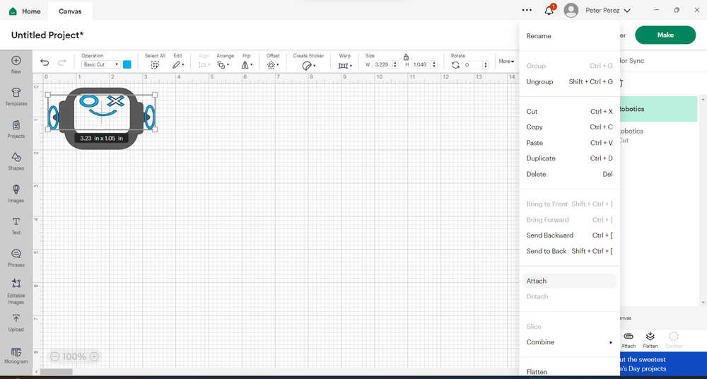
I had to first ungroup all of the PerezRobotics images that were stacked together so that the grey and the blue are not one unit and then I had to attach together all of the blue detail shapes on the cutter.
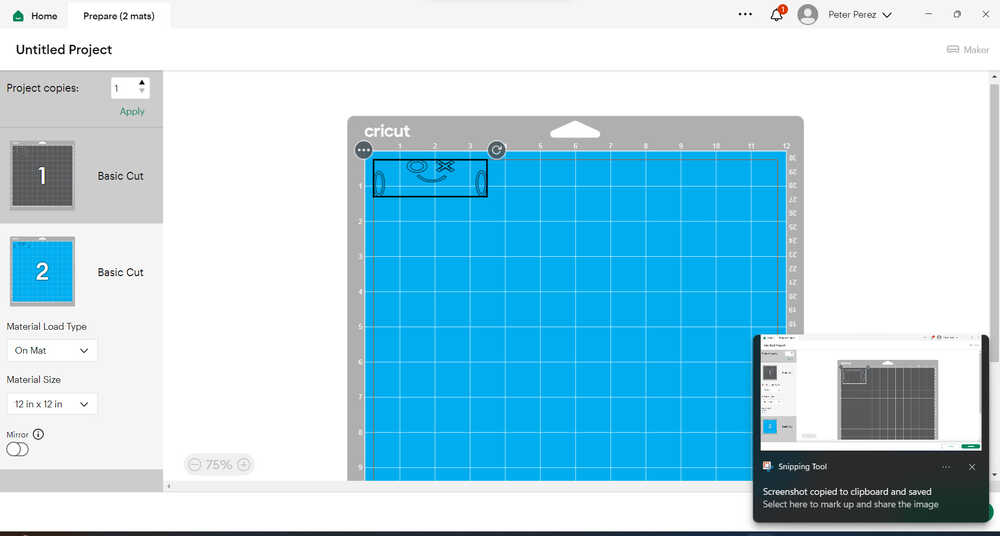
Once you do that and export you can see that the two different colors break up into two different mats to cut. Aka, two different color vinyls. You can get creative and splice together vinyl sheets and do a lot more but I do not recommend it. I have tried. It's the biggest headache.
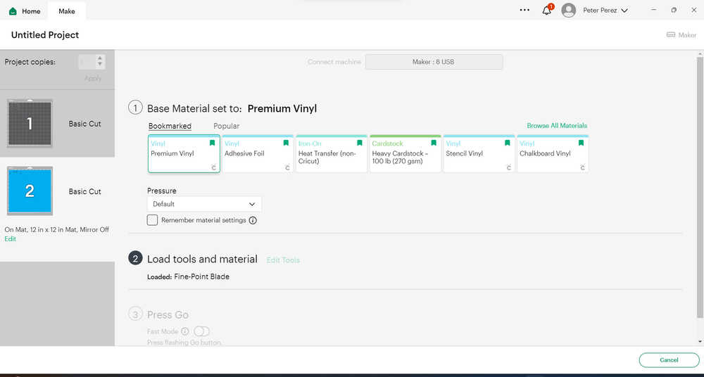
After this you pick which vinyl you want to use and I knew in the lab we had the proprietary Cricut "Premium Vinyl"
Off to the Real World
Now that I have set up the file and what I wanted it to do it is time to put together the actual cuts and see what colors we have. When I went to look it looked like I didnt have the blue and grey/silver that I originally designed it in. Looks like I am going to have to go Black and Red and do an "Evil Little Buddy"
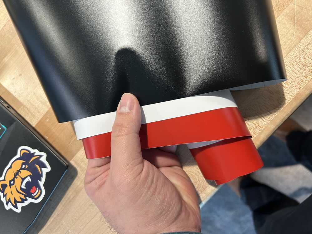
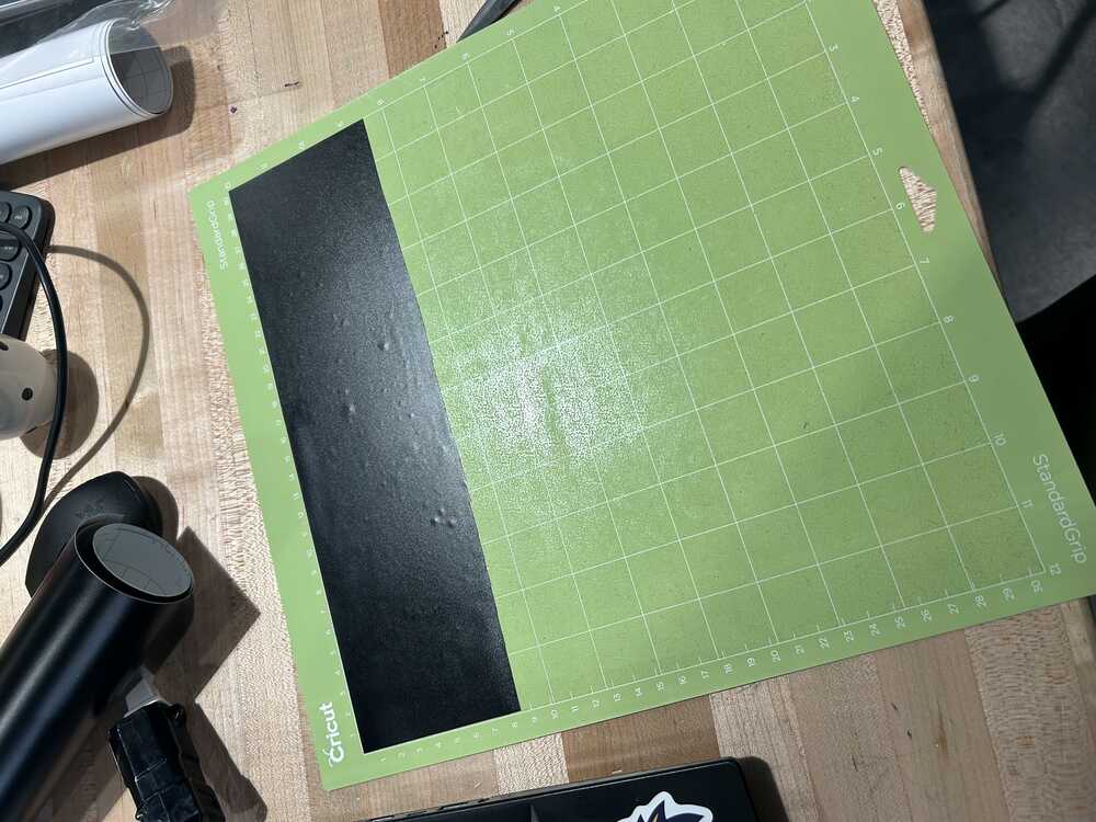
After this you lay the vinyl on the mat and set it into the machine. Make sure that where you put the vinyl lines up with where the design is on the sample mat. Then follow the on screen instructions to let it cut.
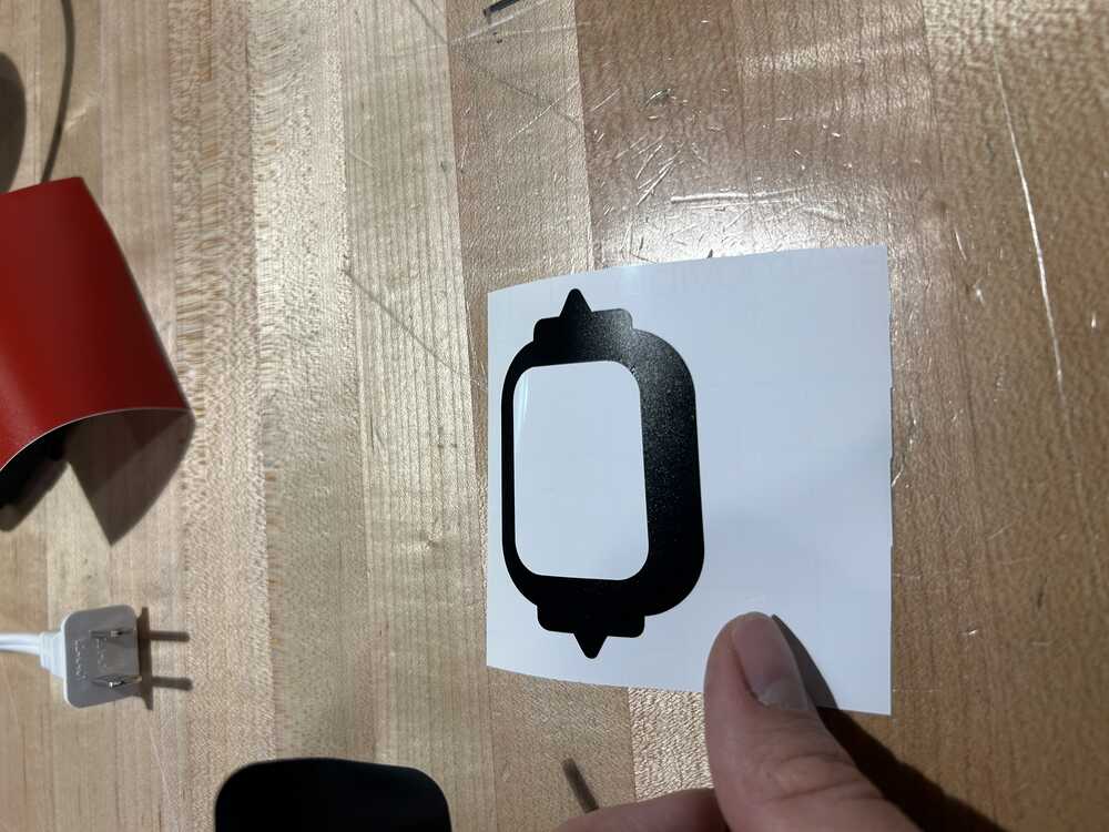
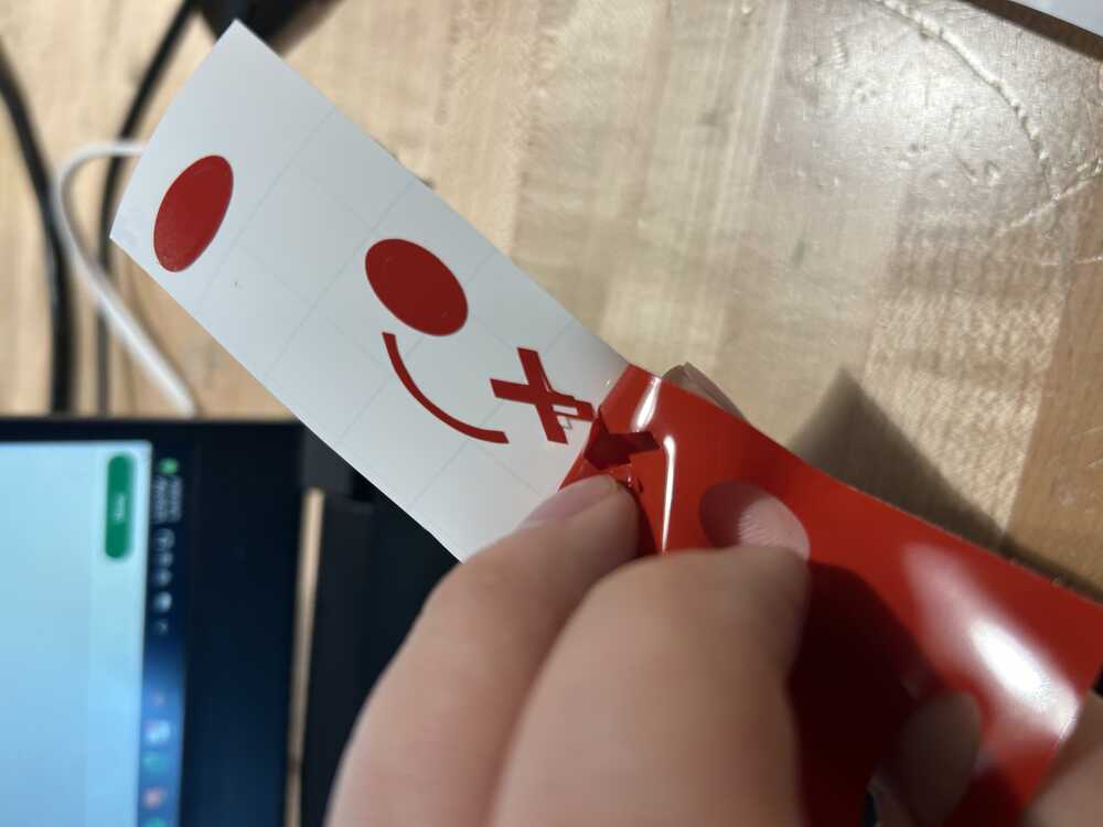
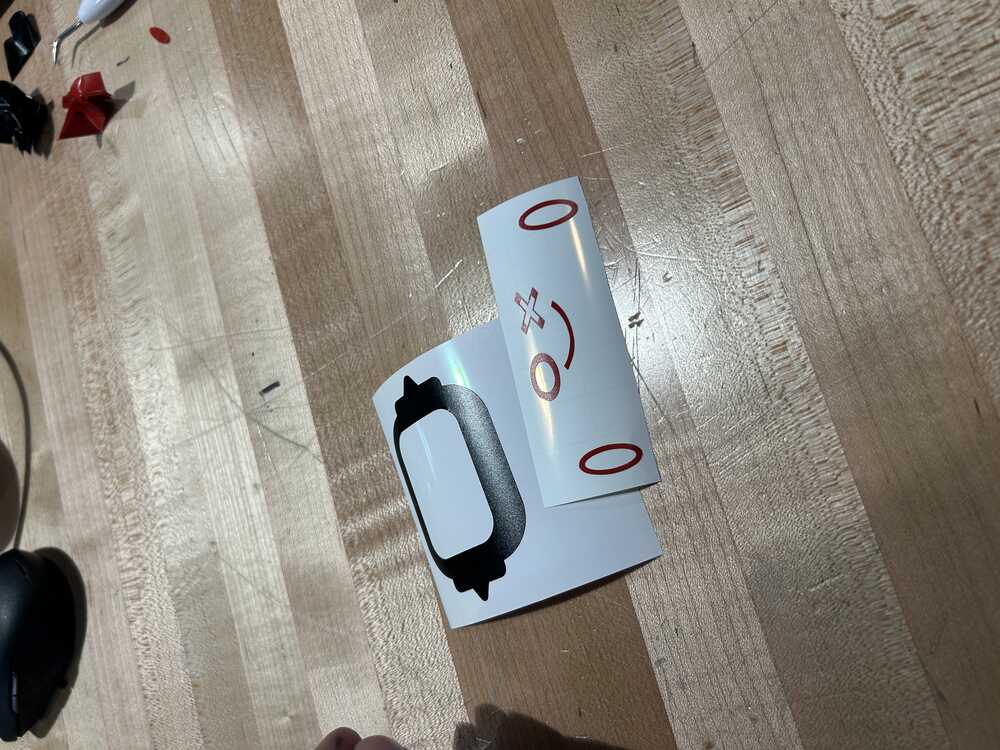
Once this is done you have to start with the weeding process. As you can see in the video the entire vinyl is still on the page and the excess needs to be removed. I find this the most annoying part of the process because a small mistake can make it so that your design does not come off easily. I actually almost messed up and you can see that in the second image below where the little "X" eye almost came apart!
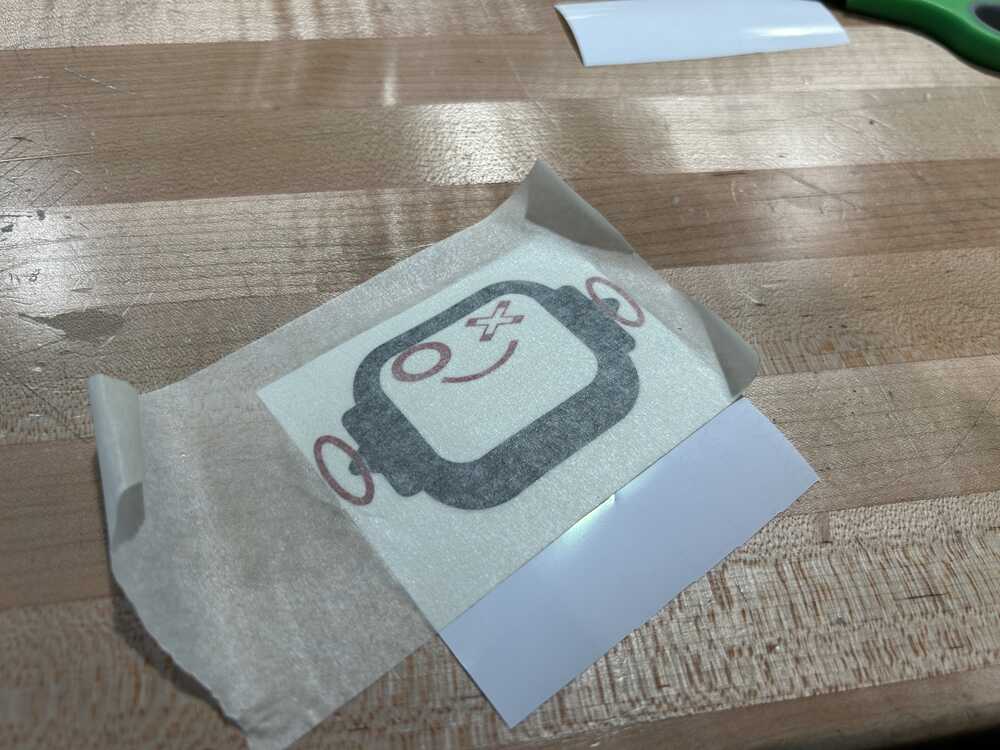
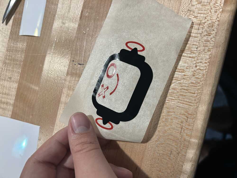
When you are done weeding you will have one sheet of each color vinyl left behind with only what you want. Here, you are supposed to used transfer paper to move the image from its current paper to another. I don't do that. I prefer something simpler: masking tape. I do not know why but this always works better for me and has given me good results since I started working with it. The trick is lining up your images properly. Only trick I know is to line it up, hold my breath, and commit.
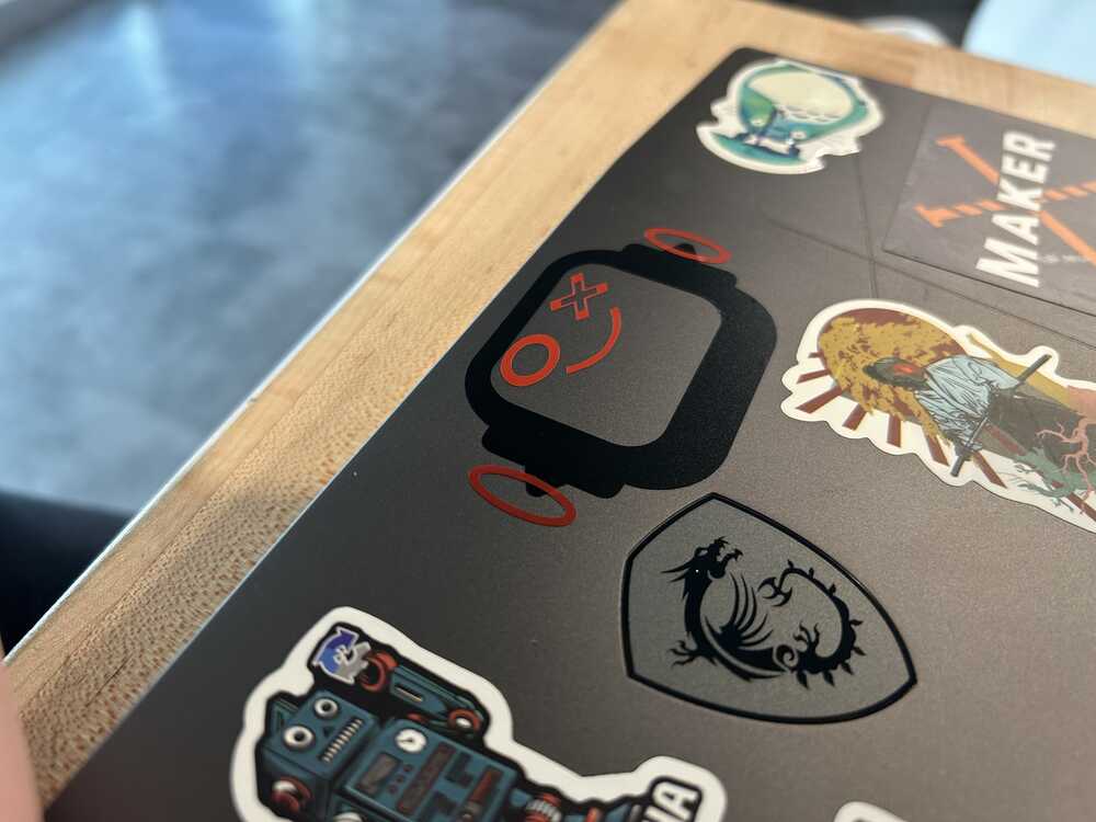
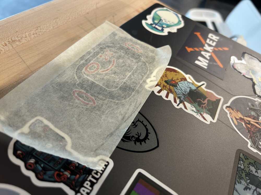
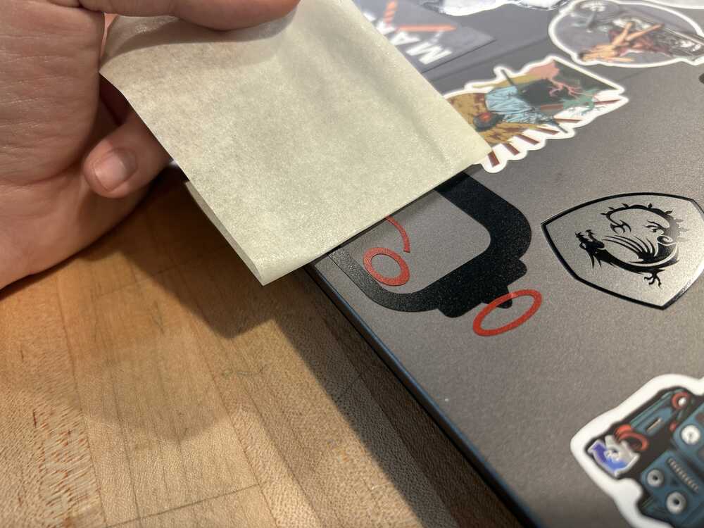
Finally, we can add it to the infinite sticker collection
The final step, and most fun is to put your attached images on their final resting place. I chose, as many do, my laptop. Now little buddy can go with me everywhere (I will probably make a few more after this now too). Once you have the masking tape ready, you can go ahead and place it in the final location. Rubbing the vinyl vigorously is what I do to have it stick well and then I gently peel off the masking tape. If all goes well it will stick to the place you want with good strength.
The Final Product
Short Vinyl Debrief
Below is the svg that I uploaded onto the Cricut Maker app
Perez Robotics svg
The Cricut and Cricut maker app are lenient on settings and great for beginners. As shown above you can choose the material you have and the program will set pressures and more automatically.
I got curious and looked into what the settings would be for the Cricut Premium Vinyl in this device. For the maker they are completely hidden but if you look at this site it looks like the settings in general are a "3" on depth. Which is a medium range for the 1-5 range of this machine and "Medium" pressure. So it seems like its the most standard of materials. I am not sure what makes it premium but it is a selling point I am guessing.
THE PRESS FIT PUZZLE ODYSSEY
I will begin by saying the odyssey of this design is fraught with misreading instructions and headaches on headaches of design.
The long and short of it is, I designed something, it worked, I checked the requirements, I did it wrong, I had to redesign it. But the skills I learned along the way made it much better. Frankly, it made it easier too.
To begin this process I thought I just had to create a press-fit model. So to simplify my work I started designing a press fit lamp because that is what I wanted to do with my students at the school I work at daily.
In Fusion360 parametric design is done through constraints and parameters. These can be defined in two ways. First by adding them in prior using the User Parameters tool.
.jpg)
Or by defining them directly when you define a parameter in your sketches.
Here I was defining LampHeight directly with the sketch.
.jpg)
I sketched out the general idea for my lamp, a set of rings at parametrically defined distances that could stack on top of each other. These would have supporting beams to hold them together.
Playing with the parameters allowed me to change the ring widths. And then create more interesting shapes in the design. In the end I only chose 2 ring widths but with the design here you can see all 3.
The next step was to to create the slots for the legs to slot into
.jpg)
The best part about this is that using the parameters I can change the number of legs that I will be working with easily.
The legs were designed to be able to resize themselves (with a few limitations) when the rings were resized as well as the thickness of the material. Keeping things truly parametric.
Transitioning to Illustrator to cut
After this I transitioned the images to illustrator to be able to send them to the laser cutter. The procedure to do so is pretty simple
- Exporting to Illustrator from Fusion:
- Export your sketches as a .svg file
- Open Illustrator
- Create an Artboard the size of your laser bed
- Click File > Place
- The image should appear on your screen and you can move it to where you want to.
In the end it will look like the images below:
.jpg)
With the laser at the Moonlighter it is easy to connect to the cutter. All you have to do is be on the Wifi and type the local IP address of the tool onto your browser. It will open up an interface.
In this interface it is simple, you shift your image to wherever it needs to be on the screen and you can use the program to shift each of the parts to a place where they fit.
It is good form to circle perimeter after this to be able to see where the laser is going to cut and if it makes sense with what you are building.
On the bottom right you can set your power and speed (as found when you characterized your laser) and then click Run
Then you sit and wait.
After this, I had an issue.
Upon printing and trying to put the thing together, I did not actually design them well or account for the kerf and I had the wobbliest lamp that man ever did see.
So I went back and created a Kerf tester.
- Kerf Tester
- Create an array of holes.
- Speaking to Daisy, she suggested to try 2% increments
- So using the parameter I defined as the material thickness I multiplied this by increments of +/- .02
- Then I cut and tested with the material
Turned out a size of 92% of the theoretical size worked best.
Then I recut the whole assembly slotting that in as my material thickness and tried to get it to slide in. It did, very well!
.JPG)
Now, we all see the problem
I looked at the requirements, and noticed it had to be done in multiple parts... and something multi-configurable. And that lamp, is definitely not.
So instead I decided to use a little geometry and parameters and designed a polygon generator.
We all know that polygons can be created from a set of triangles that go through the center. All that differentiates them is their interior angle and height.
Something that looks like this:
.jpg)
This worked out perfectly, but I forgot about changing the height of the triangle, so I ended up originally with something like this when I tried to pattern beyond 4 instances.
.jpg)
So I had to go back and do the math mentioned above:
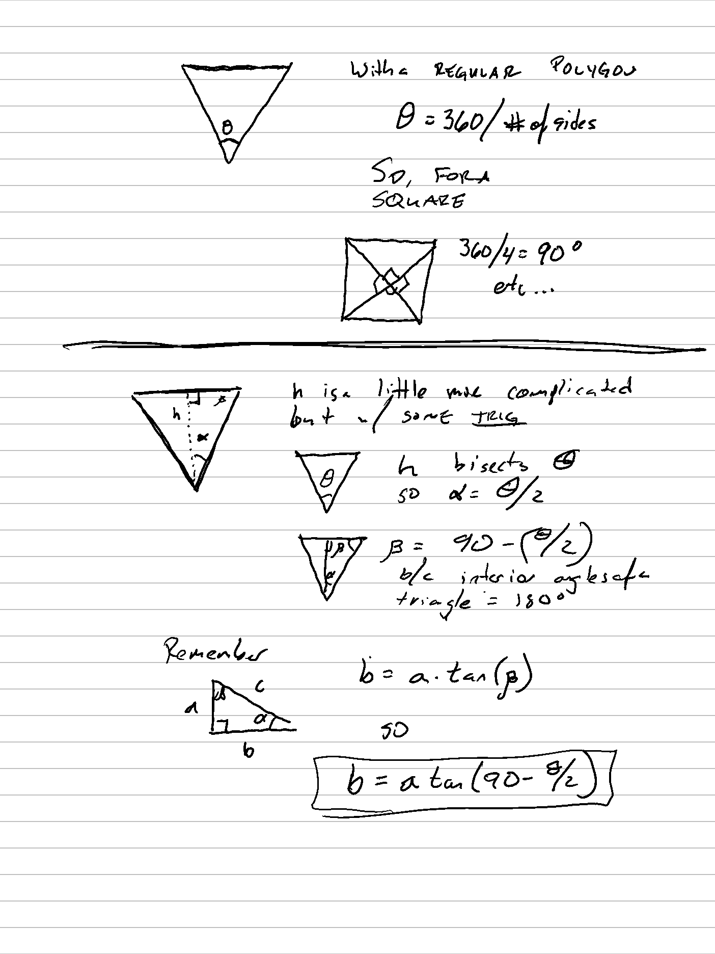
.jpg)

With this I got a system that WORKED.
And most polygons would generate well!
.jpg)
Cutting again.
I followed the same procedure as above and this time instead I did it on my work glow forge.
I also learned from before and created my sizing tool immediately and then cut out my kit. I think it came out pretty well!
A few things on the laser cutter
For this test I used two materials for testing and for the final product. The testing for this material was done on 1/8" basswood
On the laser cutter the settings for cutting were a Power of 100% and a speed of 500 out of 1000 on the program.
If you want more sides you can dl the Fusion file and change the parameters
What I Learned This Time
Vinyl cutting is fun, but you have to pay close attention to your design
On a cricut remember about group and arrange
Group just puts different shapes together.
Arrange groups together images in their orientation, making it MUCH easier to arrange your designs later
Masking tape works just as well as transfer tape for moving vinyl
KERF IS SO IMPORTANT FOR PRESS FIT
Parametric design on Fusion is not perfect. Regeneration after changes can have a lot of problems
Remember your basic geometry when designing these constraints too.
These puzzles are really fun to make and I kind of want to generate a huge set of them!
Ohad, our mentor, taught me about cleaning the collimator on my Glowforge and how it will fix my scorching. I am on my way to doing this now. You can just use degreaser but Oxyclean or detergent works too!


.jpg)
.jpg)
.jpg)
.jpg)
.jpg)
.jpg)
.jpg)
.jpg)
.jpg)
.jpg)
.JPG)
.JPG)
.JPG)
.JPG)
.JPG)
.JPG)
.JPG)
.JPG)
.jpg)
.jpg)
.JPG)
.JPG)
.JPG)
.JPG)