Introduction
This week’s objective was to make a machine. I chose to make a custom cable robot using inexpensive components. Due to the current context of our lab, I had to work alone, as I am the only student, and our lab is still in its early stages (year zero). Given the limitations, I opted for a cable robot, which is simpler to build compared to other machines.
Throughout the week, I collaborated remotely with our instructor, Ohad. We reviewed the project through video calls, where Ohad provided feedback on the design and the firmware setup. Although I couldn’t collaborate with a colleague in the lab, I worked closely with Ohad to troubleshoot and refine the process. I structured the week to ensure steady progress: first focusing on the firmware and electronics, followed by the mechanical assembly and testing phases.
Here’s a breakdown of my process:
- Identify a firmware that supports polar coordinates (necessary for cable-style machines like a polargraph).
- Customize the firmware to fit the motors and gears I am using.
- Test the motors to ensure proper movement.
- Design and 3D print the components to mount the robot.
- Test the setup with Pronterface to control the robot.
- Send basic G-code commands for straight-line movements and test that everything works as expected.
Not completed yet:
- Custom UI for generating G-code (UI week).
The concept of a cable robot is to “hang” the body from two cables, which are tightened or loosened by two motors, providing two-dimensional movement.
Objectives
- Build a cable XY plotter.
- Use GRBL or a similar firmware.
- For now, the objective is to draw a square.
- 3D printed parts.
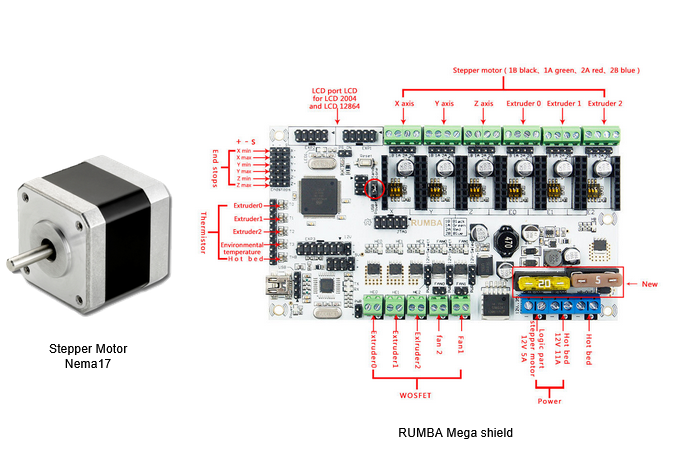
- Rumba control board.
- Steel ball chain.
- 2 x 608 bearings.
- M3 bolts, spacers, and nuts (various sizes).
- Computer power supply (12v).
- Open builds beam to mount brackets.
- Drop-in nuts for the beam.
- 2 NEMA 17 stepper motors with cables.
- Pronterface for initial communication and movement.
Total cost: less than $100.
Process
I started by using a previous project as a reference. I modified the gears to fit the metal ball chains and redesigned the motor brackets for a cleaner, more concealed design. I initially got it working with an old Rumba board (circa 2014) from a 3D printer I built years ago. I reconfigured the Repetier firmware (which has a cable robot setting) to match the stepping distances, adjust for the board, and strip down unnecessary settings.
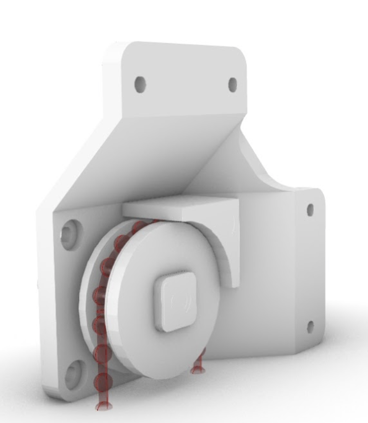
Next, I printed the parts:
I then assembled the machine:
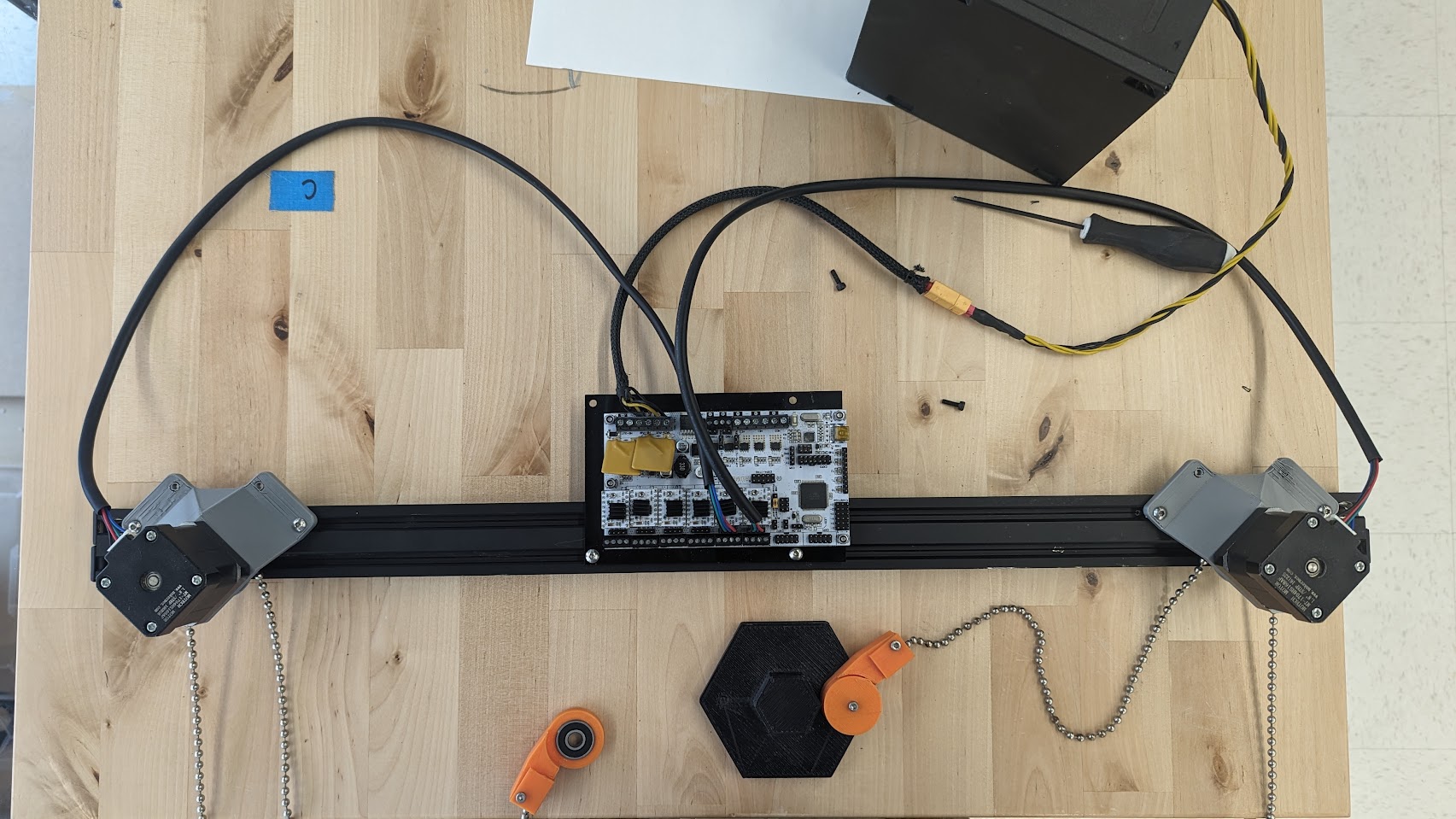
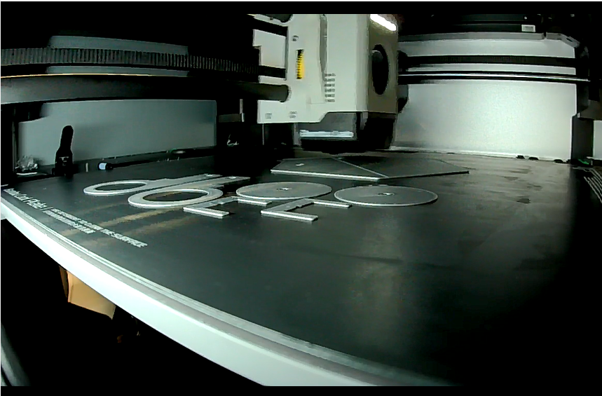
After assembling, I connected all the components and began testing the setup using Pronterface for initial control:
Now it’s time for calibration:
Once I had the correct values, I used the following G-code to configure the machine:
1
2
3
4
5
6
| M4 X E S P
X is machine width
E is pen Width
S is steps per rev
P is mm per Rev
|
….
Where:
X is the machine width.E is the pen width.S is the steps per revolution.P is the millimeters per revolution.
Working Plan and Week Structure
I structured my week to balance remote collaboration and hands-on work effectively. Here’s a rough breakdown of how I managed my time:
- Day 1-2: Firmware research and configuration. I reviewed different firmware options with Ohad and selected Repetier because of its cable robot compatibility. I spent these days setting up the Rumba board and testing motor configurations.
- Day 3-4: Design and 3D printing. I worked on modifying and printing the motor mounts and pulleys.
- Day 5-6: Assembly and initial testing. I assembled the machine, connected it to Pronterface, and began preliminary movement tests.
- Day 7: Calibration and refinement. I worked on fine-tuning the machine’s calibration and setting the proper G-code parameters.
Although I worked alone physically in the lab, I maintained close contact with Ohad throughout the week for troubleshooting and guidance.
Conclusion
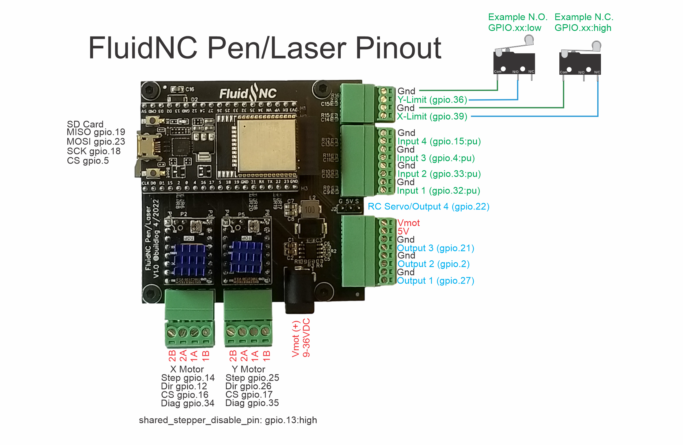
Cable robots are an excellent solution for large-format processes with a low cost. For future improvements, I could extend the design to a three-dimensional cable robot and potentially use an ESP3D-based controller to reduce the need for cables. There is also an interesting module called FluidNC, which is GRBL-compatible and could offer better flexibility.
Files