Introduction
This week’s goal was to produce a PCB using a mill, a laser, or another method capable of selectively removing or adding material between conductive and insulative layers to create a circuit board.
Objectives
- Mill and produce the Quentorres board.
- (Optional) Use Blender to generate the G-code for the board production.
- Bantam Tools Desktop CNC Mill (older model)
- Mods for toolpath generation
- 1/32 flat end mill bit (for holes and outline)
- 1/64 flat end mill bit (for traces)
- Blender for alternative G-code generation
Process
-
Initial Milling: I started by milling the Quentorres board. For my project, I’m considering using I2C to integrate components like OLED displays, knobs, and sensors. The QTPY has a compatible layout with the XIAO, offering a potential solution.
-
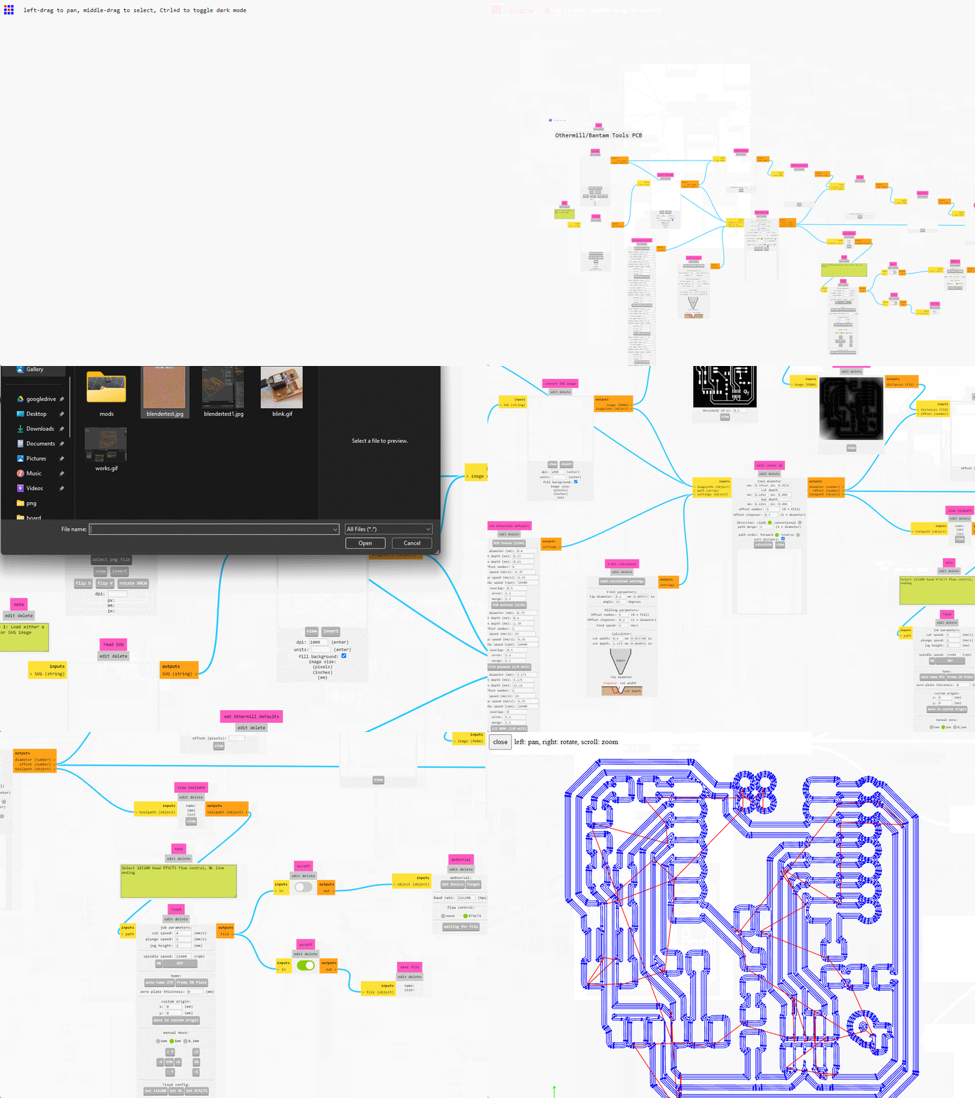
Toolpath Generation with Mods: I downloaded the design files from the Quentorres repository and used Mods to simplify the development of toolpaths. Mods provide presets for the Bantam Tools CNC, making it easier to set up the milling process for each layer.
-
Exporting G-code: After setting up the design in Mods and calculating the toolpaths, I exported them as TinyG code. Bantam Tools’ software was then used to load these files for milling.
-
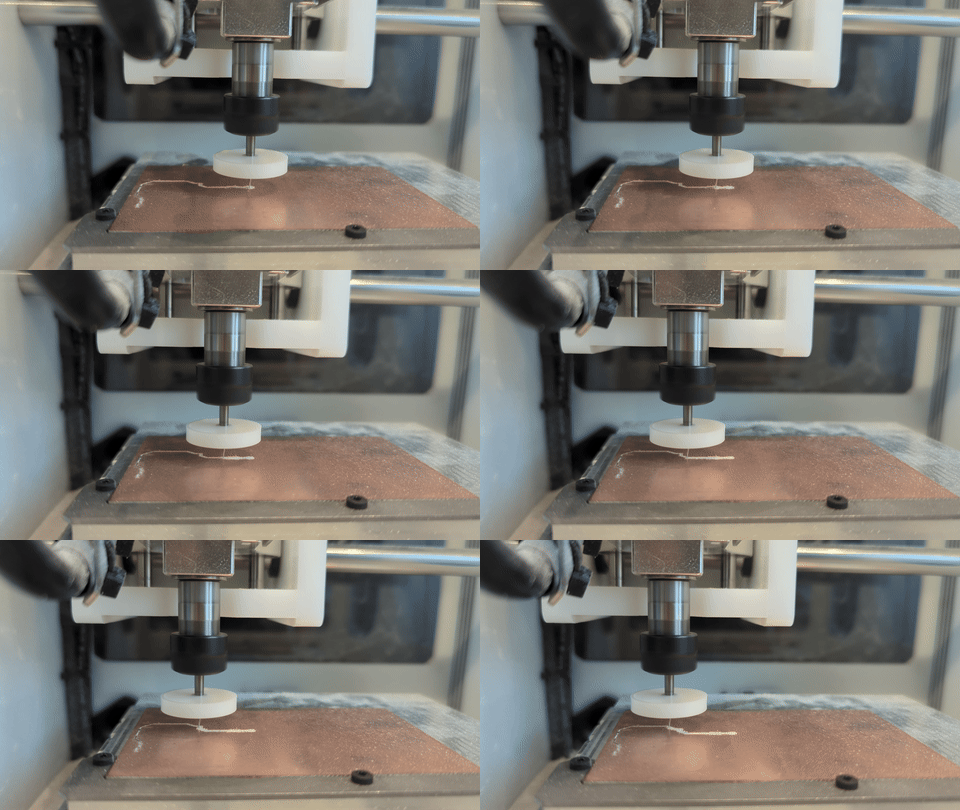
Milling and Assembly: The Bantam Tools software guided the setup:
1.- Home the machine using the Home button this will locate the tool
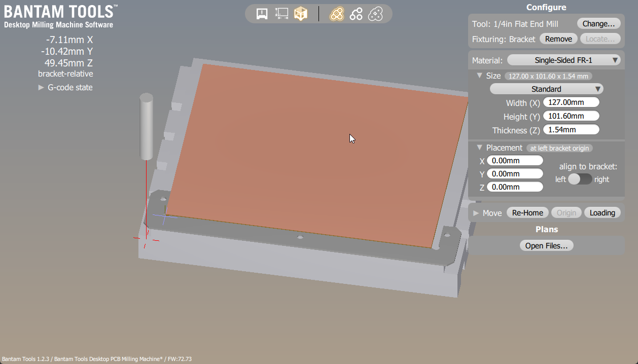
 2.- install the PCB bracket and follow the calibration tutorial, to ensure the PCB can align when your flip your board in case you want to mill both sides, also here you can input the size of your pcb and its alignment relative to the bracket. use double sided tape to keep the PCB in place when milling:
3.-Now setup to the tool so the z offset can be calibrated and you avoid any crashes,
First select the correct bit and install the new mill bit about 10 mm inside the collet,
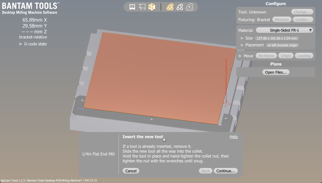 Now after securing the bit make sure that you send it to prbe top of the bed not the PCB!
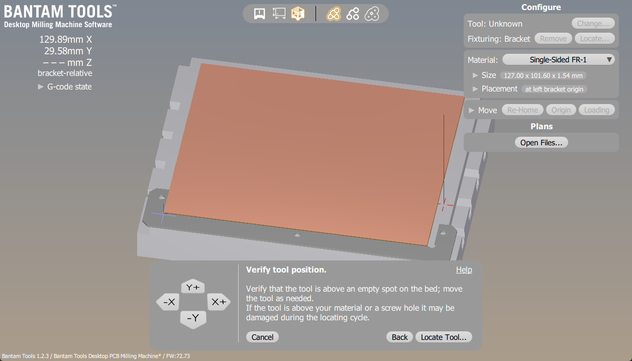 when running it something looks off , press the red button and check again, you might break the bit if you send it on top of something that is NOT electrically connected to the signal on the bed.
4.- Milling, I first milled the traces with the 1/64 bit, then switched to the 1/32 bit for holes and the outline, adjusting the Z-offset of the bit as needed. The milling process was smooth, thanks to prior experience.
-
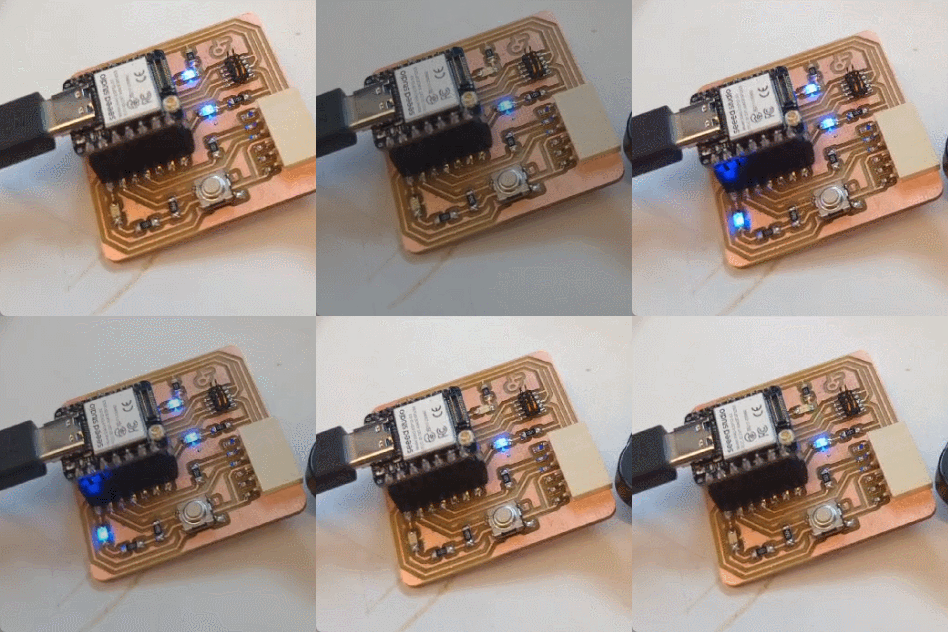
Soldering: I used solder paste for easier soldering of surface-mount components, utilizing a heat gun. To save costs, I opted for bent female headers to mount the board as they were cheaper.Soldering was straight forward and it was really nice to taste solder paste It is way easier than using the normal method.
-
Functional Test: A quick blink example confirmed the PCB’s functionality.
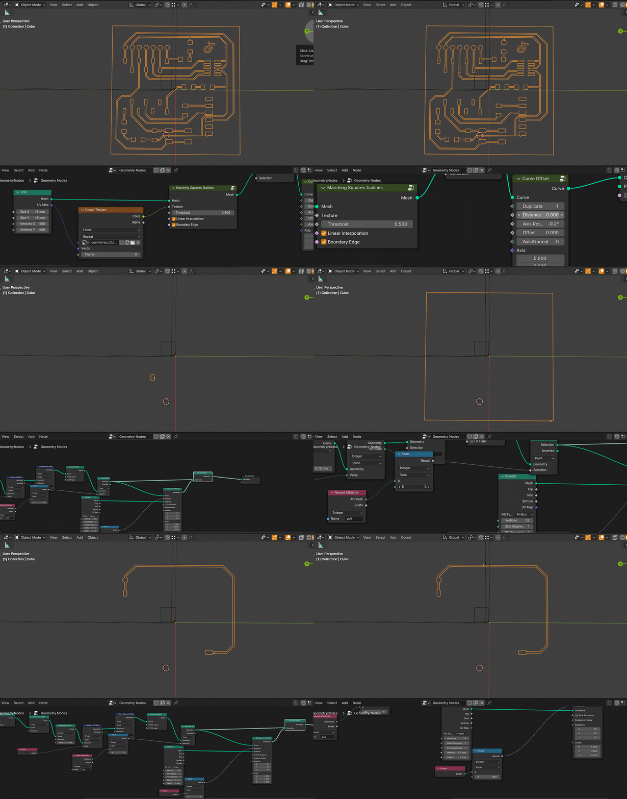
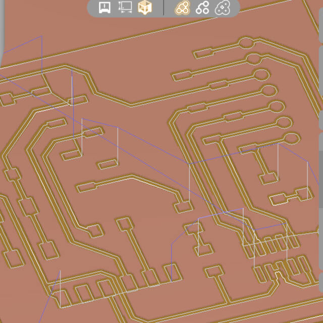
- Experimenting with Blender: Inspired by a tutorial on marching squares, I attempted to replicate the workflow in Blender for tracing PCB traces from an image. The initial tests did not yield perfect results due to insufficient offset in the traces, and I ran out of time.
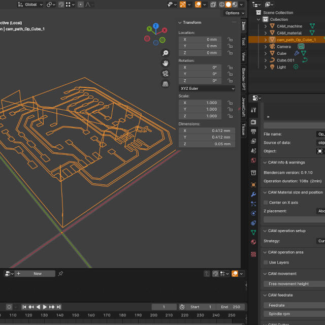
Using the generated curves I used BlenderCam to generate the Gcode this time (it was a bit faster to setup and I wanted to test the workflow)
Conclusion
The exploration of using Blender for the majority of the PCB production workflow revealed potential, despite some challenges with BlenderCAM’s setup. Further testing is required to streamline the process, I can probably adjust the geometry nodes script to avoid blendercam completely.
Files