Computer Aided Design
This week, my exploration in parametric design focused on creating a conceptual model for the NeoStruder Control Box using Geometry Nodes in Blender. Blender’s integration with Geometry Nodes enables a highly adaptable and powerful approach, making it ideal for complex designs.
Blender is available for download here.
Objectives
The primary goal is to craft a conceptual 3D model of the final project using CAD tools. I chose Blender and its Geometry Nodes for their robust parametric capabilities, which are crucial for detailed and flexible modeling.
Process
Step 1: Setting Up Geometry Nodes
Select the default cube and get a geometry nodes viewport, then add a new node tree to the cube:
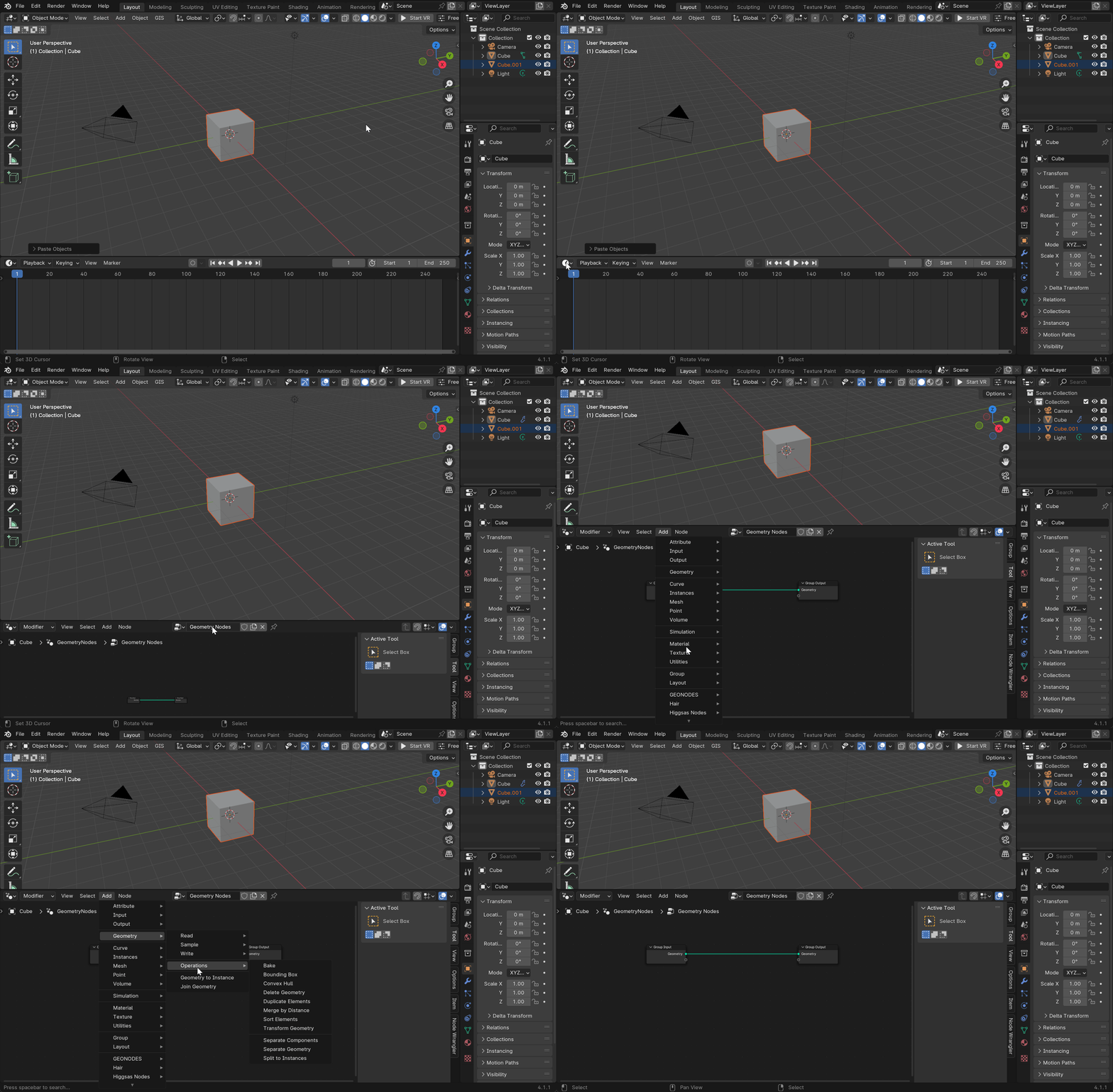
Here’s a glimpse into the geometry nodes setup, ill explain each node after the image:
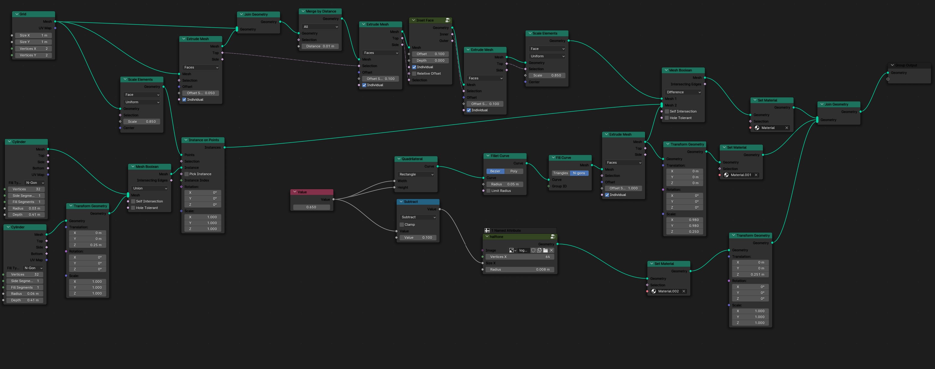
Overview of the Node Setup
The network is segmented into various components, each handling different aspects of geometric manipulation and design. Let’s examine each part:
Initial Geometry Creation
-
Grid and Cylinder Nodes: The setup begins with the creation of basic geometric forms, specifically a grid and two cylinders, which serve as the primary shapes for subsequent modifications.
-
Transform Geometry Nodes: These nodes adjust the position, rotation, and scale of the initial shapes, setting the stage for more complex operations.
Modification and Detailing
-
Scale Elements and Extrude Mesh Nodes: Following the initial setup, these nodes are employed to scale and extrude the meshes. This step is crucial for adding depth and complexity to the basic shapes.
-
Mesh Boolean Nodes: Utilized for combining or subtracting the geometrical forms, the Boolean nodes use the cylinders to alter the grid or each other, depending on the operation selected (union, difference, or intersection).
Distribution and Adjustment
-
Instance on Points Nodes: This part of the network involves placing instances of geometries on predefined points, likely on the vertices of the grid or another object, allowing for systematic distribution of shapes.
-
Quad Interpolation and Subtract Nodes: These nodes manipulate values that influence other operations within the setup, such as scaling or placement of instances.
Curve Handling
- Fillet Curve and Fit Curve Nodes: Help adjusting curve data, these nodes refine curves that define the boundary or affect the generation of shapes within the setup.
Final Composition
- Set Material and Join Geometry Nodes: At the end of the process, materials are assigned to the geometries, and multiple shapes are combined into a single cohesive output. This step marks the culmination of the geometric creation process.
Step 2: Material Setup
Materials were assigned as follows:
- Glass: Used for the front of the box to allow visibility inside.
- Light Emitting Material: Enhances the “pixels” to emit light.
- 3D Printed Material: Mimics the appearance of 3D printed textures.
- Metallic Material: Applied to the bolts for realism.
Step 3: Lighting and Rendering
Implemented three-point lighting to enhance the visual dynamics of the model, and then proceeded to render the scene by clicking the render button.
Final Render
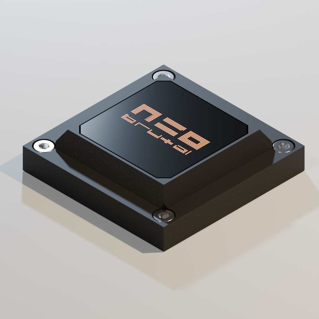
Here are the final renderings of the NeoStruder Control Box, showcasing the detailed modeling and material effects:

Additional View:
Conclusion
This Geometry Nodes setup in Blender exemplifies the capabilities for creating editable and repeatable models where changes to node inputs can parametrically alter the final output. Such setups are very helful for non-destructive editing and offer extensive possibilities for experimentation and design in 3D modeling.
2D
We can export a 2D SVG file for fabrication purposes.
For this I activated the Free Style SVG exporter in the Preferences, this addon exports the edges of a mesh as an SVG file fomat.
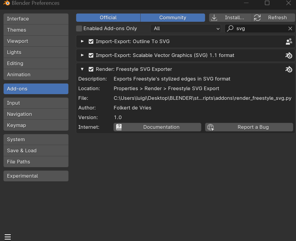
then you activate the Freestyle checkbox and freestyle svg export checkboxes on the properties panel:
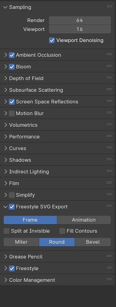
After rendering (with F12) the scene, Blender will save an 2d SVG file of your 3D model.

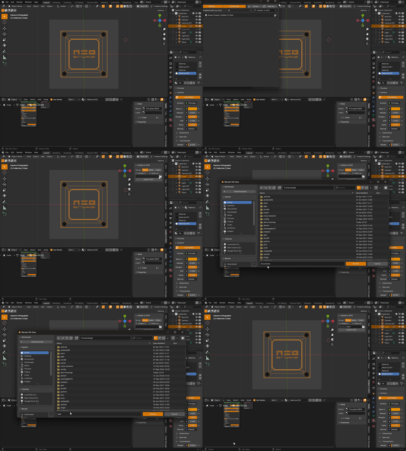
Also by using the export outline addon its possible to get precise shapes,
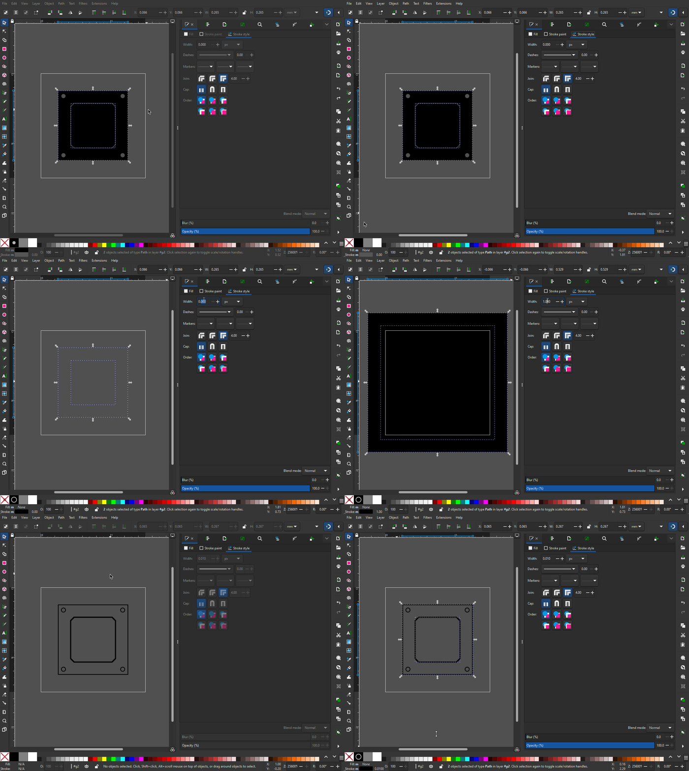
we can open this on any 2D vector sofware or CAM to process the file for plotting, cutting or even milling.
Conclusion
Blender can be used for generating not just 3D files for 3D printing but also 2D files for fabrication.
Blender can be used to generate the 3D files required for fabrication, then its possible to export .svg files that can be used for cutting with a laser, cnc ,etc. One key challenge would be to make sure the “scale” is correct, but by knowing one size it can be scaled accordingly on Inkscape.
I think Its a good challenge to validate this by doing 100% of a project in Blender. This would require using python to build some custom tools but this can be a very intresting learning experience.
Files
Download the Blender file to explore the model further: