Intro
For this week I wanted to test the possibility of joining 3D printed parts with milled wood, this can be interesting for furniture and other large-scale products.
Objectives
Previously I helped develop a workflow to make some furniture for artist Joyce Billet, where I was tasked with developing the 3D printed parts.
During this project I developed a system for attaching printed parts to milled wood. This week I want to document and test this workflow further. Maybe automate it fully to generate all the fabrication files from Blender.
Process
Installing Blender CAM
First, I followed this video to install Blender CAM:
 BlenderCAM Installation
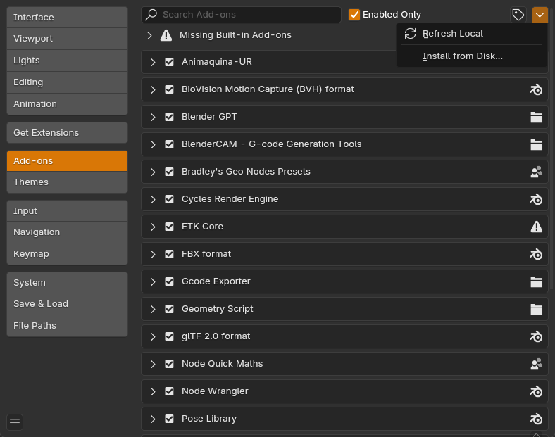
After adownloading open the settings / addons and clocl on install from file
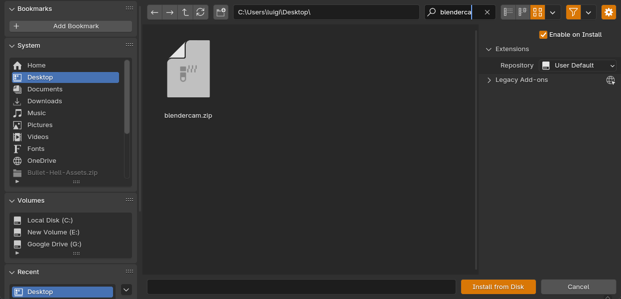
then select the zip for blendercam
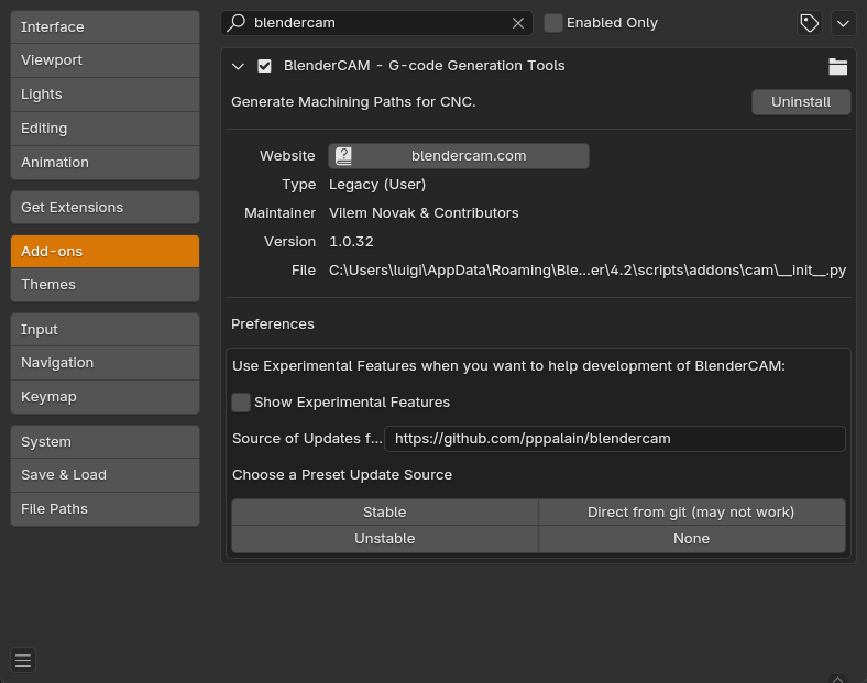
activate the addon:
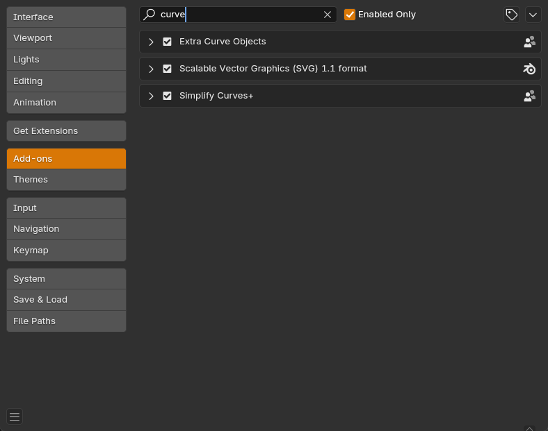
Now, there are two addons that you need to activate. Go to the settings, addons, and activate the curve tools, the extra curve objects, and the simplify curves+ addons. Restart Blender and everything should be working as expected.
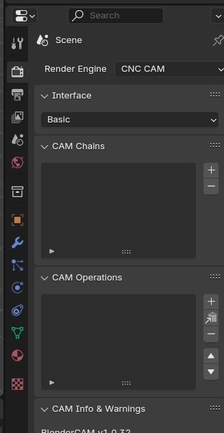
In the Blender properties, on the scene panel, you need to select BlenderCAM as a render. This will activate all the BlenderCAM functions.
After I installed it, I noticed that there were some Python libraries missing to get the curve tools working. To install these, I opened the text editor inside Blender and ran the following code to install each library. This runs a pip command to get the missing libraries. For this to work, Blender needs to be running as administrator:
1
2
3
4
5
6
7
8
9
10
11
12
13
14
15
| import subprocess
import sys
import os
# path to python.exe
python_exe = os.path.join(sys.prefix, 'bin', 'python.exe')
# upgrade pip
subprocess.call([python_exe, "-m", "ensurepip"])
subprocess.call([python_exe, "-m", "pip", "install", "--upgrade", "pip"])
# install required packages
subprocess.call([python_exe, "-m", "pip", "install", "shapely"])
print("DONE")
|
Then click on the play button next to the script name; this should install the Shapely library. After that, change this line:
1
| subprocess.call([python_exe, "-m", "pip", "install", "shapely"])
|
to the following :
1
| subprocess.call([python_exe, "-m", "pip", "install", "equation"])
|
This should install the Equation library.
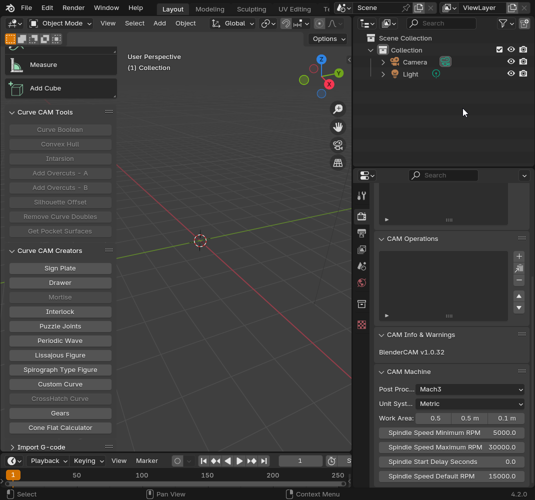
if all went good you should be all set:
For the 3D printed parts, I am using 3D printed surfaces. These surfaces are then sliced into many curves. Then I extract the top and bottom curves that will be used to generate milled contour to serve as an inset. I’m also adding a circle in the middle for the light to come through there.
Here is the initial design; for material, I am using some MDF.
The idea is that using the curve I can mill that and perfectly fit the printed part on the wood. Here is an initial test:
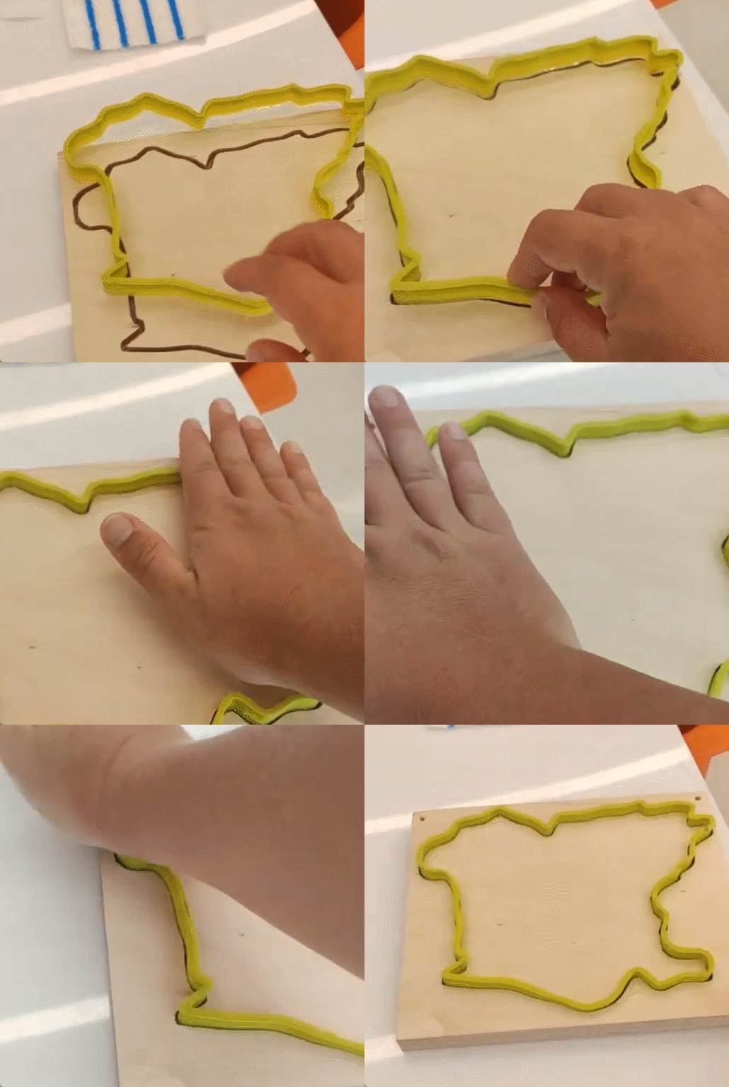
After making sure it fits, now it’s time to design the different vertical columns that will hold the wood bases.
BlenderCAM uses curves to generate the toolpath, so first, make sure that all the objects are converted to curves by using the convert to curve command in Blender.
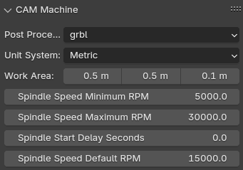
In the new CAM Machine panel, set the following:
- Post processor (depends on your machine)
- Machine size
- Spindle settings
Now you can select the curve you want to cut and position it inside the new box. This box represents your cutting area relative to your work offsets.
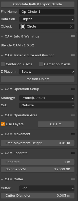
In this case, I chose the circle and clicked the + icon on the CAM operations. This will create a new operation.
New options should come up. You can set a name for the file and a name for the toolpath (on the same folder where your blend file is saved). Make sure the object matches the name of the curve you want to mill.
In my case, I leave the Z placement to below as I need to cut on the negative Z axis from my 0.
Select the operation; in my case, it’s a basic profile (cutout) and if you want to cut inside, outside, or on line.
Set the layers height; in our case, it’s how much we want to cut each time. A rule of thumb is 1 diameter of your mill bit.
Set the free movement height; this should be a safe distance over your stock.
Set the feed rate (depends on material and flutes).
Select a cutter type and diameter.
Finally, click on calculate path and export gcode. This will show you a preview of the path.
Milling
Make sure the Y axis are squared; in this case, I jogged the machine over the limit so it makes the Y axis parallel.
Home the machine.

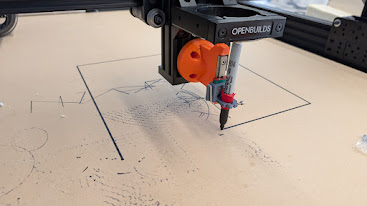
I first drew (with a pen) an outline of the boards with the CNC so I can perfectly align each board every time:
then i bolted some wooden boards to make a jig that holds the boards in place:
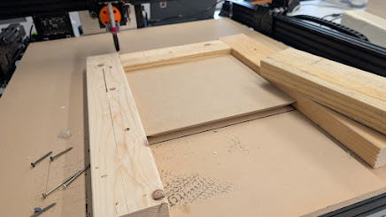
and a forth board that pressure holds the board:
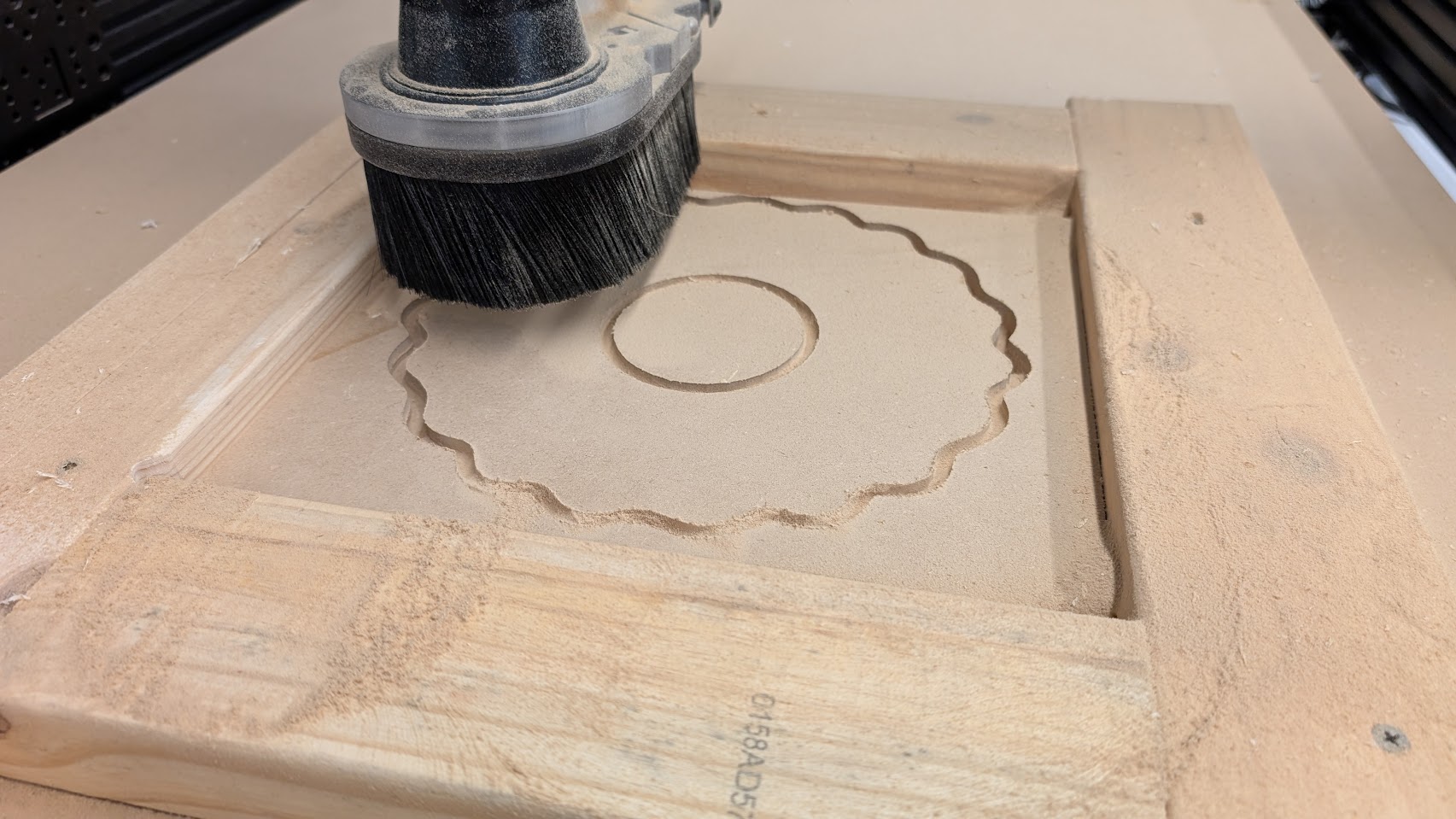
Now i can set the work offset bu jogging to the top left cornder and setting the x and y origin:
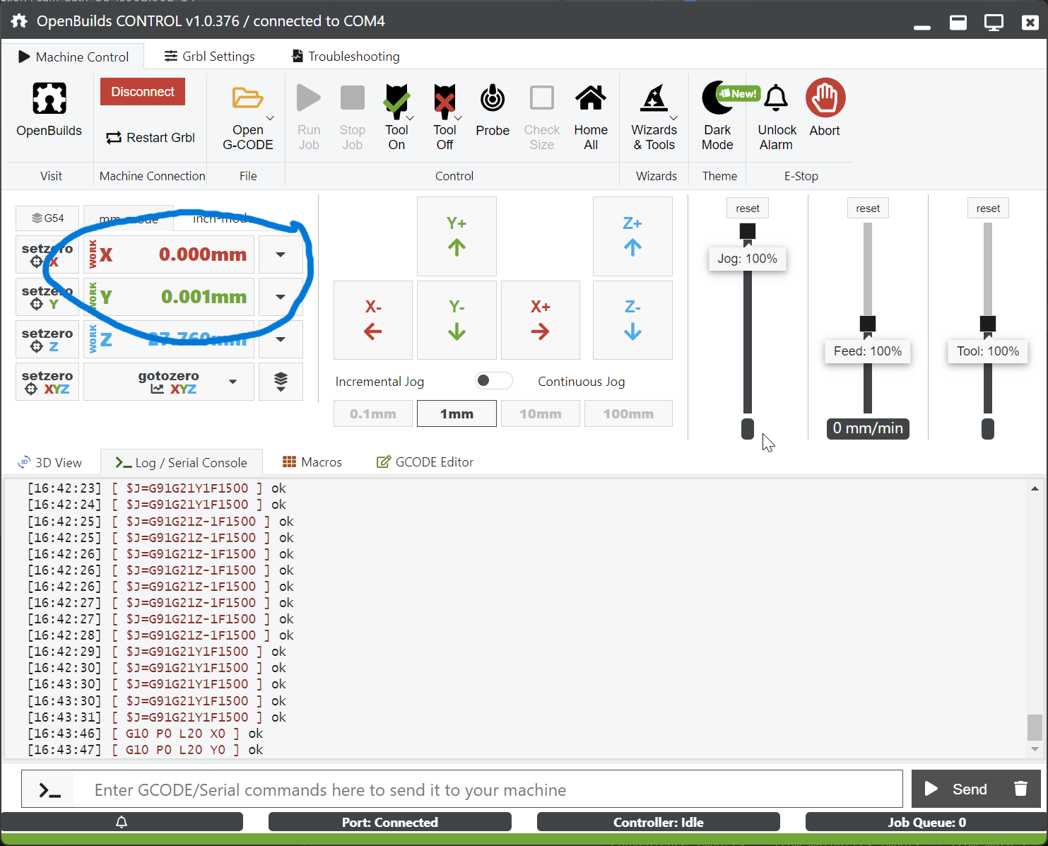
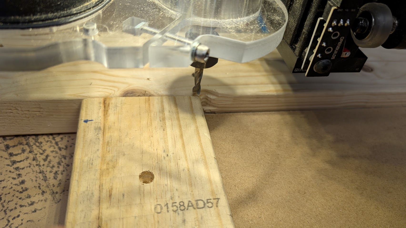
Then i do the same for the Z axis by jogging just on top of it:
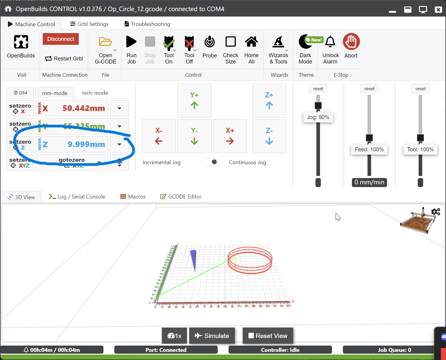
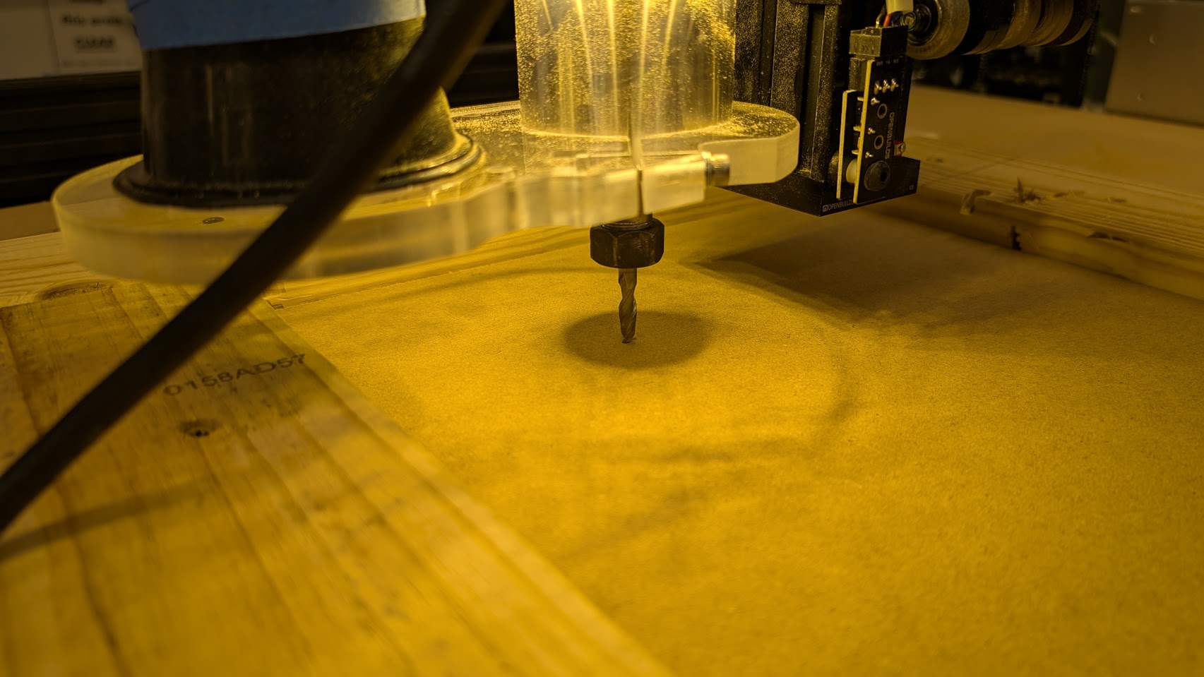
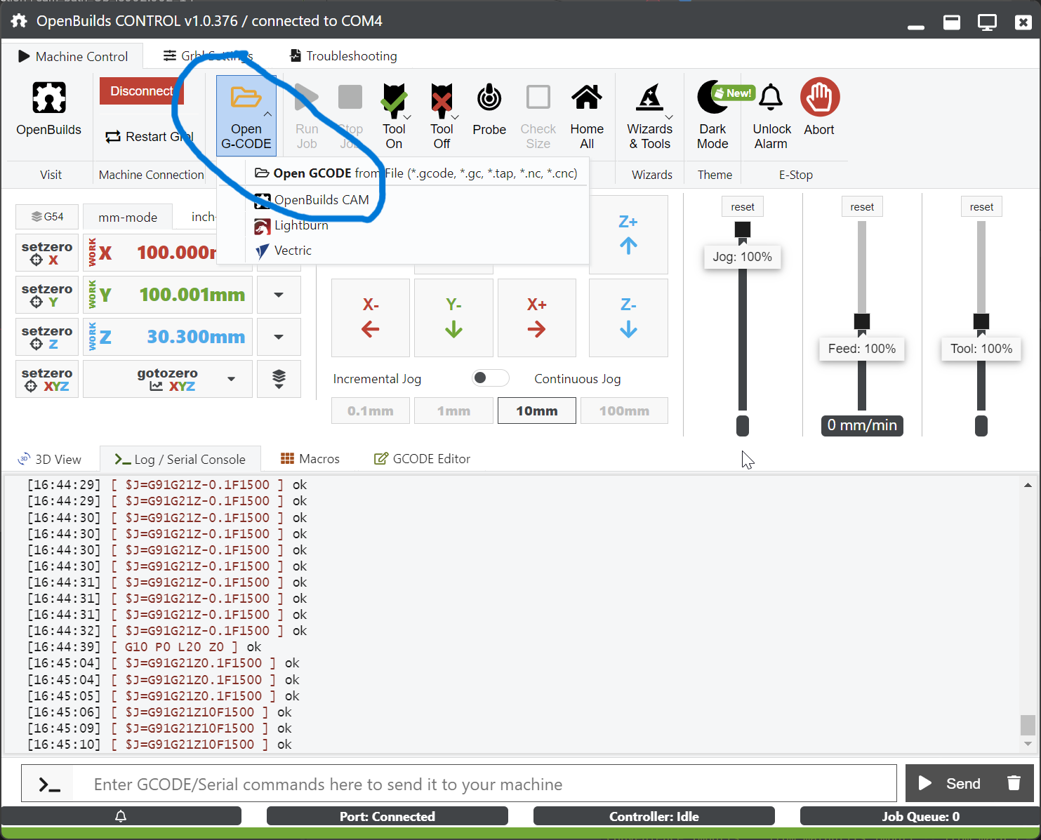
Now i can load a toolpath:
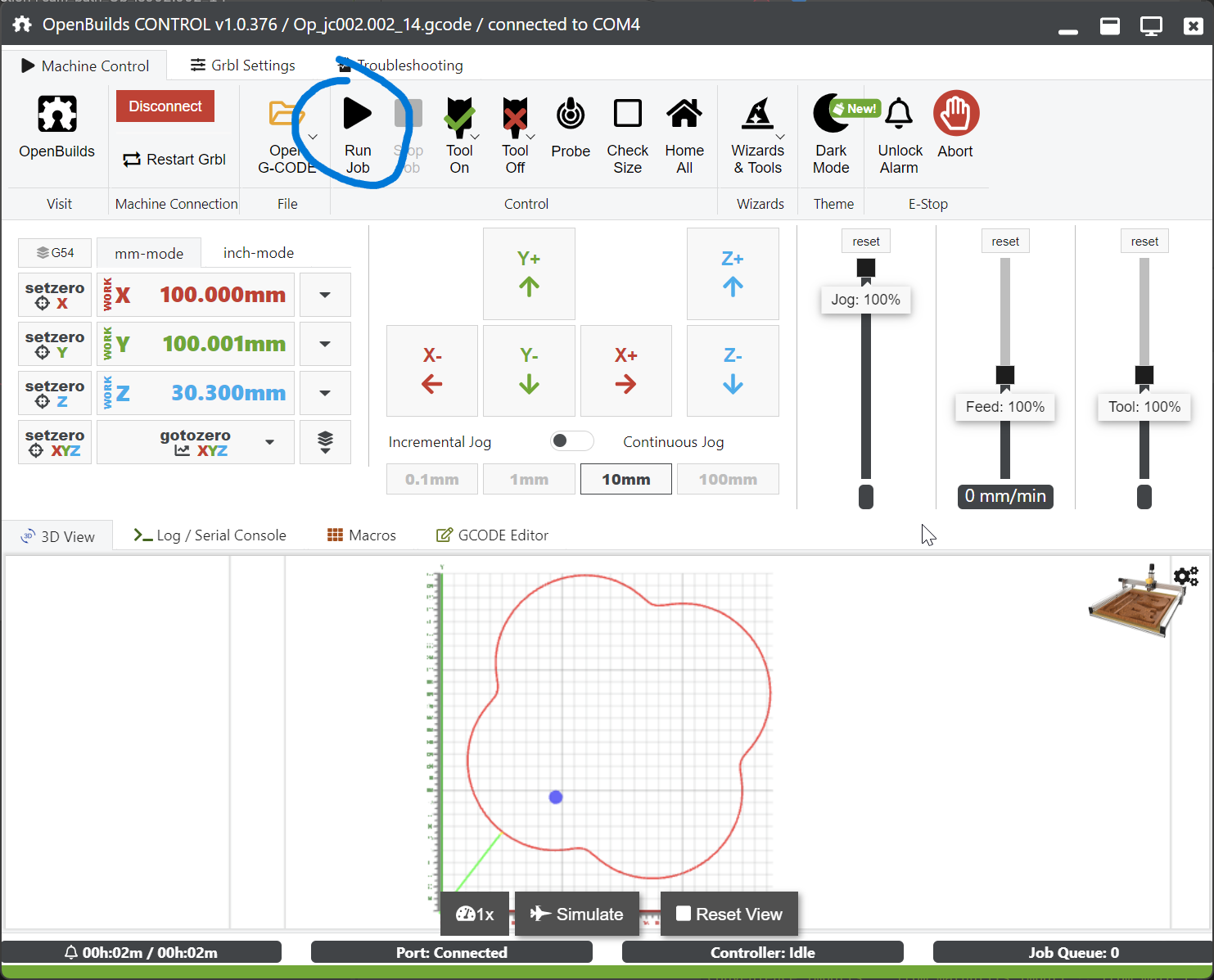
Turn on the spindle and the shop vac, Click on the run job:
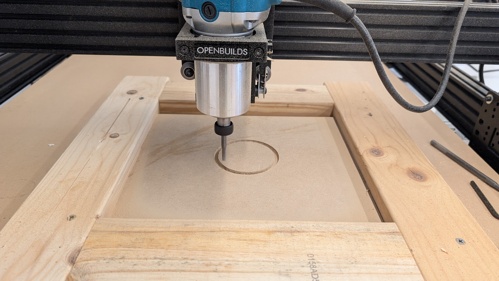
and the machine will cut your parts
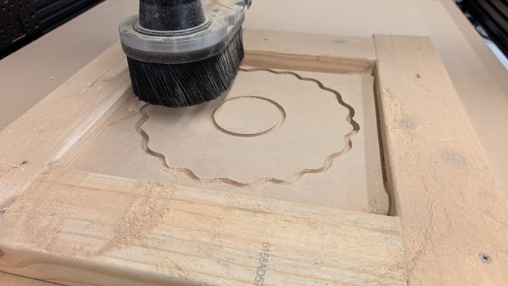

After validating that this worked, I printed the rest of the columns and cut the rest of the boards:
This is the final result:


Conclusion
I like this idea of using 3D printed parts to connect wood. Also, BlenderCAM had a lot more potential than I initially thought.I comes with some intresting curve tools like boolean operations, making boxes, jigsaw, etc. Making dogbones and other CNC specific objects should be straight forward with the overcut function. Enabling experimental allows to add 4th and 5th axis. I think this can be an intresting alternative for the pocketNC.
File
FILE