Final Project
Moi is a small air humidifier device that can be placed on a table in any interior. It is improving air quality in the area and also it’s serving as a lamp when LEDs are on.

Project tracking
What have been done / what haven’t been
-
Concept development
- Research
- Ideation
- Concept testing
Developed an idea of product, it’s purpose and function, considered possible electronics component which will be used, made a test board and tested components, figured out voltage consumption and control possibilities.
-
Design
- Industrial sketching
- Draft modeling in VR
- CAD modeling
I used 2D and 3D modeling capabilities for my project design. Used 2D to come up with ideas for product appearance as well to measure all the parts and components I use and to create full assembly in CAD program.
-
Fabrication
- 3D printing
- Laser cutting
I used additive and subtractive fabrication techniques for making different parst and assemby them to one integrated system with separated zones for water, air and electronics component.
-
Electronics production
- PCB design
- PCB milling
- Soldering
- System integration
Used PCB production tools in conjunction with CAD assembly to create a PCB with desired shape and dimentions. Made an according composition of components on the board to fit in the design. Made heating components upside down to pretend overheating in the narrow area and give more free space for cooling. Made an electronics box to cover all the electronics part and electronic devices in one integrated closed system.
-
Embedded programming
- Microcontroller programming
- Mobile application development
- Wireless control interface development
Wrote a program for microcontroller to control devices switching time. It’s still remaining to make a wireless control interface like mobile application.
-
Assembly
- Water isolation
- PCB isolation with epoxy
- Finishing
- Assembling
Used silicone sealant to isolate water tank. Cleaned 3D print supports, connected electronics and devices, assembled. It’s still remaining to make an epoxy cover on PCB to make sure it’s protected from water.
Project development
-
Tasks completed / not completed
- Water flow system
- PCBs for electronics devices control
- Power regulation
- Wireless control application
- Water refill hole
- PCB isolation with epoxy
-
What worked / what didn’t
- Mist maker switching control
- Pump works as the water runs out
- Addressable LEDs work programmed
- Voltage regulator overheats
- Mist maker pits and mist doesn’t reach high
- Piezoelectric mist maker disk
-
What questions need to be resolved
- Mobile application development
- Control over WiFi (add WiFi module)
- How to make the pump silent
- Replace mist maker device with piezoelectric mist maker disk
- How to make water refill hole and cap. What materials to use
Planning
-
Week 2
Sketched ideas, 3D modeled draft design.
-
Week 9
Tested out mist maker device, controlled with transistors.
-
Week 11
Made water level sensor with copper sheets and tested.
-
Week 13
Tested communication over WiFi. Between ESP12-F with wifi modules.
-
Week 14
Made a test interface in Blynk for mobile application and tested control ESP12-F over Wifi.
-
Week 16-20 - This page
Finished 3D model, started fabrication processes, made a final PCB, Programmed.
Process

Final project started with sketching ideas, where I approximately considered what it will be built from and what parts it will contain.

Draft 3D models were done in VR.

3D modeling and fabricating parts

I used Fusion 360 for making 3D model of my final project.
It consists of three 3D printed parts
- Water tank
Stores water and integrates a mist maker for creating a cool mist. A designated filling port on the bottom allows for refilling water. It’s connected to acrylic sheet and isolated from bottom parts. 3D Printed Construction: The tank is 3D printed with translucent material, allowing for a unique aesthetic and for internal light features. 3D printed with variable layer heights between 0.2mm and 0.8mm. This optimizes material usage and potentially enhances strength or visual effects. The translucent material reflects light from internal sources, creating an attractive illuminated effect. The center of the tank incorporates a dedicated area for connecting a mist maker device. This includes: Pipe connection point for water delivery to the mist maker. Also through central part is dedicated space for sensor wires and mist maker’s connection wires.
- Electronics box
Includes in it PCB, big components are fitted in this part: mist maker device, water pump. Special space is dedicated for THT transistors, voltage regulator, connection jack and connectors and microcontroller. Part is 3D printed, fits in bottom case, has parts for screwing to the acrylic sheet above it.
- Bottom case
3D printed with special texture, reached with slicing setting fuzzy skin, connects to the water tank with thread, Provides a connection to the power jack from outside.

Water tank and bottom case have a joining with thread. It’s 90 degree rotation for full close. For this parts I tested thread with different offsets and final version was 0.8 mm total.
Water tank and bottom case
Electronics box part.

Lasercutting
Laser cut acrylic sheet which fits into bottom part of water tank and connects with silicone sealant. For better adhesion of sealant here is done engravings along the edges.

Post-processing
Prepared 3D printing with silicone for preventing leaking. because wall thickness was 2 layers 0.8mm = 1.6mm

Mist maker fixed on water tank.

Here connects the acrylic sheet.

Isolated with silicone sealant
PCB production
I have already tested mist maker, pump and voltage regulation on test board. This time I decided to use RP2040. amount of pins on this board was enough to control all devices and sensors. Here is a schematic.


Microcontroller:
- Seeed XIAO RP2040
Inputs:
- Capacitive touch
- Resistive touch x2
Outputs:
- Fogger
- PUMP
- addressable LEDs
Communication:
- Bluetooth module
Power:
- 24V input
- Voltage regulator 24V to 5V
Designed the board with using all pins of the microcontroller. Some of connections are used, some are designed for any case like capacitive touch connection, bluetooth connection and clock/data connections.
Designed PCB according the shape of electronics box. It’s circle shaped, there is a space for mist maker to fit in the middle gap part. PCB is from 2 pieces. The reason of it was that if some of parts will not work, to change not all PCB but one part of it, and also the biggest size of our copper plate was 7x10 cm, so I used two of these.

Two parts will be connected to each other with connectors. Here is one of them.

And connected both parts.

This PCB contains addressable LEDs, which are soldered right on the board. Thats why right above the PCB is transparent acrylic sheet. And on top side of PCB there would be no space to solder big components. That’s why I designed this board to be some kind of two sided and THT components and microcontroller are soldered upside down.

This not only saves space above the PCB but also prevents these component from being overheated.
Programming
The microcontroller used in the project is Seeed Xiao RP2040.
Outputs
- Addressable LED 5 V

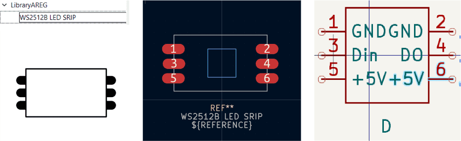
For lighting is used addressable led strip. LEDs are separated from the strip and arrayed on the PCB on a particular distance. For using LEDs separated from the LED strip Areg created footprint for KiCad with according sizes. Download link.
This LEDs in my project are programmed by using Adafruit NeoPixel library. Download link.
- Ultrasonic mist maker 24 V

With some tests I find out how this device works. It has water level sensor on it as well that’s why I needed to make this part to be sealed in the water. And what shows this test the sensor and the piezo disc parts need to have conduction through water.
I wanted to make the mist coming from piezo element part to rise into the air. that’s why I designed the water tank to have empty space in the middle. The challenge was keeping the water level in the container full and preventing water from getting in the middle part through the fogger’s holes. For keeping low water level in that middle part I used pump and pipes.
- Water pump 3-5 V.

This pump can be sealed in the water. But for aesthetic purposes I din’t wat it to be visible in the water tank through transparent material.
I also used a pump to pump a small amount of water into the fog machine. I did this because I couldn’t submerge the entire fogger in water and had to separate the main water container and the fogger. And with the help of a pump, I connected these two spaces to control the amount of water entering the fogger.
Input - resistive sensor
I also added a resistive sensor to automate this process. Sensor detects when water is low. It’s two wires, one placed in the maximum water level needed, the other in the lowest part.
In simple words, when there was no water above fogger, my device recognized this and supplied water, and when the water rose to the maximum level and contacted the resistive sensor, the supply stopped until it completely evaporated.
            #include <Adafruit_NeoPixel.h> // Adafruit library
            #ifdef __AVR__
            #include <avr/power.h>  // Required for 16 MHz Adafruit Trinket
            #endif

            #define PIXEL_PIN 29  // Pin to control NeoPixels.
            #define PIXEL_COUNT 6  // Number of NeoPixels

            #define pumpPin 2 // Pin to control water pump
            #define foggerPin 4 // Pin to control Mist maker device
            #define sensorPin 26 // Pin wired to insput

            // Declare our NeoPixel strip object:
            Adafruit_NeoPixel strip(PIXEL_COUNT, PIXEL_PIN, NEO_GRB + NEO_KHZ800);
            // Argument 1 = Number of pixels in NeoPixel strip
            // Argument 2 = Arduino pin number (most are valid)
            // Argument 3 = Pixel type flags, add together as needed:
            //   NEO_KHZ800  800 KHz bitstream (most NeoPixel products w/WS2812 LEDs)
            //   NEO_KHZ400  400 KHz (classic 'v1' (not v2) FLORA pixels, WS2811 drivers)
            //   NEO_GRB     Pixels are wired for GRB bitstream (most NeoPixel products)
            //   NEO_RGB     Pixels are wired for RGB bitstream (v1 FLORA pixels, not v2)
            //   NEO_RGBW    Pixels are wired for RGBW bitstream (NeoPixel RGBW products)

            boolean oldState = HIGH;
            int mode = 0;  // Currently-active animation mode, 0-9

            unsigned long currentMillis = 0;


            int pumpOnTime = 2000;
            bool isPumpOn = false;
            int sensorThreshold = 400;

            void setup() {
            strip.begin();  // Initialize NeoPixel strip object (REQUIRED)
            strip.show();   // Initialize all pixels to 'off'
            rainbow(10);

            pinMode(sensorPin, INPUT); // Defined as input
            pinMode(pumpPin, OUTPUT); // defined as output
            currentMillis = millis();

            pinMode(foggerPin, OUTPUT);
            digitalWrite(foggerPin, HIGH); // Fogger state ON
            }

            void loop() {
            int sensorVal = analogRead(sensorPin);  // read values from sensor
            //Serial.println(sensorVal);
            if (sensorVal < sensorThreshold && !isPumpOn) { // when sensor value is low then threshold turn on pump
                isPumpOn = true;
                Serial.println("pump off to on");
                digitalWrite(pumpPin, HIGH);
                currentMillis = millis();
            }
            // Get current button state.
            if (isPumpOn) {
                if (millis() - currentMillis > pumpOnTime) { // measure time the pump is on and turn off after 2 seconds.
                isPumpOn = false;
                Serial.println("pump on to off");
                digitalWrite(pumpPin, LOW);  // Pump OFF
                }
            }


            if (++mode > 8) mode = 0;  // Advance to next mode, wrap around after #8
            switch (mode) {            // Start the new animation...
                case 0:
                colorWipe(strip.Color(0, 0, 0), 50);  // Black/off
                break;
                case 1:
                colorWipe(strip.Color(255, 0, 0), 50);  // Red
                break;
                case 2:
                colorWipe(strip.Color(0, 255, 0), 50);  // Green
                break;
                case 3:
                colorWipe(strip.Color(0, 0, 255), 50);  // Blue
                break;
                case 4:
                theaterChase(strip.Color(127, 127, 127), 50);  // White
                break;
                case 5:
                theaterChase(strip.Color(127, 0, 0), 50);  // Red
                break;
                case 6:
                theaterChase(strip.Color(0, 0, 127), 50);  // Blue
                break;
                case 7:
                rainbow(10);
                break;
                case 8:
                theaterChaseRainbow(50);
                break;
            }

            delay(2000);
            }

            // Fill strip pixels one after another with a color. Strip is NOT cleared
            // first; anything there will be covered pixel by pixel. Pass in color
            // (as a single 'packed' 32-bit value, which you can get by calling
            // strip.Color(red, green, blue) as shown in the loop() function above),
            // and a delay time (in milliseconds) between pixels.
            void colorWipe(uint32_t color, int wait) {
            for (int i = 0; i < strip.numPixels(); i++) {  // For each pixel in strip...
                strip.setPixelColor(i, color);               //  Set pixel's color (in RAM)
                strip.show();                                //  Update strip to match
                delay(wait);                                 //  Pause for a moment
            }
            }

            // Theater-marquee-style chasing lights. Pass in a color (32-bit value,
            // a la strip.Color(r,g,b) as mentioned above), and a delay time (in ms)
            // between frames.
            void theaterChase(uint32_t color, int wait) {
            for (int a = 0; a < 10; a++) {   // Repeat 10 times...
                for (int b = 0; b < 3; b++) {  //  'b' counts from 0 to 2...
                strip.clear();               //   Set all pixels in RAM to 0 (off)
                // 'c' counts up from 'b' to end of strip in steps of 3...
                for (int c = b; c < strip.numPixels(); c += 3) {
                    strip.setPixelColor(c, color);  // Set pixel 'c' to value 'color'
                }
                strip.show();  // Update strip with new contents
                delay(wait);   // Pause for a moment
                }
            }
            }


            void rainbow(int wait) {   // Rainbow cycle along whole strip. Pass delay time (in ms) between frames.
            // Hue of first pixel runs 3 complete loops through the color wheel.
            // Color wheel has a range of 65536 but it's OK if we roll over, so
            // just count from 0 to 3*65536. Adding 256 to firstPixelHue each time
            // means we'll make 3*65536/256 = 768 passes through this outer loop:
            for (long firstPixelHue = 0; firstPixelHue < 3 * 65536; firstPixelHue += 256) {
                for (int i = 0; i < strip.numPixels(); i++) {  // For each pixel in strip...
                // Offset pixel hue by an amount to make one full revolution of the
                // color wheel (range of 65536) along the length of the strip
                // (strip.numPixels() steps):
                int pixelHue = firstPixelHue + (i * 65536L / strip.numPixels());
                // strip.ColorHSV() can take 1 or 3 arguments: a hue (0 to 65535) or
                // optionally add saturation and value (brightness) (each 0 to 255).
                // Here we're using just the single-argument hue variant. The result
                // is passed through strip.gamma32() to provide 'truer' colors
                // before assigning to each pixel:
                strip.setPixelColor(i, strip.gamma32(strip.ColorHSV(pixelHue)));
                }
                strip.show();  // Update strip with new contents
                delay(wait);   // Pause for a moment
            }
            }

            // Rainbow-enhanced theater marquee. Pass delay time (in ms) between frames.
            void theaterChaseRainbow(int wait) {
            int firstPixelHue = 0;           // First pixel starts at red (hue 0)
            for (int a = 0; a < 30; a++) {   // Repeat 30 times...
                for (int b = 0; b < 3; b++) {  //  'b' counts from 0 to 2...
                strip.clear();               //   Set all pixels in RAM to 0 (off)
                // 'c' counts up from 'b' to end of strip in increments of 3...
                for (int c = b; c < strip.numPixels(); c += 3) {
                    // hue of pixel 'c' is offset by an amount to make one full
                    // revolution of the color wheel (range 65536) along the length
                    // of the strip (strip.numPixels() steps):
                    int hue = firstPixelHue + c * 65536L / strip.numPixels();
                    uint32_t color = strip.gamma32(strip.ColorHSV(hue));  // hue -> RGB
                    strip.setPixelColor(c, color);                        // Set pixel 'c' to value 'color'
                }
                strip.show();                 // Update strip with new contents
                delay(wait);                  // Pause for a moment
                firstPixelHue += 65536 / 90;  // One cycle of color wheel over 90 frames
                }
            }
            }
I also made a second version of the code where I could control the feed without using a sensor. To do this, I measured the time for complete evaporation of one portion of water and thus made a delay timer for water supply and evaporation. It took 1 second to serve and 9 seconds to evaporate.
void loop() {
  digitalWrite(pumpPin, HIGH);
  digitalWrite(foggerPin,HIGH);
  delay(1000);
  digitalWrite(foggerPin,LOW);
  digitalWrite(pumpPin, LOW);
  delay(9000);
}
BOM
| Qty | Description | Price | Link | Notes |
|---|---|---|---|---|
| 1 | Fog maker | 11.00 $ | amazone link | |
| 1 | Water pump | 7.39 $ | amazone link | |
| 1 | Pipe | 0.5$ | from lab | diameter 8 mm, ~ 50cm lenght |
| 1 | Silicone sealant | 5.00 $ | from lab | |
| 1 | Filament | ~15$ | from lab | |
| 2 | Copper Clad Laminate PCB 7x10cm | 0.90 $ | aliexpress link | |
| 1 | Seeed XIAO RP2040 | 5.40 $ | official page store | |
| 1 | Acrylic sheet | 5$ | from lab | 4.8mm thickness, 20x20cm |
| Electronics components | ~ 5$ | from lab | ||
| Total | 45.99$ |
Licensing
MOI by Elen Grigoryan is licensed under CC BY-NC-SA 4.0![]()
![]()
![]()
![]()