Electronics Production
Scheduling
This week was Electronics Production week, and I’ve heard from my seniors and previous Fab academy alumni that this week is when the pace begins to speed up. So I started off my project by working out my schedule for the week, while also accounting for my school schedule.

Individual Assignment
The Quentorres Board
This week, we were assigned to make and test a microcontroller development board. However, we didn’t have to design a new board online. This is where the Quentorres Board comes in. The Quentorres is a programmer created by Quentin Bolsée and redesigned by Adrián Torres. You can learn more about the Quentorres here ).
Here is a list of all of the components you’ll need to create the board.
I started off by downloading the PNG files at the bottom of the documentation page. I decided to make a small modification to this design (sorry Adrian), and added my initials at the bottom of the board.

I used Inkscape for this process.
After I was done, I exported my files from Inkscape as SVG files. However, they need to be RML files for the milling process. So I moved onto mods CE.
Mods CE
mods CE (community edition) is a fork of CBA mods research project. mods is a modular cross platform tool for fablabs. It is based on independent but interrelated modules.
Our local instructor introduced this software to us in the past, so I was quite comfortable with navigation. However, here are the steps that I followed to prep my files for milling.
- Open the mods CE website.
-
After opening the page, do the following:
right-click> programs> open program> mill 2D PCB
(This last step can differ based on your local milling machine)

-
The following page should open up.

If it does, follow the instructions as shown below.

Adding a new program
if you’re still unsure of step 4, you can follow these instructions:
- right-click
- click on “modules”
- click on “add module”
-
click on “save” under the “file” tab

4. After you’ve followed the steps, your page should look something like this.

-
Click on calculate. If you’ve done everything correctly, your file should start downloading. Here’s a nice visualization of what a g-code looks like.

Milling
After I finished modding my files and they were all RML files, I started milling. I went over to the milling machine that we have at our Fab Lab (the monoFab SRM-20).
I unscrewed the base plate, and then removed the sacrificial layer. However, we were out of the regular tape that we use at our Fab Lab, so we thought took this as an opportunity to test out different materials.
At first, we used heavy duty double-sided tape, however, this was a bit too strong and made it really hard to remove the printed circuit from the sacrificial layer (This caused a bit of a problem when we were designing our in-house design rules for the group assignment.) Then, we decided to use epoxy tape, and it worked perfectly.
After the bed was set, I set up the milling machine, and started cutting out my files.


Soldering
Once the milling was complete, I started soldering.
To start off, I made my own component list.

After confirming that I had all of the required components, I started to solder.
I used the Quentorres page as a reference.
This was the final result.

Programming
Now that I had a soldered board. I started my programming. I followed the Quentorres page to program my board, since all of the steps were nicely documented on there. However, if you’d like to follow along with me, here’s what I did.
The Seeed Studio XIAO RP2040 Pins
I started off by checking out the pin out diagram for the Seeed Studio XIAO RP2040.
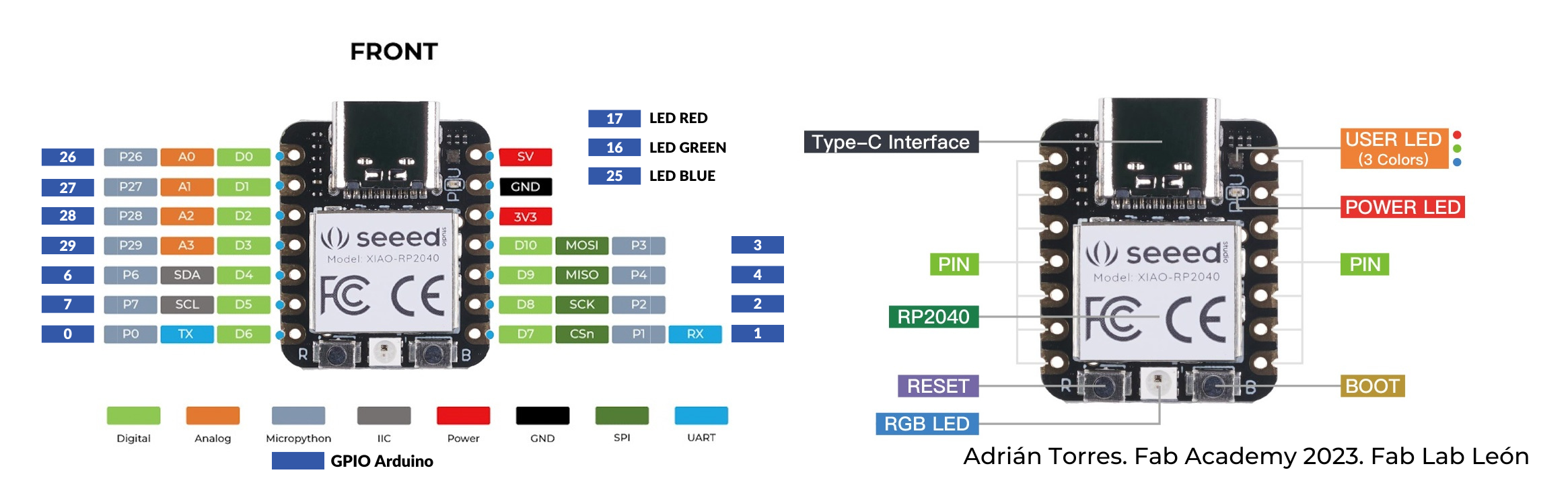

Arduino IDE
I programmed the board using Arduino IDE. I’ve used this in the past, so I already had it downloaded. But if you don’t, you can download the software here, and follow the instructions on the page (it’s really user-friendly).
The software doesn’t have ALL the information required to program the board just yet, so we’ll need to add that information. For this project, I’ll need the Arduino Pico by Earlephilhower. So, I opened Arduino IDE, and went to File> Preferences.
In the Additional Boards Managers URLs: tab, enter the following links:
https://github.com/earlephilhower/arduino-pico/releases/download/global/package_rp2040_index.json

https://raw.githubusercontent.com/espressif/arduino-esp32/gh-pages/package_esp32_index.json
Then, we’ll need to download the Pico board manager (like I said mentioned earlier). Navigate there by going to Tools> Board> Board Manager (or CTRL+SHIFT+B on Windows).
In the searchbar, enter “Pico”, and then select the Pico/RP2040 manager.
Now, we’ll need to configure the software to be compatible with the Seeed Studio XIAO RP2040.
Go to Tools> Board> Raspberry Pi Pico/RM2040> Seeed XIAO RP2040.

Now, we’ll need to load the blink program.
On the Quentorres board, the LEDs are connected to pins 0, 1, and 26. For now, we want to test out the LED that’s connected to pin 26, so we’ll replace all the LED_BUILTIN variables with the pin number that we’d like to test (in this case, 26).

Here’s the code incase you’d like to replicate it:
// the setup function runs once when you press reset or power the board

void setup() {
  // initialize digital pin LED_BUILTIN as an output.
  pinMode(LED_BUILTIN, OUTPUT);
}

// the loop function runs over and over again forever
void loop() {
  digitalWrite(LED_BUILTIN, HIGH);  // turn the LED on (HIGH is the voltage level)
  delay(1000);                      // wait for a second
  digitalWrite(LED_BUILTIN, LOW);   // turn the LED off by making the voltage LOW
  delay(1000);                      // wait for a second
}
Output
Here’s the output
After this, I did the same for pins 1 and 0
 Here’s how they came out
I also decided to show the different LEDs in one video
The Mentioned Files
Quentorres Drill

Quentorres Interior

Quentorres Modified

This website was created using a template provided by Mr. Anith Ghalley and was used with his permission.*