Computer-Controlled Cutting
Scheduling
I started my week off (as always,) by creating a schedule and planning out my time. This week, I only tracked my Fab Academy related activities.

The Vinyl Cutting Machine
A vinyl cutting machine is something that you’ll find in almost every Fab Lab. It cuts adhesive vinyl sheets into shapes for crafts, signs, and designs. It’s simple to use and popular for making custom stickers, decals, and apparel graphics.
At our Fab Lab, we have one vinyl cutting machine, that is characterized by the following:
- Model: Roland CAMM-1 GS-24
- Software: Roland CutStudio and Adobe Illustrator
- Cutting area: Maximum 584 mm × 25000 mm
- Maximum material thickness: Around 2.5 mm (0.1 inches)
- Cutting speed: 10 to 500 mm/s (all directions)
- Usable tools: Roland CAMM-1 series blade
- Settings:
- Textile Vinyl: Speed: 15 cm/s / Force: 90gf
- Copper Vinyl: Speed: 1 cm/s / Force: 40gf

Your Safety
- The vinyl cutter uses very sharp blades to do its job, this can be quite dangerous if the machine is used inappropriately, or left unattended.
- ALWAYS wear appropriate safety gear, including gloves and safety glasses, when operating the vinyl cutter.
- Keep your fingers and hands clear of the cutting area at all times, especially when the machine is in motion.
- Never leave the vinyl cutter unattended while it is in operation (This is a rule of thumb for most Fab Lab machines)
- Familiarize yourself with emergency shutdown procedures in case of any unexpected incidents.
- Regularly inspect the machine for any signs of wear or damage and perform maintenance as necessary.
- Keep the vinyl cutter out of reach of children and unauthorized users (especially in school settings like our school).
- In case of doubt or uncertainty, prioritize safety and seek guidance from experienced users or professionals (such as your local instructor or an experienced adult).
Vinyl Cutting
I decided to use the logo that I made last week, since it was relevant to my final project and i liked the way it looked.
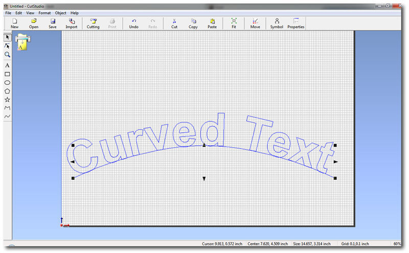
I started by importing my image onto Cutstudio using the import fool in the file tab.
Then, just CTRL+P to cut out the sticker.
Weeding
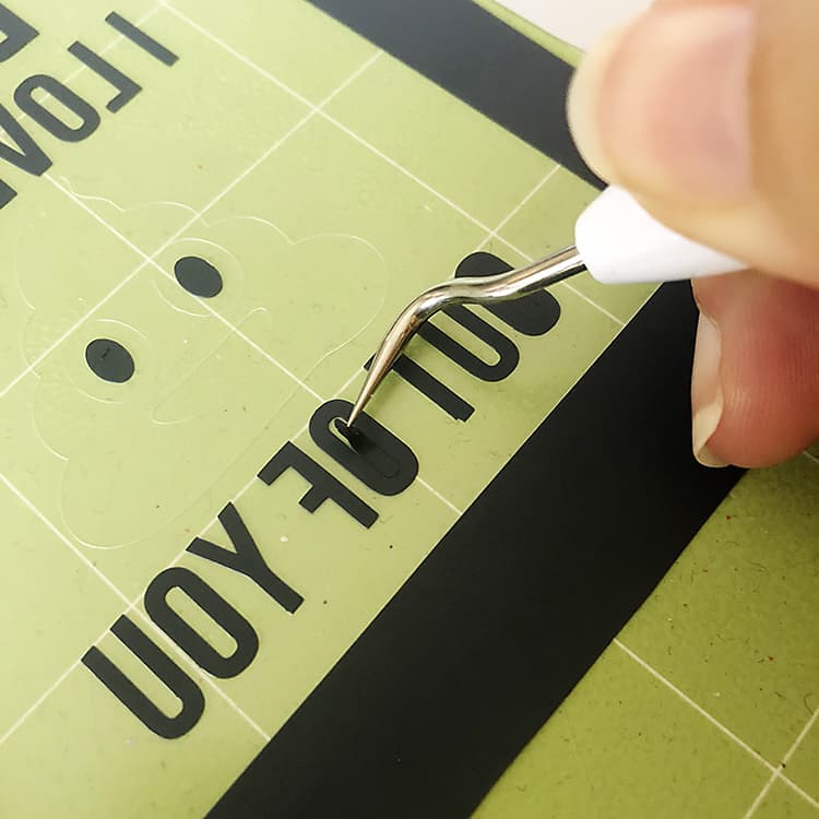
Weeding basically refers to the process of removing the excess vinyl material from around the design or lettering that has been cut by the vinyl cutting machine.
This excess material is typically referred to as the “negative space” or “waste material.” Weeding is necessary to reveal the desired design or lettering on the vinyl sheet.Here’s how the weeding process typically works: - After the vinyl cutting machine has finished cutting the design, the vinyl sheet is removed from the machine. The excess vinyl material surrounding the design is carefully peeled away by hand or using a weeding tool. The goal is to remove all the unwanted vinyl while leaving behind the desired design intact on the backing material.

- thebestvinylcutters.com
Transferring
Transferring, also known as “application” or “transfer tape application,” is the process of transferring the cut vinyl design from its backing material to the desired surface, such as a wall, window, or product. - After weeding, transfer tape is placed over the vinyl design, pressed firmly to adhere it securely. The backing material is peeled away, leaving the design on the transfer tape. It’s then carefully positioned on the surface and pressed with a squeegee for good adhesion. Finally, the transfer tape is peeled away, leaving the design securely in place.
Here’s how it came out:

If you’re still confused, you can follow this video tutorial, which I found really helpful !!!
Extra Information
There’s a lot of different vinyl cutting machines, and some details may differ from machine to machine, but I found a pretty general diagram on the User Manual for the GS-24 Vinyl Cutter.


When setting up your own vinyl cutter, I found the User Manual from earlier to be quite useful (they included detailed images and instructions).
Parametric Construction Kit
For this week, we had to create a Parametric Construction Kit, which is basically a customizable set of pieces that fit tightly together without glue or screws, allowing for easy assembly of various structures.
What makes something parametric though? The term “parametric” basically refers to a design approach where geometric parameters can be adjusted to create variations in size of a model or structure. Parametric design allows for flexibility and adaptability in design creation.
I wanted to create something that would mainly assemble into a plant, but also other random objects if required. I decided to use Fusion360 to create my designs.
Design Process
I started off by setting up my user parameters, and then creating a new sketch, and then drawing 2 circles. I added a singular rectangle (to create the slot), and then I used the “circular pattern” feature to multiply it. To find the user parameter tab, open the Modify dropdown tab, and then press User Parameters.
After consulting my local instructor, I found out that the cardboard I’d be using would be 4mm, so I made a parameter for the material thickness. Then I added one for the machine kerf, which we learned about in the group assignment, and then finally, I added a parameter for the finger joints, which would be
material thickness - my kerf value.


After that, I selected the faces that I needed, and then extruded it by my cardboard thickness.
To create the triangles, I sketched a simple triangle, and then drew a square with the slot dimensions.

Then, I used the circular pattern to duplicate it onto the other sides.

However, since the origin wasn’t the center, the duplicated slots were misaligned, so I used the midpoint constraint to fix that issue.

To extrude, I selected everything except for the slots, and extruded my selection by the cardboard_thickness parameter (4 mm).
The pentagon was similar to the triangle, I created a sketch, and then added a square on one side, which I constrained to the midpoint of it’s respective side.

I used the pattern feature to duplicate onto the other sides, and then I extruded the shape with the cardboard_thickness parameter.

After I had finished my designs, I decided to chamfer the slots. This is was advice that I got from the Global Open Time, and can add efficiency to my designs by making assembly and disassembly easier.

I opened the “chamfer” feature in the “modify” section, and then selected all of my slot corners that were inwards facing. I changed the chamfer value to my slot/2 (2 mm), and then pressed enter.

This is a before and after picture of the chamfer process.
Then, I needed to export my design in the form of a 2D file, so I selected the top face of whatever I wanted to export.

I projected this selection and then pressed enter.

After I had my projections, I hit the bodies just to make sure. I then opened my sketches tab, and right clicked on the most recent sketch (which should be your earlier projection), and the “Save As DXF” option should appear.

If you’d like to turn your file into an SVG, you can export the file to your desktop, upload it to Inkscape, and then format it on there (that’s what I did).
Cutting & Assembly
After that, I cut out my SVG file using our local laser cutter.
Once you have your design open on Inkscape, simply click CTRL+P, and select your laser printer.

Depending on the software you’re using, your UI will be different. Here’s what mine looks like:

note; if you’re having a hard time navigating, I found this website REALLY useful.
(The settings are 15% speed and 100% power)

After that, I was able to assemble my design into multiple shapes! However, these 2 were my favourites:
 (A Rafflesia Arnoldii but with a bit of technology)
 (A robot starfish)
The Mentioned Files
*This website was created using a template provided by Mr. Anith Ghalley and was used with his permission.

