Measure the power consumption of an output device.
Document your work on the group work page and reflect on your individual page what you learned.
Measuring power consumption is a crucial aspect of assessing the energy efficiency and performance of electrical or electronic devices. Power consumption refers to the rate at which energy is used by a device and is typically measured in watts (W) or milliwatts (mW).
To measure power consumption, you need a power meter or wattmeter, which is a device that can measure electrical power. The basic idea is to measure the current (in amperes, A) flowing through a device and the voltage (in volts, V) across it. With these measurements, you can calculate power using the formula:
Power (P) = Voltage (V) × Current (I) Power (P)=Voltage (V)×Current (I)
For our group assignment this week, we measured the power consumption of a LED.
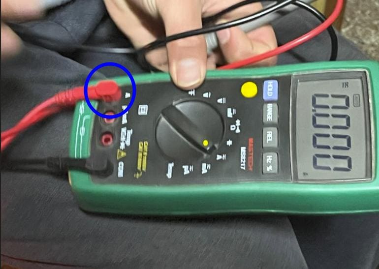
Note: We must always measure in series, that is, the circuit will be closed through the multimeter, so we must connect it correctly and always on a high scale or where we have the protection fuse (normally 10A).
Equipment Needed:
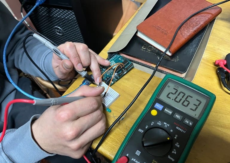
After gathering all the components, we made the components connection in series where we kept the main power supply from the Arduino which was connected to the CPU.
First we have to turn the multimeter dial to the Ammeter mode.
Then we checked the current from the CPU without any LED or resistors and it was around 2.063 A
Then we tried with the LED:
Connect the positive terminal of the power source to the anode (+) of the LED.
Connect the negative (black) probe of the multimeter to the negative terminal of the power source, completing the circuit through the multimeter.
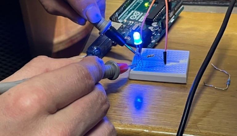
Turn on the power source and allow the LED to illuminate fully.
Observe and record the current reading on the multimeter. This is the operating current of the LED.
Calculate Power Consumption:
If you know the voltage across the LED setup (e.g., 3V for many standard LEDs), you can calculate the power consumption using the formula P = V * I, where V is the voltage and I is the current.
For example, if the voltage across the LED is 3V and the measured current is 10mA (0.01A), then P = 3V * 0.01A = 0.03W or 30mW.
Repeat and Average (Optional):
Add an output device to a microcontroller board you've designed and program it to do something.
Learning outcomes:
Demonstrate workflows used in controlling an output device(s) with MCU board you have designed.
Requirements for the documentation:
Linked to the group assignment page.
Documented how you determined power consumption of an output device with your group.
Documented what you learned from interfacing output device(s) to microcontroller and controlling the device(s).
Linked to the board you made in a previous assignment or documented your design and fabrication process if you made a new board.
Explained the programming process/es you used.
Explained any problems you encountered and how you fixed them.
Included original source code and any new design files.
Included a ‘hero shot’ of your board.
In the board that I made last week I didn't have the pin connectors for the I2C module and it only had the LED and a tactile push button which I didn't need for my final project. So I designed a new board this week and the processes are quite the same.
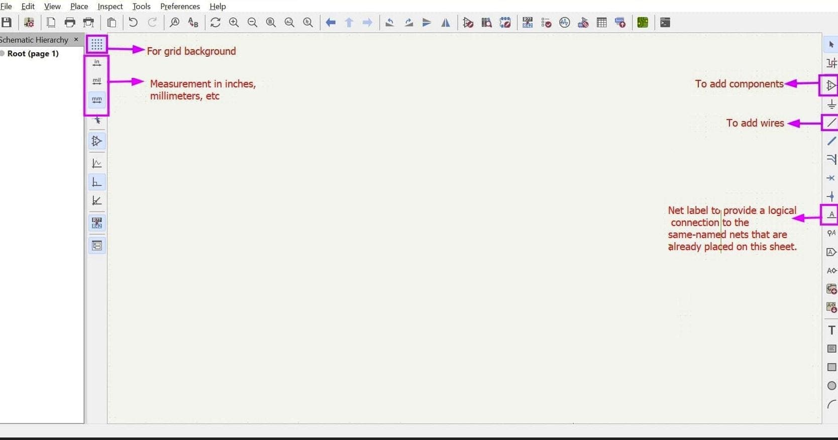
First I made the schematic design of my board.
Here is a basic user interface of the schematic KiCad.
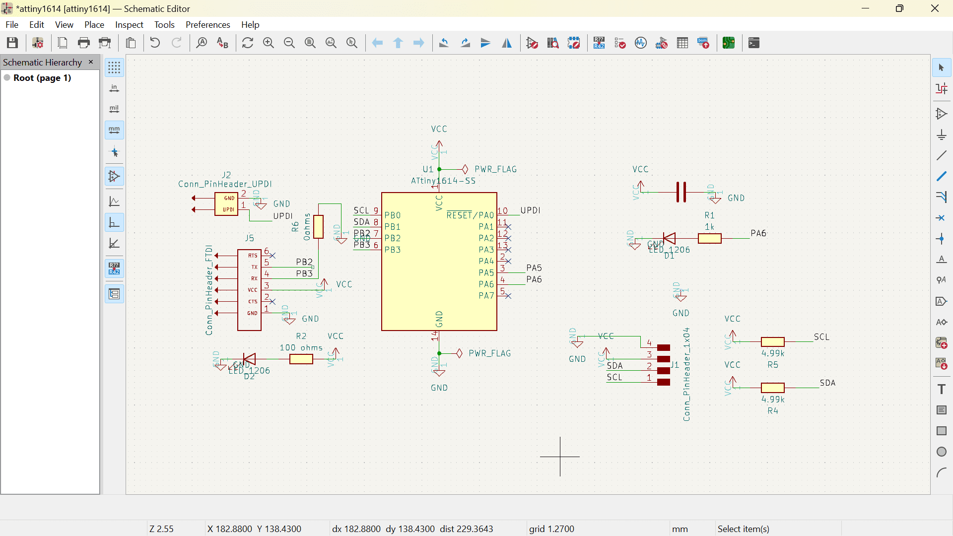
This is the final look of my schematic design.
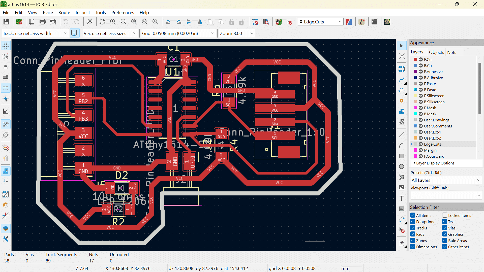
After running the ERC and having no errors, I updated the schematic to PCB and designed the board.
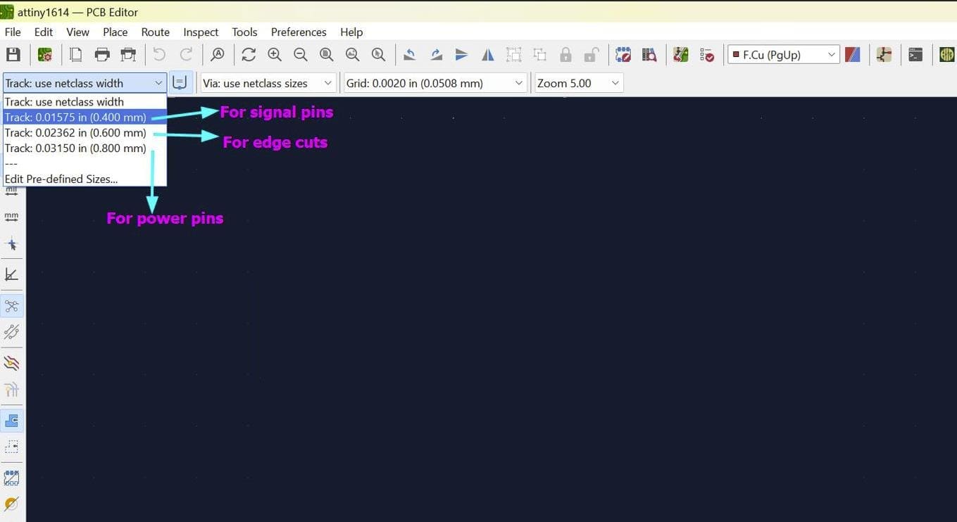
Like last week, I used 0.8 mm width for my power routes, 0.4 mm width for my signal routes and 0.6 mm for my edge cuts.
Here is my final PCB design
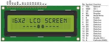
For this week, one of the output devices that I used is the LCD display so here are some few things I researched in this output device.
LCD (Liquid Crystal Display) is a type of flat panel display which uses liquid crystals in its primary form of operation. LEDs have a large and varying set of use cases for consumers and businesses, as they can be commonly found in smartphones, televisions, computer monitors and instrument panels.
Voltage Requirement: 4.7V - 5V
Current Requirement: 1mA (without backlight)
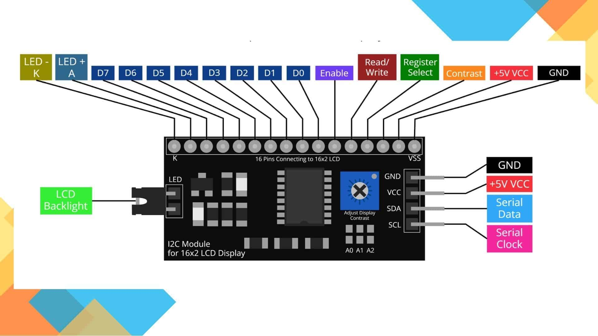
The I2C module allows us to connect several peripheral devices, such as sensors, displays, motor drivers, and so on, with only a few wires. Giving you lots of flexibility and speeding up your prototyping, without an abundancy of wires.
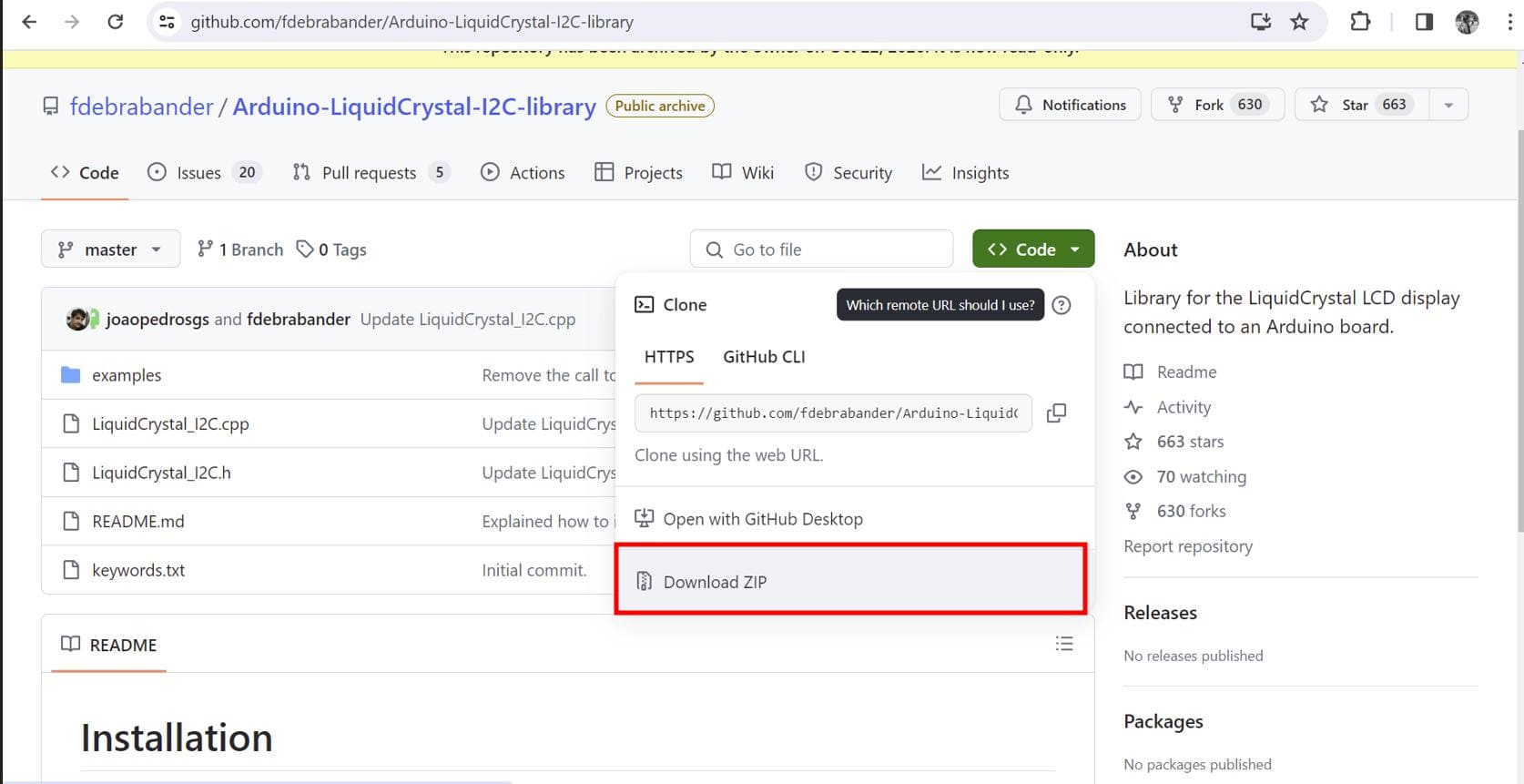
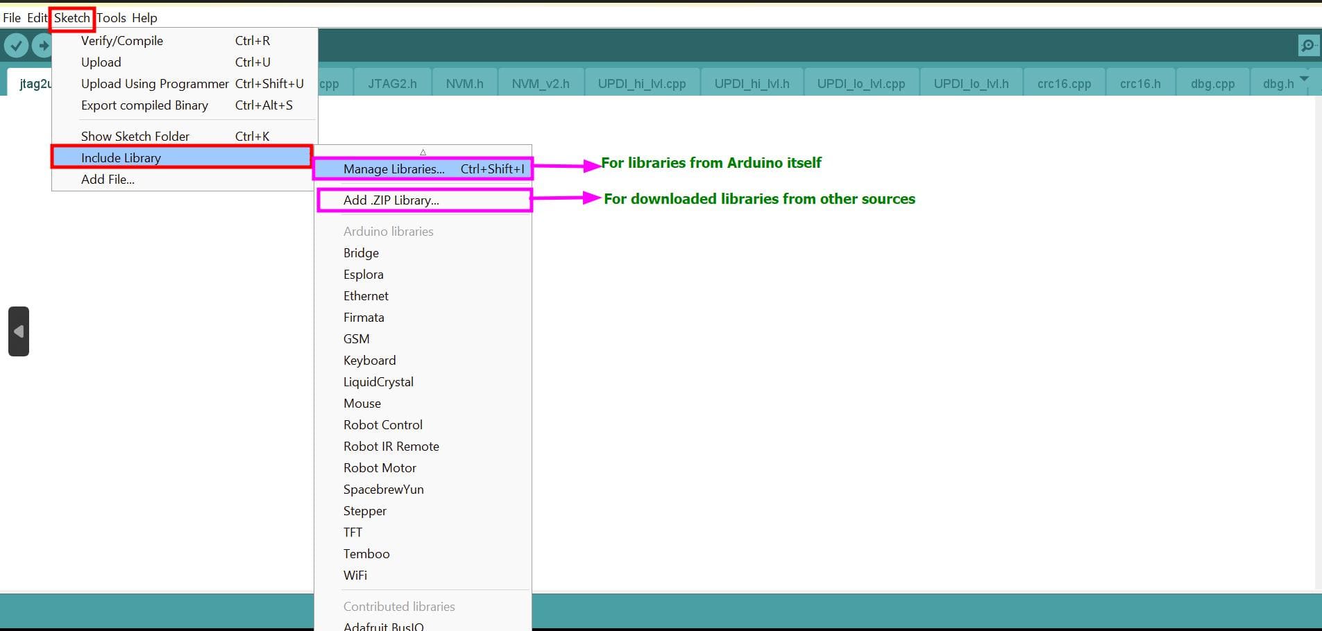
I had to download the library for LCD I2C which you can find here or the arduino software itself.
The Arduino IDE already have an inbuilt library for LCD, but without considering the I2C module. So I had to download the library for LCD I2C which you can find here or the arduino software itself.
If you are using the given library in the link, after downloading the library, it comes as a zipped folder so you can
select Add .ZIP Library
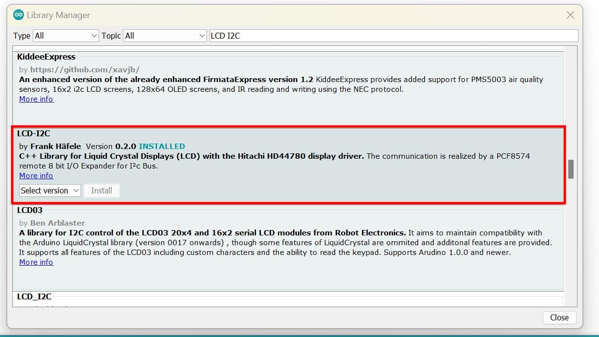
I downloaded the following library for my LCD
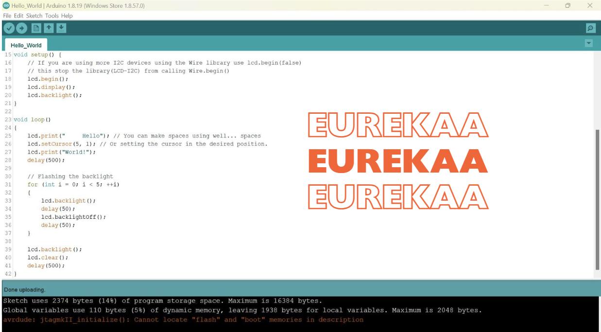
After having this library installed your software, go to files > examples and you will see that the library comes with attached examples. So I first chose the hello board example and it worked!!!
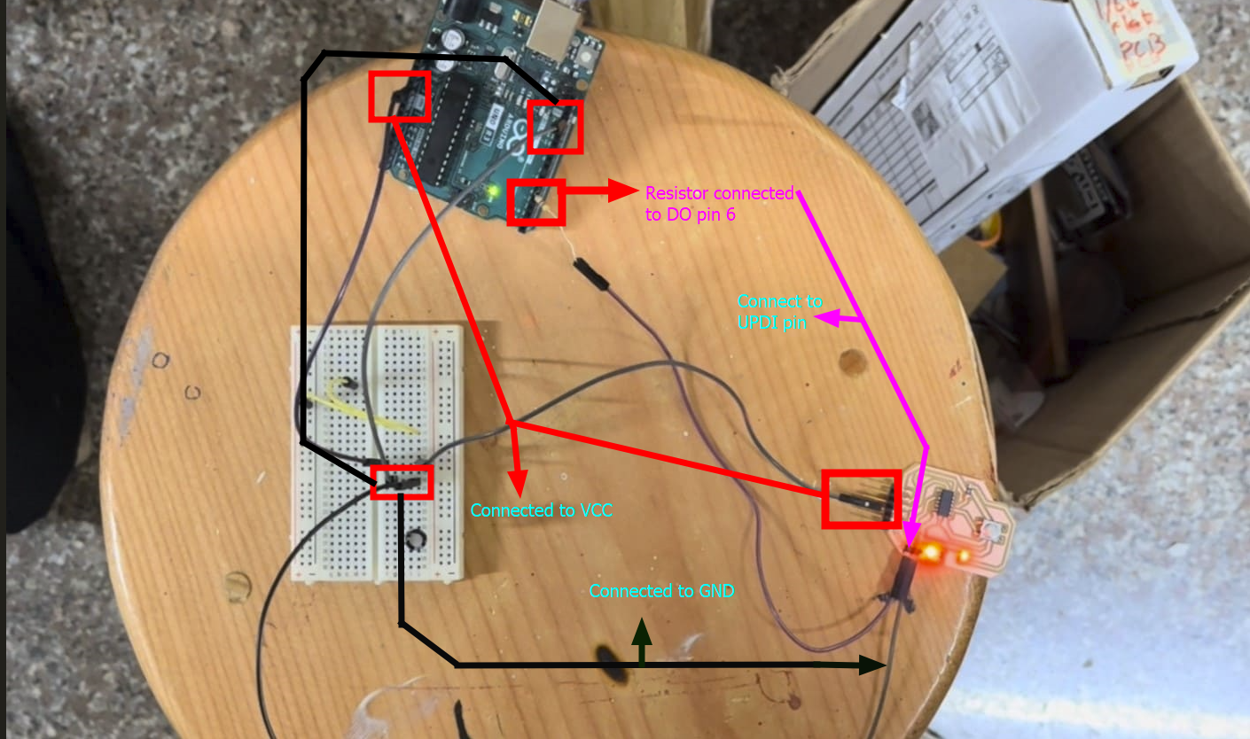
I am using the metro board as a programmer to upload code to my MCU board through jtagupdi which I explained in detail in week 8! It is also for power supply to my MCU board.
The connection is similar to the following image from my electronics design week but for this assginment I also connected the LCD display.
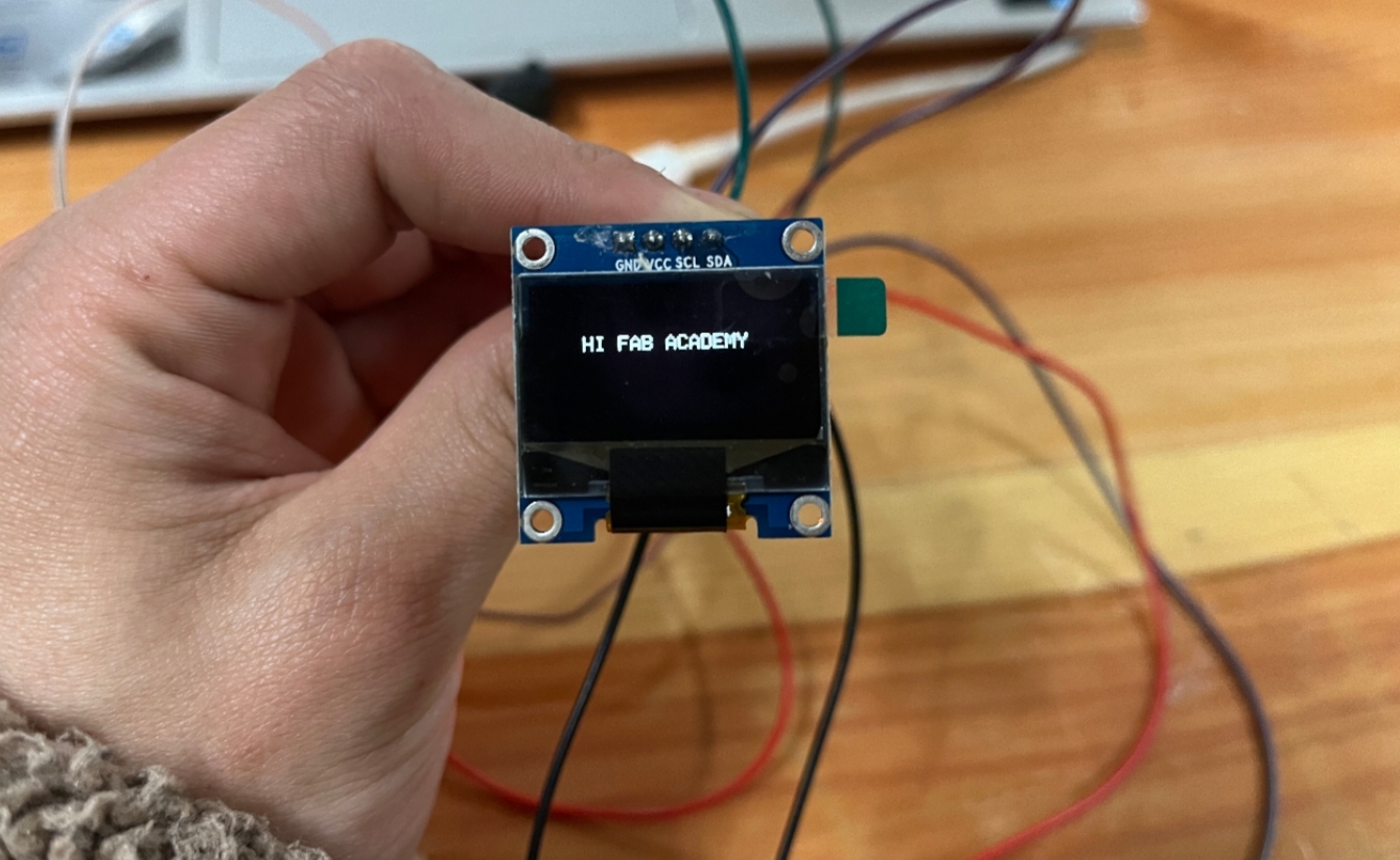
After the LCD worked, I got more motivated and tried the OLED which had more features.
An I2C OLED is an OLED (Organic Light-Emitting Diode) display that utilizes the I2C (Inter-Integrated Circuit) protocol for communication. This means it can be controlled and accessed using only two wires (SDA and SCL), making it a popular choice for projects involving microcontrollers or embedded systems where space and simplicity are important factors.
Voltage Requirement: 3.3V - 5V
Current Requirement: 20mA
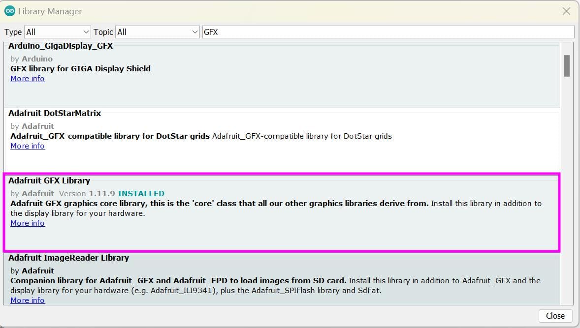
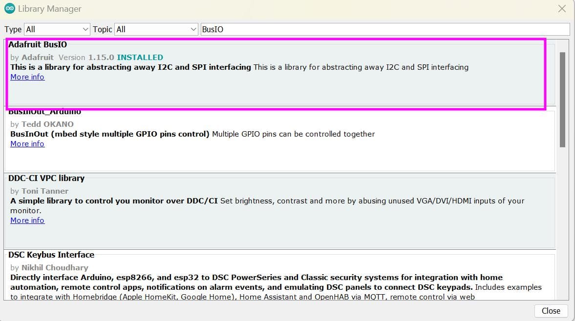
For OLED, we can find the commonly used library in the Arduino IDE software itself which can search up. Or you can find it on google. For that, the link is given here.
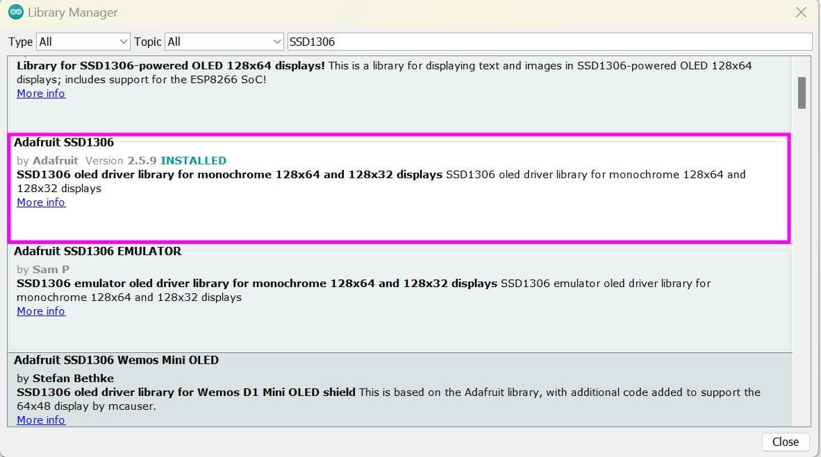
With this library, there are again two dependencies which is the Adafruit GFX Library and Adafruit BusIO
Similar to the LCD_I2C library this OLED library also had inbuilt examples and it worked!!!
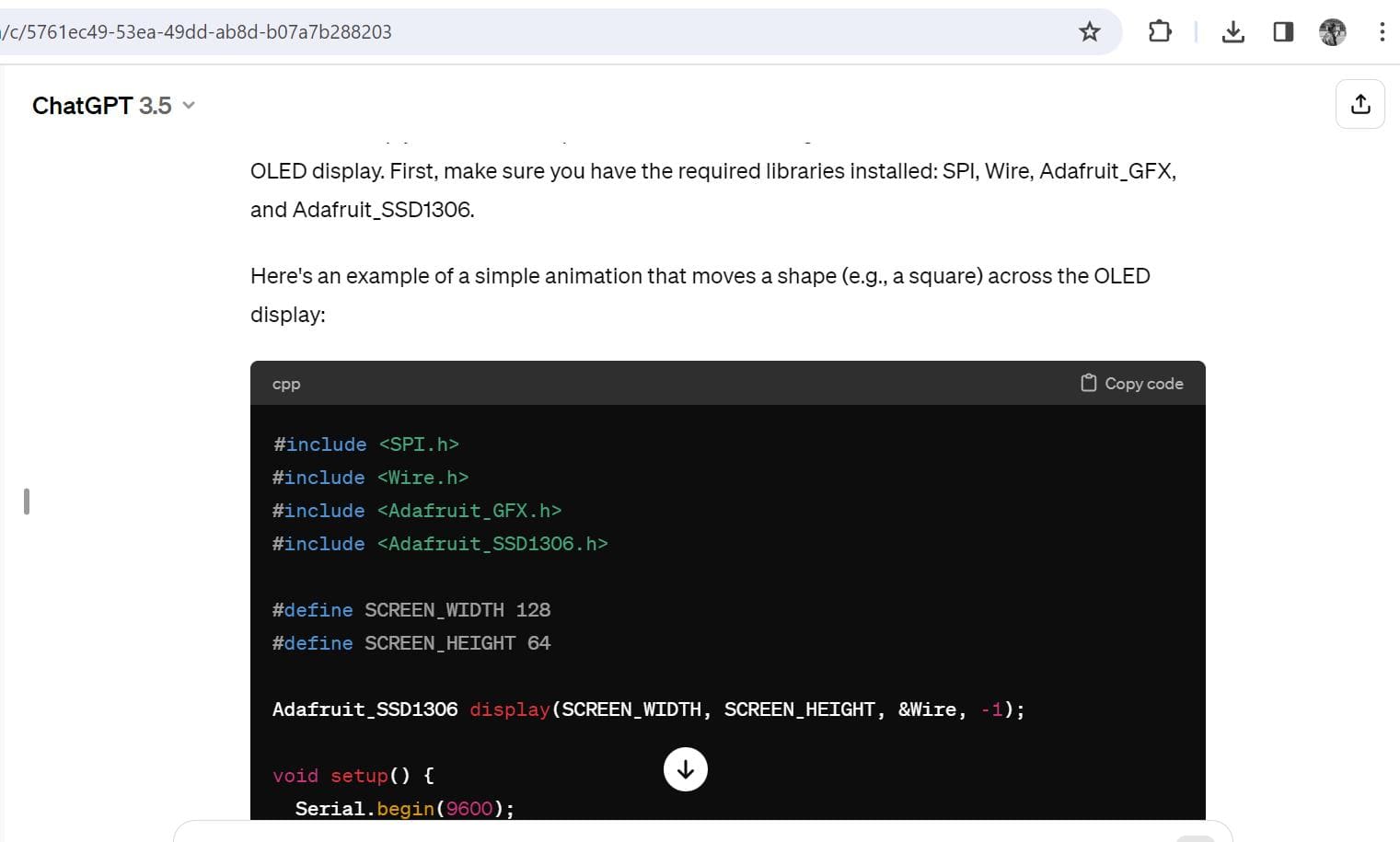
Next I generated some code for a simple animation from chatGPT with proper instructions and it did a great job!!!
Here is the prompt I gave:

Zipped Code Files
PCB Design Files