Mechanical Design, Machine Design
Mechanical Design (part 1 of 2)
Group assignment:
-
Design a machine that includes mechanism + actuation + automation + application
-
Build the mechanical parts and operate it manually Document the group project
Individual assignment:
- Document your individual contribution
Machine Design (part 2 of 2)
Group assignment:
-
Actuate and automate your machine
-
Document the group project
Individual assignment:
- Document your individual contribution
Learning outcomes
-
Work and communicate effectively as a team
-
Design, plan and build a machine
-
Analyse and solve technical problems
-
Recognise opportunities for improvements in the design
As usual here is my schedule

SO here is our poster and video:

3-d Scanner
So our group of 5 decided to make a 3-d scanner for this week’s assignment. We started off by making sketches for the design like this:

The general idea is a rotating platform (to place your object), and an arm that holds your scanner, and can move the scanner up and down for better results.
After confirming the idea, we decided to divide the work amongst ourselves:

Machine Building
Programming
Ngawang and I chose to take charge of the machine building’s programming portion (Andd it was quite fun and hard :] ). We tried to program the DC stepper motor to begin with and for this we took reference from this site
As we worked on programming the stepper motor using Tiny G board, we made sure to document the major processes and the following are some of the processes included in programming the Tiny G board!
So we will be using a stepper motor:

A Tiny G board:

A 24 volts battery:

To programme the Tiny G board, we decided to use UGS.
Why is the TinyG Necessary?
The TinyG is a crucial component in CNC (Computer Numerical Control) systems for controlling stepper motors. It ensures precise movement and control, which is essential for tasks like 3D scanning or machining where accuracy is key.
Why Can’t Stepper Motors Be Directly Hooked Up to an MCU?
Stepper motors require more complex control than servo or DC motors because of:
Complex Signals: Stepper motors need a series of electrical pulses to move. The frequency of these pulses controls the motor’s speed, and their sequence determines the direction. This requires precise timing, which a simple MCU (Microcontroller Unit) can’t manage alone.
Power Requirements: Stepper motors often need higher currents and voltages than an MCU can provide. Directly connecting a stepper motor to an MCU could damage it or provide insufficient power.
Microstepping: For smooth and precise movement, stepper motors use microstepping, which requires precise current control in the motor windings. An MCU can’t handle this on its own.
Synchronization: In applications like CNC, multiple stepper motors must move in perfect sync. Managing this level of coordination is too complex for a basic MCU without additional hardware like TinyG.
What Does the TinyG ACTUALLY Do?
The TinyG performs several key functions SUCH AS:
Pulse Generation: It generates the precise pulses needed to control the stepper motor’s speed and direction.
Current Control: It regulates the current to the stepper motor, enabling smooth and precise movement. Synchronization: It controls multiple stepper motors at once, ensuring they move together perfectly.
G-Code Interpretation: TinyG reads G-code commands (used in CNC machining) and translates them into motor movements.
Communication Interface: It allows communication between the CNC machine and the computer, enabling real-time adjustments.
1. Connecting Power and Motor
-
First, we verified and double-checked the correct wiring of our power input (black for ground, red or yellow for +24 volts).
-
Then we used a DC power supply between 12 and 30 volts capable of providing 4 to 15 amps.
-
After that we turned on the power supply and checked for correct voltage and polarity before connecting it to TinyG.

After connecting the power, we connected one pair of wires to the A1/A2 terminals and the other pair to the B1/B2 terminals on TinyG’s motor outputs.

Power Requirements for Stepper Motors
Stepper motors require a certain amount of power, which is a combination of voltage and current. We chose 24V for our stepper motor setup because:
Higher Speed and Torque: Higher voltage helps the motor move faster and with more power. This is important for making the motor spin quickly and handle heavier loads.
Stable Performance: Using 24V ensures the motor runs smoothly without getting stuck or overheating, which helps in maintaining reliable performance.
Compatibility with TinyG: The TinyG board works best with voltages between 12V and 30V. Using 24V keeps us within this range, ensuring the board operates efficiently.
Why Not Connect Directly to the MCU?
Unlike servo or DC motors, stepper motors require precise control of their movements. The TinyG controller provides this by sending specific signals to the motor. This ensures the motor moves the exact amount needed, which is crucial for tasks like 3D scanning.
2. Setting up Universal Gcode Sender
- Now, regarding the software, we decided to use the Universal Gcode Sender(UGS).
What Does Universal Gcode Sender (UGS) Do?
Universal Gcode Sender (UGS) is a software tool we used to control the TinyG board and the stepper motors.
Here’s why it’s important:
Gcode Interpretation: UGS reads Gcode, which is a set of instructions telling the motor how to move. It translates these commands into movements of the machine’s parts.
Real-time Control: UGS lets us control and monitor the motor’s movements in real-time, allowing for adjustments on the go.
User-Friendly Interface: The software is easy to use, with clear visuals and controls, making it simple to manage the motor’s operations.
Customizable Layout: UGS allows us to customize the interface, making it easier to work with for our specific needs.
Advanced Features: It includes advanced tools like 3D visualization, helping us see the motor’s movements and ensure everything is working correctly.
By using UGS, we could control the stepper motors accurately, making our 3D scanner project successful.
We started by downloading and installing the Universal Gcode Sender, a terminal emulator through this site
- Then go to the downloaded folder and then open this file

- We selected the port

- And connected to TinyG.

The content inside the green box indicates a successful connection. Then we identified the coil pairs of our stepper motor using a volt meter.
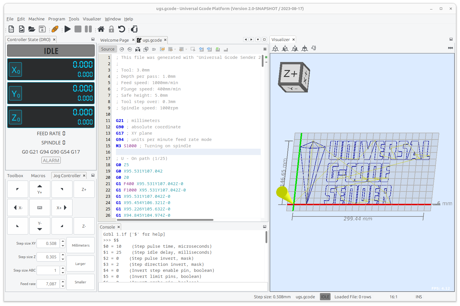
This is how the UGS Platform main window should look like:

UGS also has it’s own Customizable panel layout:

After setting the UGS platform, we moved on to seting the current of our board and power supply!!
4. Setting Motor Current
- Then using the trimpots near each axis, we adjusted the motor current.

We started with the current at zero and gradually increase it until the motor moved smoothly without stalling or running too hot.
Note: Avoid overdriving the motors, which can lead to overheating and damage.
5. Test Drive
-
Once everything is connected and configured, test drive your stepper motor by sending movement commands through TinyG.
-
Check for smooth operation, correct direction, and appropriate speed.
For the test drive, we tried with the code that was given in the reference documentation.
We uploaded this code g1 f400 x100 :
In the above G-Code,
-
G1: This is a standard G-code command that instructs the machine to move in a straight line from its current position to a specified point at a specified feed rate. -
F400: This part of the command sets the feed rate or the speed at which the machine should move. The value 400 indicates a feed rate of 400 units per minute. This determines how fast the motor will spin. -
X100: This part of the command specifies the target position along the X-axis where the machine should move to. In this case, it’s instructing the machine to move to the X-coordinate of 100 units.
It worked!!
After successfully spinning the motor, we made the gears after measuring the widths and legths of the motor head and it turned out like this:


Designing the gear
The gears were crucial for moving the rotating platform and the scanning arm. We firstly, sketched the basic layout, including the gears. The gears were needed to ensure smooth and precise movement.
To decide the number of teeth reuired, we calculated the number of teeth based on the torque and speed ratio. This involved a lot of math and trial and error to get it right.
Understanding Gear Ratios
A gear ratio is the ratio between the number of teeth on two meshing gears. It determines how the rotational speed and force are transmitted from one gear to another. The formula for the gear ratio (GR) is:
Gear ratio (GR) = Number of teeth on driven gear / Number of teeth on driving gear. This means the driven gear will rotate once for every three rotations of the driving gear. This setup increases the torque available to rotate the platform, which is crucial for handling heavier objects.
Why This Matters?
By carefully selecting our gear ratios, we could ensure that the motor had enough power to rotate the platform smoothly and accurately. This was important for achieving high-quality scans without any jerky movements.
For this we used an online gear maker from this website!!
After that, we used laser cutter to fabricate our gear and we used cardbox as the material for the gear so that we could reduce the weight on the motor.
Now that we had the gear, we moved on to integrating the motor and the gear together. And we were able to make it run… After that we decided to add more weight on the gear base and we were successfully able to make it spin it!!
AND IT WORKED!!
Since now we had the basic idea of how to control the stepper motor, we started working on the other motor!
Project Plan!
For our scanning machine, we are trying to control 2 motors in which the first motor will be used to rotate the platform and the second second motor which will be kept side-down to move the scanning platform of the object vertically.
To control the 2 motors we tried several relevant codes which obviously didn’t work in the first iteration but after several tries, the following code worked!!

To verify if the code worked or not, scroll to the bottom of the page to view our group video!
Since the programming part was almost over, we decided to work on the arm designs. For the arm, we used cnc to cut the first prototype and here is a picture of the 3 after trying to assemble it!! (PS: this was done before we were done with the programming part… View our project video at the end to see the progress!!)

The wooden arm that we printed didnt come out that good so we decied to 3D print the arm so that it can be smoother.

As we assembled the parts, we realised that the arm mechanism was not working well so we moved on to a pulley system and redesigned the parts. Since we had limited time, all of us started work on the designs and here is us trying to assemble our new design!!

Jumpscare!!!!

After assembling our machine, we worked on our documentations and making the video!!
Click here to view the group video!
Design Strategies and Approaches
We(Pemo and I) started by sketching our design ideas, settling on a rotating platform for the object and an arm that could move the scanner vertically. We chose to use stepper motors because they offer precise control, which is essential for accurate scanning. For programming, we used UGS and the details for it is mentioned above.
For the mechanical parts, we used a laser cutter to create the base and arm components. The laser cutter allowed us to achieve precise cuts and assemble the parts quickly. Initially, we made the arm from wood, but it proved to be unstable. This instability affected the accuracy of our scans, so we decided to redesign the arm using 3D printing. The 3D-printed arm provided better stability and smoother movement.
Challenges and Solutions
We faced several challenges during the project. The first challenge was the instability of the wooden arm. It wobbled and didn’t move smoothly, which affected our scanning results. To solve this, we switched to a 3D-printed arm, which was more stable and provided smoother movement.
Another major challenge was programming the stepper motors using the TinyG board. Initially, the motors stalled and ran inconsistently. We resolved this by carefully adjusting the motor current using the trimpots on the TinyG board and refining our G-code commands to ensure smooth operation.
Integrating the TinyG board with the Universal Gcode Sender (UGS) software was also tricky. Our initial attempts to connect and control the motors failed due to incorrect wiring and software settings. Through trial and error, and by following the TinyG documentation closely, we managed to correct the wiring and configure the UGS software properly, leading to successful motor control.
Additionally, coordinating tasks and maintaining consistent progress as a team was challenging. We used a shared project timeline and held regular meetings to keep everyone updated and address any issues promptly. This approach helped us stay organized and work efficiently.
Reflection
This week, our group of five decided to build a 3D scanner for our project. The design included a rotating platform to hold the object and an arm that moves the scanner up and down for better scanning. We divided tasks among ourselves, and I focused on programming the stepper motors using a TinyG board. We used software called Universal Gcode Sender (UGS) to control the motors, making sure they moved smoothly without overheating. After successfully programming the motors, we designed and assembled the mechanical parts, switching from a wooden arm to a 3D-printed one for better reliability. Throughout the week, we faced several challenges but learned a lot about working together, communicating clearly, and dividing tasks efficiently. We also improved our problem-solving skills by debugging and fixing issues with the programming. Overall, this week was tough but rewarding, boosting our confidence for future projects and teaching us valuable teamwork and technical skills.
Files
Phew!!! Finally machine designing week is over!!!
THAT’S IT FOR THIS WEEK!!!
HAVE A GOOD DAY!