11. Input Devices
Group assignment:
-
Probe an input device(s)’s analog levels and digital signals
-
Document your work on the group work page and reflect on your individual page what you learned
Individual assignment:
- Measure something: add a sensor to a microcontroller board that you have designed and read it.
Download Design Files
Click here to download my design files folder
Group Work Reflection
The group work required us to probe an input device’s analog levels and digital signals and, thus, use one of the group members input devices to do these probings on. From the group work I think I learned most of how important it is to understand what a sensor does to be able to understand what probing/oscilloscope values mean in relation to the sensor. Because we used Landon’s input device’s sensor (the one that was working the soonest), I had to brush up on the details of the sensor before I could begin to draw conclusions about what the readings meant.
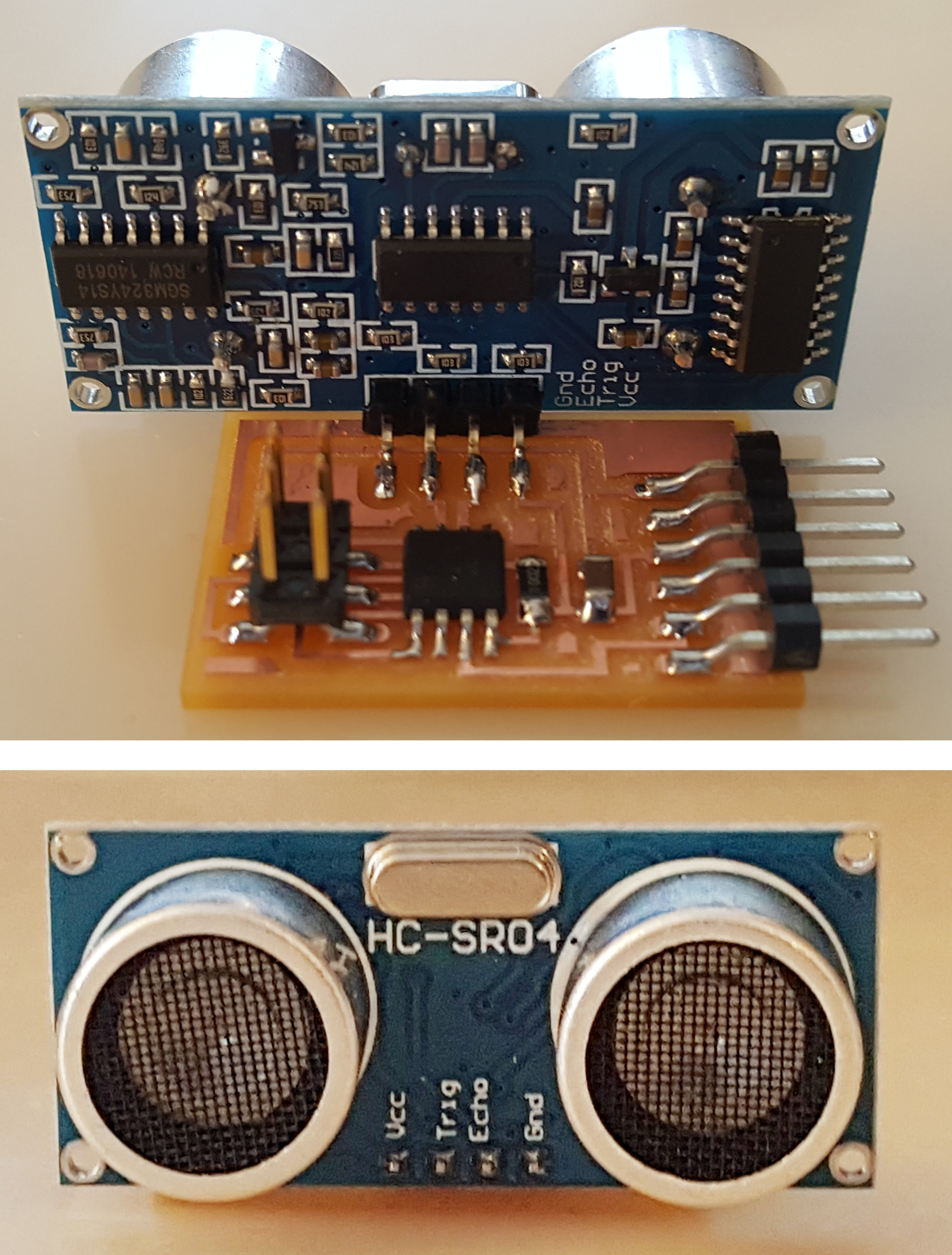
Sonar Sensor
According to Circuit Bread, a “sonar sensor emits a sonic signal that will be reflected back when it encounters an obstacle (object) and then calculates the object’s distance and position based on the reflection time and wave pattern.”
When deciding what sensor I wanted to use, I first looked into other Fab Academy student’s work. I ended up deciding on doing a sonar distance sensor after viewing Alberto Porri’s 2021 Fab Academy Inputs documentation. After identifying the pictured chip on Alberto Porri’s PCB as a ATTiny45-10SU and ensuring we had it in the lab, I decidied to procede following Neil and Alberto Porri’s documentation of using a sonar sensor.
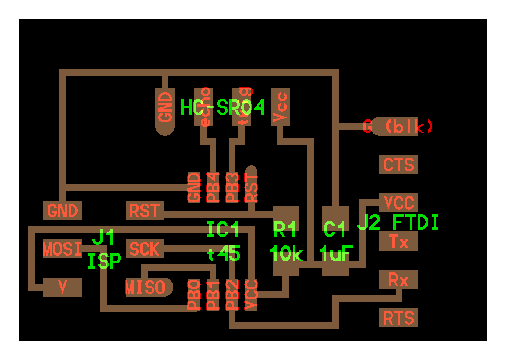
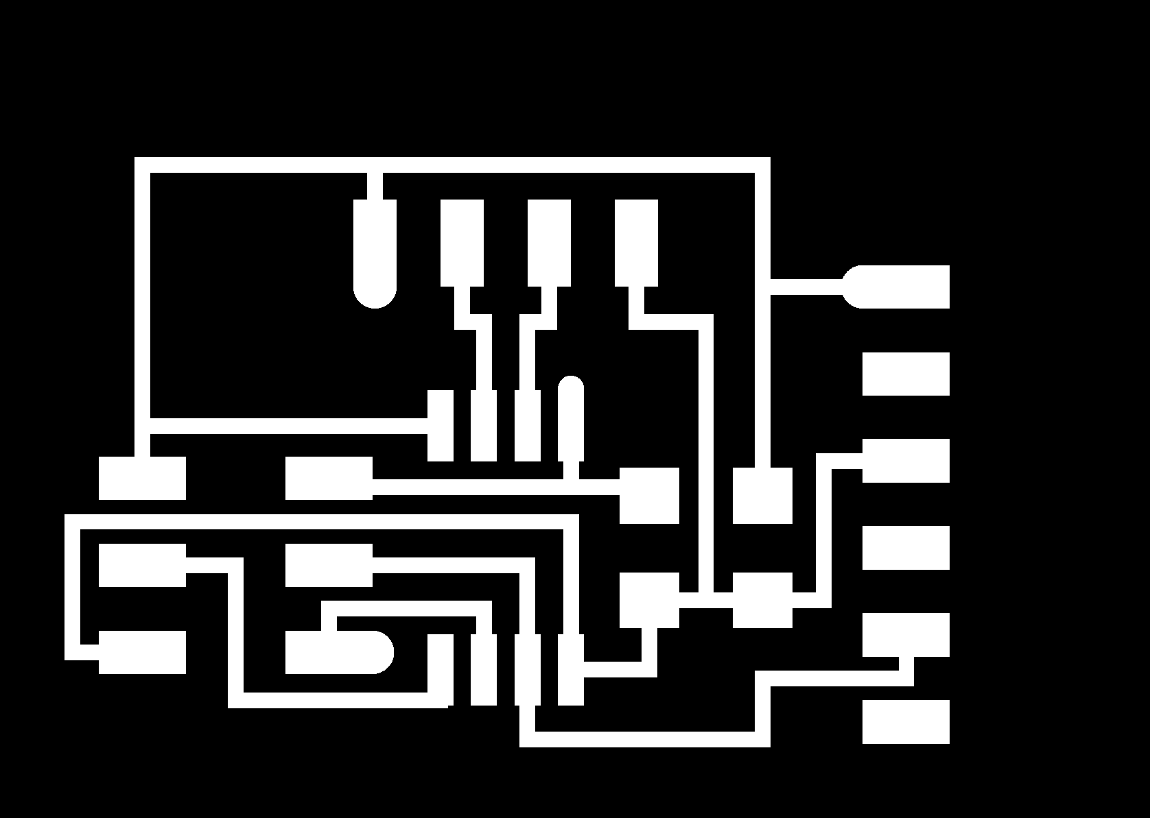
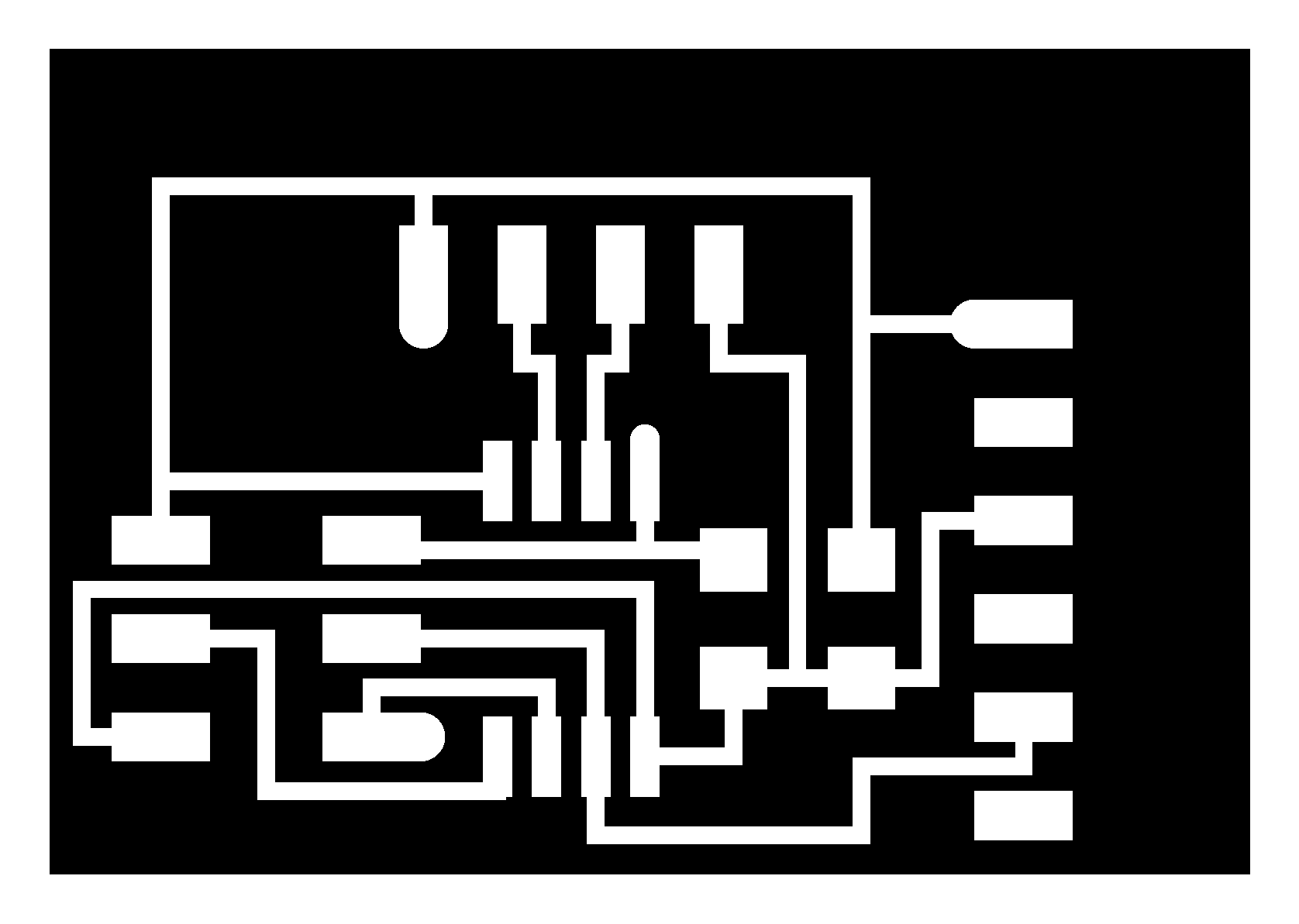
I milled this board from Alberto Porri’s site.

I then soldered the components on:

I was then reviewing this How to Mechatronics: Ultrasonic Sensor HC-SR04 and Arduino – Complete Guide article to help with pinouts from the sonar to an arduino.
At this point Mr. Dubick saw what I was doing and mentioned that Neil talked about how the sonar was out of date and to avoid using it. I had forgotten this and decided to pivot to a more practical and worthwhile use of time.
Time of Flight Sensor
According to SeeedStudio, Time of Flight “is the measurement of the time taken by an object, particle, or wave to travel a distance.”
Planning
Originally I planned to use a limit switch button as an input on my final project. For the individual portion of inputs week, however, it specificed that we needed to “add a sensor to a microcontroller board that you have designed and read it,” thus, the limit switch being a button and not a sensor, I figured I would complete this week with an easy sensor and then focus on programming the limit switch.
After talking to Mr. Dubick, however, he suggested I use a time of flight sensor in my final project as an input. The goal of the input I will use in my final project is to tell when a medicine cabinet’s door is open.
I remembered seeing that Adam Stone had used a time of flight sensor in his week 11 input devices documentation. After scrolling through his work, I decided a time of flight sensor would be a viable option for my final project and would be a good learning experience for myself. I decided to use the Adafruit VL53L1X Time-Of-Flight sensor.
I also read through this Instructables article relating to time of flight sensors.
Previous Experience
Furthermore, I realized I had used a time of flight sensor over the summer while doing research with the CURIE program at Cornell University:

I have more about this on my linkedin.
PCB
Following a similar design to Adam’s, I made the following PCB in KiCad:
Schematic:

PCB:

milled PCB:

I then soldered an seeed XIAO RP2040 and a 1x5 Conn Header on the board:

The time of flight sensor came with a 6 pin male header that needed to be soldered on before I could connect it to the PCB/start programming it.


I then connected the time of flight sensor to the PCB:

Specs: Libraries, Boards, etc.
-
The library I used was “VL53L1X” by Pololu
-
I programmed the ToF (Time of Flight) on Arduino IDE 2.2.1
-
The board I used was “Seeed XIAO RP2040”
Additional settings I used but am not sure if were important that I specifically used include:
-
USB Stack: “Adafruit TinyUSB”
-
Upload Method: “Default (UF2)”
Programming
Code
An adaption of Adam Stone’s adaption of Adrian Torres’ code to work for my Time of Flight Sensor is below:
#include <Wire.h>
#include "VL53L1X.h"

VL53L1X sensor;

void setup()
{
Serial.begin(115200);
Wire.begin();
Wire.setClock(400000); // use 400 kHz I2C

sensor.setTimeout(500);
if (!sensor.init())
{
    Serial.println("Failed to detect and initialize sensor!");
    while (1);
}

// Use long distance mode and allow up to 50000 us (50 ms) for a measurement.
// You can change these settings to adjust the performance of the sensor, but
// the minimum timing budget is 20 ms for short distance mode and 33 ms for
// medium and long distance modes. See the VL53L1X datasheet for more
// information on range and timing limits.
sensor.setDistanceMode(VL53L1X::Long);
sensor.setMeasurementTimingBudget(50000);

// Start continuous readings at a rate of one measurement every 50 ms (the
// inter-measurement period). This period should be at least as long as the
// timing budget.
sensor.startContinuous(50);
}

void loop()
{
Serial.print(sensor.read());
if (sensor.timeoutOccurred()) { Serial.print(" TIMEOUT"); }

Serial.println();
}
Adam recommended following the following steps, however, I’m not sure all of them were actually necessary in the success of my programming of the sensor. I decided to follow them, nonetheless, to avoid any additional errors in the process with the limited time I had:
-
plug in without bootloader button
-
select board + board
-
upload (it will fail)
-
unplug
-
plug in while holding bootloader button
-
select UF2 Board as the upload port
-
upload
-
select the new port which will be COM something
-
open the serial monitor (if applicable)
PCB attempt 1
When I first tried programming the ToF sensor, I started by using my PCB board and following the steps Adam mentioned (as detailed above). Both the XIAO RP2040 on the PCB board and the ToF sensor indicated they were receiving power, however, I was having some trouble getting it to work.

I first tried just uploading the code above with no special steps… I then realized I forgot to install the library (o_o oops). I then downloaded “VL53L1X” by Pololu (not “Adafruit VL53L1X” by Adafruit).
I then uploaded the code again; it didn’t fail but it also didn’t work.
I then unplugged the board and plugged it in again while holding down the bootloader button on the RP2040. I got the error message “Failed uploading: uploading error: exit status 1.”
I then selected “UF2 Board” as the port under the tools tab and uploaded the code again. I got the error message “No monitor available for the port protocol uf2conv. Could not connect to UF2_Board uf2conv port.”
“INFO_UF2” opened from the Notepad application. I was very confused.

I then tried uploading the code again and this time, although I still got the “No monitor available…” error as before, the PC’s Settings indicated that it was “Setting up a device: We’re setting up ‘XIAO RP2040.’” Furthermore, in Arduino IDE’s output, it said:
“Converting to uf2, output size: 156672, start address: 0x2000
Scanning for RP2040 devices
Flashing D: (RPI-RP2)”
which seemed like a positive sign to me!
I tried opening the serial monitor again but it still wasn’t doing anything.
![]()
I then uploaded the code again, this time with the line:
“Wrote 156672 bytes to D:/NEW.UF2”
appearing in addition to the previous outputs and a folder labeled “RPI-RP2 (D:)” opening and showing files “INDEX,” “INFO_UF2,” and “NEW.UF2” in it.

It sucessfuly uploaded but still wasn’t working. So, I decide to pivot:
XIAO RP2040 directly to ToF Sensor
I started back at square one with a breadboard and XIAO RP2040.

I uploaded the code and this time, it worked!

Although I was elated at first, I then realized that the values recorded were not changing because of any physical/environmental changes in the sensors range, but rather just staying between 1.09 and 1.11.
I then ditched the breadboard entirely and just took female to female wires from the RP2040 to the ToF sensor.

The sensor still recorded values, however, it still only recorded values between about 1.09 to 1.11, regardless of if my hand or any other object was moving substantially closer or further away.

I then thought that maybe the way I had soldered the 1x6 header onto the ToF sensor was messing it up (I thought that the light could be reflecting off of the black bases to the wires I was putting on the header and thus making the recording such small, consistent values). I first tried to solder-sucker the header off, but, to no avail, I grabbed another ToF sensor and soldered the header on the other way this time.

I connected the sensor to the RP2040, uploaded the code, and no change. It still was recording values between 1.09 and 1.11 only.
I wasn’t sure what could possibly be the problem, so I decided to pivot again and switch up the equipment I was using.
PCB attempt 2
I grabbed the PCB board I tried to use earlier and went back, inspected, and improved my soldering job on the RP2040 as I thought that might have been the problem previously.

I then connected the sensor to the board, plugged it in, switched my port to the one it was now connected to (it was COM and some number between 37 and 42, basically the only other port besides COM1, the notoriously temperamental beast of a port). Then, IT WORKED!
Reflection
This week was extremely refreshing for me. I encountered challenges and, in a timely manner for once, pivoted and overcame them. A few days prior to completing this week’s assignment, I had learned that I was trying to program for output devices week with an Arduino Uno AND a LCD that were BOTH broken. I had been so very confused and doubtful of myself before I had this realization and had automatically assumed that I was the problem. I felt so hopeless because I couldn’t get a HELLO WORLD code, an EXAMPLE code, to work WITH AN ARDUINO! I was seriously doubting how I would ever get through fab academy if I couldn’t even use an Arduino. And to put icing on the cake, my Macbook doesn’t like to program anything and my house in an apple/mac household with no other brand of laptops or computers so I was limited to the time I had access to the lab and its computers to be able to try and get a HELLO WORLD CODE TO WORK WITH AN ARDUINO. Talk about embarrassing when surrounded by fellow fab students who are insane at coding and others who knew nothing about it before fab academy and yet are excelling at it and you can’t even get an example code to upload with an arduino. So, learning that I actually wasn’t the problem and could potentially not be extremely atrocious at programming was so amazing (when I tell my stress levels decreased so much after this realization I mean it – happy fab happy life fr). So, TEST YOUR EQUIPMENT!!!
References
http://fab.cba.mit.edu/classes/863.10/people/matt.blackshaw/week8.html
https://www.digikey.com/en/products/detail/microchip-technology/ATTINY45V-10SU/735468
http://academy.cba.mit.edu/classes/input_devices/sonar/hello.HC-SR04.jpg
http://academy.cba.mit.edu/classes/input_devices/sonar/hello.HC-SR04
http://academy.cba.mit.edu/classes/input_devices/sonar/hello.HC-SR04.png
http://academy.cba.mit.edu/classes/input_devices/sonar/hello.HC-SR04.jpg
http://academy.cba.mit.edu/classes/input_devices/sonar/hello.HC-SR04.traces.png
http://academy.cba.mit.edu/classes/input_devices/sonar/hello.HC-SR04.traces_exterior.png
http://academy.cba.mit.edu/classes/input_devices/sonar/hello.HC-SR04.interior.png
http://academy.cba.mit.edu/classes/input_devices/sonar/hello.HC-SR04.c
http://academy.cba.mit.edu/classes/input_devices/sonar/hello.HC-SR04.make
http://academy.cba.mit.edu/classes/input_devices/sonar/hello.HC-SR04.mp4
https://pub.fabcloud.io/tutorials/week04_electronic_production/mods.html
https://www.google.com/search?client=safari&rls=en&q=mapping+with+sensors&ie=UTF-8&oe=UTF-8
http://fabacademy.org/2020/labs/leon/students/adrian-torres/fabxiao.html#inputs
https://www.instructables.com/Time-of-Flight-Sensor-Alerter/