Week13. Output Devices
Group assignment:
Measure the power consumption of an output device. Document your work on the group work page and reflect on your individual page what you learned.
Individual assignment:
Add an output device to a microcontroller board you’ve designed and program it to do something.
Group assignment can be viewed at this link. - week13 Group assignment
Group assignment:
What I learned this week: 1. What is an output device? 2. The relationship between output devices and microcontrollers? 3. How I determined power consumption of an output device.
1. What is an output device?
An output device is a part of computer hardware that transfers information or data to people or other devices. These devices are capable of converting computer-processed data into a human-understandable form, such as vision or auditory signals, or are capable of controlling machines to perform physical movements.
2. The relationship between output devices and microcontrollers?
Output devices are a key link in user interaction with computer systems. They enable people to understand and utilize the results of computer programs and data processing. Of course, these output devices also require appropriate hardware drivers or software to control their behavior. For example, a microcontroller is one of the hardware that can drive them. For this personal project, I plan to use a microcontroller to control an OLED screen to display text. The principle is as shown in the picture I drew:
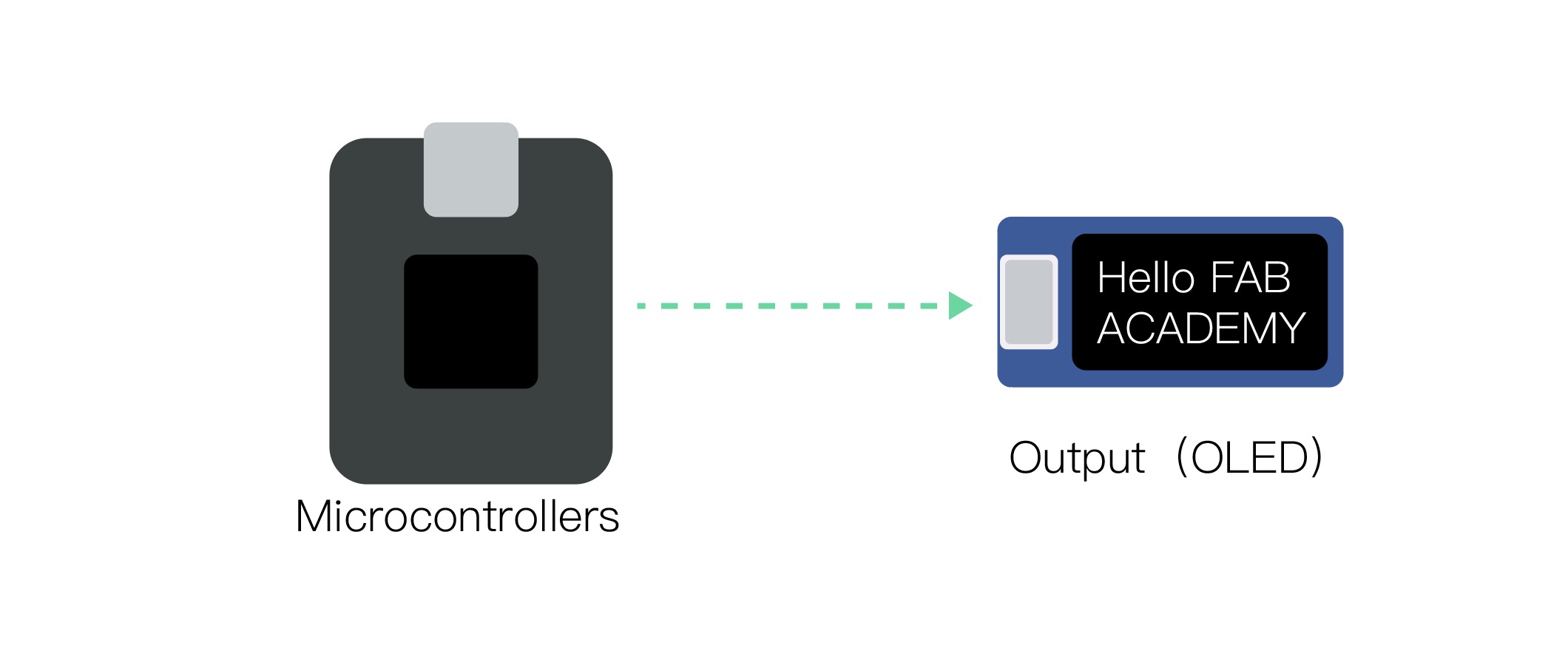](../../images/week13/week13_01.jpg)
3. How I determined power consumption of an output device.
The following is what I took during the program testing phase, the process of testing the circuit.
First I need to know the formula for calculating power which is:
[ P = VI ]
( P ) is power, measured in watts (W).
( V ) is voltage, measured in volts (V).
(I) is the current in amperes (A).
At this time we need to use our multimeter, this is the multimeter in our laboratory:
 The arrows above indicate some knowledge points that will be used this time.
First, let’s measure the current. The method is to first turn the multimeter’s knob to the “mA” position. The black interface clamps the GND and the red interface clamps the 3.3V output. Then we can read the data: 45.09mA.
It should be noted here that the current unit we measured is mA, so it needs to be converted into A before it can be entered into the formula, 45.09mA=0.04509A

Then let’s measure the voltage. Turn the knob to the “V” position, clamp the black connector to GND, and the red connector to the 3.3V output. We can see that the reading is: 3.25V

then I got (I)&(V), base on the formul, we can have: P=VI=0.04509A x 3.25V= 0.147W
In other words, my OLED screen requires 0.147W of power
Individual assignment:
This week’s homework is to make an output device. I’m going to use OLED to make a project to display text.
1. Schematic
Here I used XIAO ESP32 C3 and an Grove OLED sensor to build the project.


2. PCB design
then I got the PCB board like this,and Check design rules, perfect! then I can export the gerber file
 convert Gerber to PNG
 convert PNG to Gcode

3. Milling the PCB board
The manufacturing steps are explained in detail in week8, so I won’t go into details here.
then I got my input board:


Here is the kicad file:
week13_output_kicad
Here is the Gcode file:
top_layer_outline_1000dpi (2).png (1).nc>
top_layer_traces_1000dpi (2).png (3).nc>
4. Programming
This code is an Arduino sample program that initializes the display on the Grove OLED display via I2C communication and outputs some text and graphics.
and the program will also consist of two main parts: setup() and loop().
Before talking about the main program, let’s take a look at what libraries need to be installed in this program.
#include <Wire.h> // Arduino的I2C通信库
#include <Adafruit_GFX.h> // Adafruit的图形库
#include <Adafruit_SSD1306.h> // Adafruit的SSD1306 OLED驱动库
These three libraries are used to implement I2C communication, provide basic graphics functions, and SSD1306 OLED-specific operation and display control.
- Define OLED display parameters:
#define SCREEN_WIDTH 128 // 屏幕宽度,以像素为单位
#define SCREEN_HEIGHT 64 // 屏幕高度,以像素为单位
#define OLED_RESET -1 // OLED重置引脚,设置为-1表示没有使用
This code defines the width and height of the OLED screen (in pixel units), as well as the setting of the reset pin (OLED reset pin, set to -1 to indicate not used).
- Initialization screen:
void setup() {
  if(!display.begin(SSD1306_SWITCHCAPVCC, 0x3C)) {
    for(;;);
  }
  // 其他初始化代码...
}
In the setup() function, the OLED screen is first initialized. If display.begin() fails to initialize, it will enter an infinite loop (indicating a program error and cannot continue).
- Clear the screen and set the text:
display.clearDisplay();
display.setTextSize(1);
display.setTextColor(SSD1306_WHITE);
display.setCursor(0,0);
display.println(F("Hello, Grove OLED!"));
This part of the code clears the screen, then sets the text size to 1, the text color to white, and starts displaying “Hello, Grove OLED!” in the upper left corner of the screen (coordinates 0,0).
- Empty loop function:
void loop() {
  // 这里可以放置代码来更新显示内容或其他循环操作
}
The loop of this sample code is empty. I am going to add a piece of code to this loop below to test the effect.
The sample code is as follows:
/* 在这个例子中,我们只在setup()里面显示内容,
   loop()可以用来更新显示内容或者做其他事情。 */

#include <Wire.h>
#include <Adafruit_GFX.h>
#include <Adafruit_SSD1306.h>

// OLED display width, in pixels
#define SCREEN_WIDTH 128
// OLED display height, in pixels
#define SCREEN_HEIGHT 64
// I2C地址(装配在 Grove OLED 模块背后)
#define OLED_RESET    -1 // 如果没有重置引脚则设置为 -1
Adafruit_SSD1306 display(SCREEN_WIDTH, SCREEN_HEIGHT, &Wire, OLED_RESET);

void setup() {
  // 初始化OLED显示屏。
  if(!display.begin(SSD1306_SWITCHCAPVCC, 0x3C)) {
    // 如果初始化失败,进行无限循环。
    for(;;);
  }

  display.clearDisplay(); // 清空显示内容。

  // 设置文本大小、颜色、光标位置然后输出文本。
  display.setTextSize(1);
  display.setTextColor(SSD1306_WHITE);
  display.setCursor(0,0);
  display.println(F("Hello, Grove OLED!"));

  // 在显示器上绘制一条线。
  display.drawLine(0, 10, SCREEN_WIDTH, 10, SSD1306_WHITE);

  // 显示前面设置的内容。
  display.display();
  delay(5000); // 暂停5秒。
}

void loop() {
  // 这里可以放置代码来更新显示内容或其他循环操作
}

After the program is burned, the effect is as follows:
Code modification 01
After learning the meaning of the entire code, I made some small modifications to this code, as follows
  display.setTextSize(3);
  display.setTextColor(SSD1306_WHITE);
  display.setCursor(0,0);
  display.println(F("Hello, FAB ACADEMY!"));
Here I changed the font size to size 3, and changed the text to “Hello, FAB ACADEMY”
I also removed the straight line, which is:
display.drawLine(0, 10, SCREEN_WIDTH, 10, SSD1306_WHITE);
After burning, the effect is like this:

The size 3 fonts were still too big, and when I saw the characters on the display skipping lines, I changed them to size 2, which looked much more comfortable, and also this is the hero shot:

Code modification 02
I mentioned earlier that I need to add a piece of code to the loop to make it run. Here is the code I added:
void loop() {
  static const char letters[] = {'K', 'A', 'W', 'I'}; // 字母数组
  static int index = 0; // 当前显示字母的索引
  static unsigned long lastUpdate = 0; // 上次更新屏幕的时间
  unsigned long currentMillis = millis(); // 当前时间

  // 每隔3秒更新一次屏幕
  if (currentMillis - lastUpdate >= 3000) {
    // 更新时间
    lastUpdate = currentMillis;

    // 清除屏幕内容
    display.clearDisplay();

    // 设置显示字母的位置和样式
    display.setTextSize(2);       // 设置文本大小
    display.setTextColor(WHITE);  // 设置文本颜色
    // 将文本居中显示
    display.setCursor((SCREEN_WIDTH - 12) / 2, (SCREEN_HEIGHT - 16) / 2);

    // 显示字母
    display.print(letters[index]);

    // 显示缓冲区的内容
    display.display();

    // 移动到下一个字母的索引
    index = (index + 1) % sizeof(letters);
     }
   }
The main effect of this code is to display the letters ‘K’, ‘A’, ‘W’, ‘I’ on the screen at once.
Several of them are key codes to achieve this function:
1. Get the current time:
unsigned long currentMillis = millis(); currentMillis stores the current time in milliseconds. millis() is an Arduino built-in function that returns the time since power on.
- Check whether the update interval has been reached:
if (currentMillis - lastUpdate >= 3000)
Checks if 3 seconds (3000 milliseconds) have passed since the last update. If so, execute the code block that updates the screen content.
-
Update time lastUpdate = currentMillis;
Update the lastUpdate variable to the current time -
Clear screen contents:
display.clearDisplay();
Call display.clearDisplay(); to clear the OLED screen so that previous content can be removed before new content is displayed.
- Display the current letter and refresh the screen:
display.print(letters[index]);
display.display();
Display the letter pointed to by the current index in the letters array, and then use display.display(); to update the OLED screen so that the letters are displayed.
What I set here is to switch the characters on the display every 3 seconds, and then create a loop that displays “K”, “A”, “W”, and “I” in sequence, and after displaying “I”, start again from ” K” starts. Then let’s take a look at the final effect:
What problem did I encounter?
Problems encountered during testing the current process:
We have two multimeters in the laboratory. The one I used for the first time had a reading on the display, but no matter how many times I connected it, the display was always zero. I thought there was something wrong with my circuit, but I changed it. and The problem is solved. The multimeter I used for the first time was broken. Appearance looks good, but it broken.
