6. Embedded programing
Assignments in this week
Group Assignment:
- [x] browse through the data sheet for your microcontroller
- [x] compare the performance and development workflows for other architectures
Individual assignment:
- [x] write a program for a microcontroller development board that you made
- [x] to interact (with local input &/or output devices)
- [x] and communicate (with remote wired or wireless devices)
- [x] extra credit: use different languages &/or development
- [x] extra credit: connect external components to the board
Group Assignment
Datasheet of different microcontrollers
Comparison with diffrent microcontrollers.
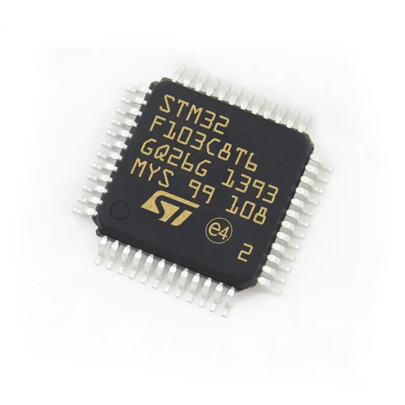
RP2040 vs STM32 vs SAMD21 vs ESP32-S3
| Raspberry Pi RP2040 | STM32F103C8T6 | ATSAMD21G18 | ESP32-S3 | Product Image |  |
 |
 |
 |
|---|---|---|---|---|
| Dev Board | Raspberry Pi Pico | Blue Pill | MKRZero, Seeed XIAO | ESP-S3, Seeed XIAO |
| Cores | Dual-Core | Single Core | Single Core | Dual-Core |
| Core Architechture | 32-bit ARM Coretex-M0+ | 32-bit ARM Coretex-M3 | 32-bit ARM Coretex-M0+ | Xtensa® 32-bit LX7 |
|
|
Flexible Clock up to 133MHZ | 72MHz | 48MHz | Up to 240 MHz |
| RAM Size | 264 KByte SRAM | 20 KByte | 32 KByte | 512 KByte SRAM |
| Flash Size | Up to 16 MByte external Flash | 64 KByte | 256 KByte | Up to 1 GByte external Flash |
| DIrect Memory Access | 12 x DMA | 7 x DMA | 12 x DMA | 3 x DMA |
| Wireless | None | None | None | IEEE 802.11b/g/n |
| Programming Lanuage | MicroPython, CircuitPython, C/C++, Arduino | C alike, Arduino IDE | C alike, Arduino IDE | Espressif IDF, Arduino IDE, CircuitPython |
| MCU Power Voltage | 3.3VDC | 3.3VDC | 3.3VDC | 3.3VDC |
| USB Interface | USB 1.1 Device and Host | USB 2.0 Full Speed | USB OTG | USB OTG |
| Program Laoding | USB Mass Storage, UF2 | External device, Serial | USB, UF2 | USB, UF2 |
| GPIO | 30 x Digital Input/Output | 37 x GPIO | 38 x GPIO | 45 x GPIO |
| High-Speed PIO | 2 blocks, 8 x State Machine, 8 × 10 | No | No | No |
| ADC | 4 x 12-bit | 10 x 12-bit | 12 x 12-bit | 2 × 12-bit SAR ADCs, up to 20 channels |
| DAC | No | No | 1 x 10-bit | 2 x 8-bit |
| UART | 2 | 3 | 6 x Sercom (UART, I2C, SPI) | 3 |
| I2C | 2 | 2 | 6 x Sercom (UART, I2C, SPI) | 2 |
| SPI | 2 | 3 | 6 x Sercom (UART, I2C, SPI) | 4 |
| PWM | 16 | 15 | 20 | 2 × MCPWM |
| On Chip Sensor | Temperature | No | No | Temperature |
| IC Package | QEN-56 | LQFP-48 | 48-pin TQFP, QFN, WLCSP | VFQFN-56 |
| Retail Price | USD 1.00 | USD 3.50 | USD 3.15 | USD 1.20 |
Reference
In this week’s course, I learned various knowledge about embedded programming. As a former embedded engineer, we will all retain the habit of studying datasheets. Based on the classification of microcontrollers that are currently on the market, I selected several important specifications to study and read, such as RP2040,STM32,ATSAMD12,ESP32-S3.
In terms of length, RP2040 is currently the most detailed datasheet.According to the latest information, 640 pages of information detail the origin, parameters and usage specifications of the chip. As a former embedded engineer, we often pay more attention to the performance processing parameters of the chip and some interface design references, so that developers and engineers can design chip reference development boards according to their own needs.
Programing on XIAO ESPS3
1. Install Arduino IDE and board manager
Installing the Arduino Ide is a relatively painless task. But when I installed the board manager according to Seeed XIAO’s WIKI, an error occurred. The main reason for the error was due to the timeout of loading the github library resources. After continuous inquiries, I found the reason. Due to VPN problems, I was unable to obtain the library files in real time, which resulted in the loading failure.

2. Sample code for LED Blink
After successfully installing the library files, you can finally select the board model in the Arduino IDE. I used the Blink program in the sample program. By compiling and uploading the program, I can finally see that the right LED of XIAO ESP32 flashes.


3. Microphone Testing for XIAO ESP32 Sense
According to XIAO’s product introduction, the board integrates peripherals such as a microphone, so I will follow the tutorial to test the microphone peripherals and train through edge pulse.
- A. Initialize the Micro SD card: Since XIAO ESP32 requires a memory card in FAT32 format, I first found a memory card to initialize it to facilitate subsequent storage of sound files collected by the microphone.
 - B. Test the microphone function and monitor the sound through the serial port: After compiling and uploading the program, we can set the corresponding baud rate through the serial port for signal observation. After shouting to XIAO loudly, we can clearly see the signal displayed on the serial port. The value increases and changes occur.
Sample Code for XIAO ESP32S3 Microphone Testing
  #include <I2S.h>
        void setup() {
          // Open serial communications and wait for port to open:
          // A baud rate of 115200 is used instead of 9600 for a faster data rate
          // on non-native USB ports
          Serial.begin(115200);
          while (!Serial) {
            ; // wait for serial port to connect. Needed for native USB port only
          }
          // start I2S at 16 kHz with 16-bits per sample
          I2S.setAllPins(-1, 42, 41, -1, -1);
          if (!I2S.begin(PDM_MONO_MODE, 16000, 16)) {
            Serial.println("Failed to initialize I2S!");
            while (1); // do nothing
          }
        }
        void loop() {
          // read a sample
          int sample = I2S.read();
          if (sample && sample != -1 && sample != 1) {
            Serial.println(sample);
          }
        }

4. XIAO ESP32S3 Sense Keywords Spotting via TinyML EdgeImpules
- A.Capturing the offline audio data:
As we all know, if you need to train an AI model, the first step you need to do is to obtain the original data set to facilitate subsequent model training. According to the tutorial, we collected 2 sets of data respectively with the keywords “hello” and “crail” through XIAO ESP32S3. Each set of data is about 10 seconds in length, and finally saved in the microSD card. Since I am currently just testing, there are not many data samples collected. If you want to conduct more accurate AI model training, more data sets will be more helpful for model generation.

- B.Uploading collected sound data to Edgeimpluse then make pre-processing and model defining:


Programing on XIAO RP2040
1.Install the XIAO RP2040 libaray
- Add the reference link to Arduino IDE preference setting.
https://github.com/earlephilhower/arduino-pico/releases/download/global/package_rp2040_index.json
 - Select the Board and Com Port as XIAO RP2040.

2.Use the button to light up the LED
In this program, I first referred to the schematic diagram to find the corresponding GPIO interfaces of the onboard RBG LED and buttons. I was familiar with Arduino programming and Neopixel library file control LED before, so I wanted to control the RGB_LED to turn on and off by pressing the button, and at the same time, long press the button to make the color of the RGB LED change. When the button is released, the light The color will stay in the state just shown.
Use the button to light up the RGB_LED
In this part, it is mainly used to call some library files and set the pins of the hardware connection, and at the same time define some parameters related to the library files. I set three pins here, define the number of RGB LEDs and detect double-press. button time.
#include <Adafruit_NeoPixel.h>
int Power = 11; // RGB_LED Power GPIO
int PIN = 12; // RGB_LED Signal GPIO
int ButtonPin = 27;  // Button GPIO
#define NUMPIXELS 1 // Numbers of RGB_LED
#define DOUBLE_PRESS_TIME 500 // Maximum time for double press detection in milliseconds
Adafruit_NeoPixel pixels(NUMPIXELS, PIN, NEO_GRB + NEO_KHZ800);
In this part, it is mainly the initialization part of the program. First, initialize the library file of the LED light. In addition, set the brightness of the LED light. Since the brightness of the lamp bead was too bright during the previous test, I set it in the initialization. In addition, some pin function settings are performed.
void setup() {
  pixels.begin();
  pixels.setBrightness(50);  // Set the LED brightness
  pinMode(Power, OUTPUT);
  digitalWrite(Power, HIGH);
  pinMode(ButtonPin, INPUT_PULLUP);
  // Set the button pin as an input and enable the internal pull-up resistor
}
In this part, we mainly define some variable parameters, especially the initial value for the detection volume of key detection.
bool lastButtonState = HIGH;  // lastbutton State
int rainbowIndex = 0;  // Index for tracking rainbow colors
bool rgbOn = true;  // RGB LED initial state
unsigned long lastPressTime = 0;  // Time of the last button press
int pressCount = 0;  // Button press count
In this part, enter the main function part of the program. First, initialize and read the button status, then light up the LED and complete the operation actions I set before.
void loop() {
  bool currentButtonState = digitalRead(ButtonPin);
  unsigned long currentTime = millis();
  // Displays rainbow colors if button is not pressed and RGB LED is on
  if (rgbOn && currentButtonState == HIGH) {
    rainbowIndex++;
    if (rainbowIndex > 255) {
      rainbowIndex = 0;
    }
    pixels.setPixelColor(0, Wheel(rainbowIndex));  // Set rainbow colors
    pixels.show();
    delay(20);  // Adjust the speed to change how quickly the color changes
  }
  // Detect button state changes from unpressed to pressed
  if (lastButtonState == HIGH && currentButtonState == LOW) {
    pressCount++;
    if (pressCount == 1) {
      lastPressTime = currentTime;
    } else if (pressCount == 2 && (currentTime - lastPressTime <= DOUBLE_PRESS_TIME)) {
      rgbOn = !rgbOn;  // Toggle RGB LED state
      if (!rgbOn) {
        pixels.clear();
        pixels.show();
      }
      pressCount = 0;  // Reset press count
    } else if (pressCount > 2 || (currentTime - lastPressTime > DOUBLE_PRESS_TIME)) {
      pressCount = 1;  // Reset press count and start over
      lastPressTime = currentTime;
    }
  }
  lastButtonState = currentButtonState;  // Update button state
}
// Use wheel functions to generate rainbow colors
uint32_t Wheel(byte WheelPos) {
  WheelPos = 255 - WheelPos;
  if (WheelPos < 85) {
    return pixels.Color(255 - WheelPos * 3, 0, WheelPos * 3);
  }
  if (WheelPos < 170) {
    WheelPos -= 85;
    return pixels.Color(0, WheelPos * 3, 255 - WheelPos * 3);
  }
  WheelPos -= 170;
  return pixels.Color(WheelPos * 3, 255 - WheelPos * 3, 0);
}

Press the button light up the RGB LED;
Long-time press button to make RGB LED change color;
Release button the freeze the current RGB LED color;
Doube-press button to light off the RGB LED;