Week 3: Computer Controlled Cutting
The assignment:
1. Group Assignment:Click here
2. Individual assignment:
What is Computer Controlled Cutting? Computer controlled cutting is the usage of computer software to design objects defined by parameters to send to cutting machines, such as laser cutting machines and vinyl cutting machines.
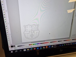
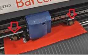
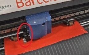
A. Vinylcutter Roland GX-24:For the vinylcutter I wanted to do 2 things. 1. Learn the settings of the vinylcutter and making adjustments to get the machine to work right and make a test cut on a vinyl material. 2. Making a design/cut for my bag and transfer it with the heatpress.
My workflow:

 .
.
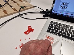
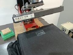
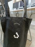
For this weeks assignement I also chose to design and produce something with the heatpress and print on textiles.
I made a design with my name and an upcycling logo. File: Textil print.Just remember to mirror the image/ text before saving.
Getting the heatpress ready I warmed it up to 165 degrees and set the timer to 20 seconds. I did 2 presses.
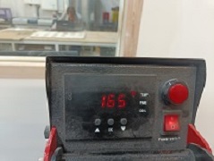 Warming up to 165 degrees
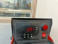 20 seconds for each press
 Let it cool betweeen each press
 Done
Done
B. Parametric design in Fusion 360.
Parametric design lets the model adapt to changes in the parameters and create new sizes or configurations. Creating a press-fit piece with parametric design in Fusion 360 involves using sketches, parameters, and constraints.
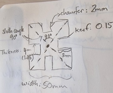
As you can see on the analog sketch above I had already calculated the dimensions. Instead of manually creating every part of the model, parametric design allows you to define logical rules and parameters. The following can be used as steps to follow if you want to go from analog sketch to a parametric design:
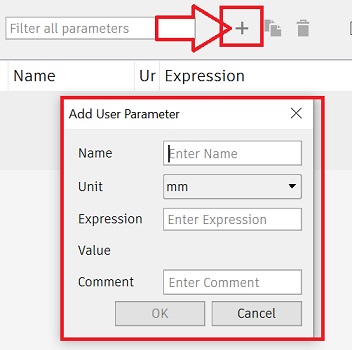
- First go to change parameters in the “modify” menu
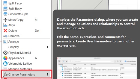
- Then you open a dialog box by clicking on the +symbol and add the parameters.
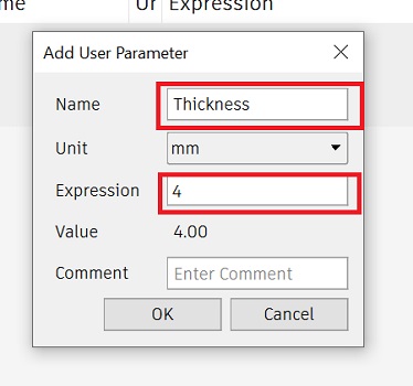
- In this example I start with the thickness of the material which is 4mm and press OK
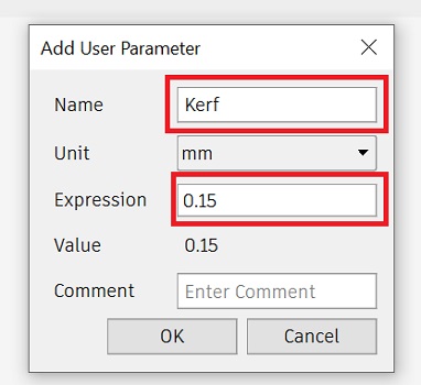
Then I do the same again by clicking on the +symbol and add the next parameter. This time the kerf = 0.15 mm
And continue doing this for all the parameters untill I had all the parameters.
Parameters for pressfit and parameters in the sketch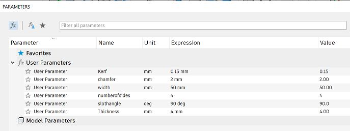
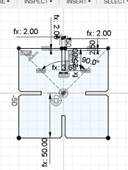
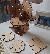
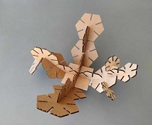
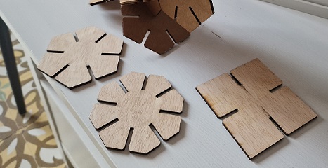
Later I wanted to change the number of sides eg. from 4 to 6 and 8 without changing anything else. I could easily do this just by altering the number of sides in the “change parameters” menu as you can see in the originale *dxf file below
Reflections:
As Fusion still is new to me I struggled a bit hanging on the classinstruction. Afterwards I had some help from Tony who shared his file with me so I could see how he had done things. I then looked into it in my own pace and figured out how to do my parametric design. I had to concentrate on that instead of paying attention to Grasshopper class.
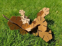
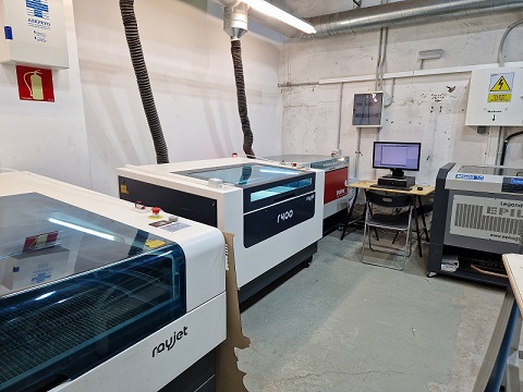
Lasercutting
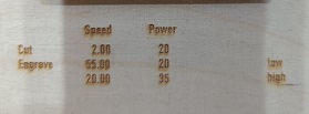
Then I cut the pressfit. The kerf settings weren´t right so I had to adjust. For the kerf test we had made a comb design. The separation between teeth decreases in steps of 0.05mm. My settings for the kerf were 0.15mm. Now I went for 0.20 mm. After testing again the fit was better and I could start cutting the project. To test materials I both cut in plywood and cardboard.