Computer Controlled cutting 2
Group assignment requirements
The group assignment for this week is the following:
- Characterize your laser cutter’s focus, power, speed, rate, kerf, joint clearance and types.
- Document your work on the group work page and reflect on your individual page what you learned
Laser cutting machine specs
A picture of your laser cutting machine
Describe/list the available features and key settings of your laser cutter.
Machine name: Thunder Laser
Machine max power in Watts: 100
Machine bed size (work area): 600 mm x 900 mm
Machine type (CO2 or fiber): CO2
Toolpath generation software used: RD Works
Safety
Describe the safety measures around using your laser machine. Fire extinguishers, safe distance, etc
For Safety - Keep the door of the laser cutter closed. - The air pump should be turned on so you don’t inhale toxic fumes. - Make sure the material cut with the laser cutter is safe to be used. - Stay at a safe distance. - Don’t leave the room when the laser cutter is working. - Make sure there is a fire extinguisher around.
Focus
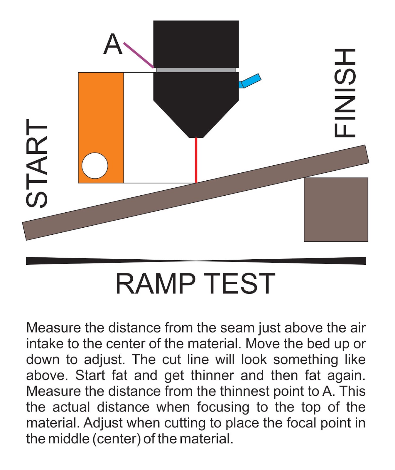
The focus position of the laser cutting machine is the relative position between the focus and the upper surface of the workpiece, based on the machined material surface.
Perform one of those 2 Focus tests, take pictures and log the results test1 test2


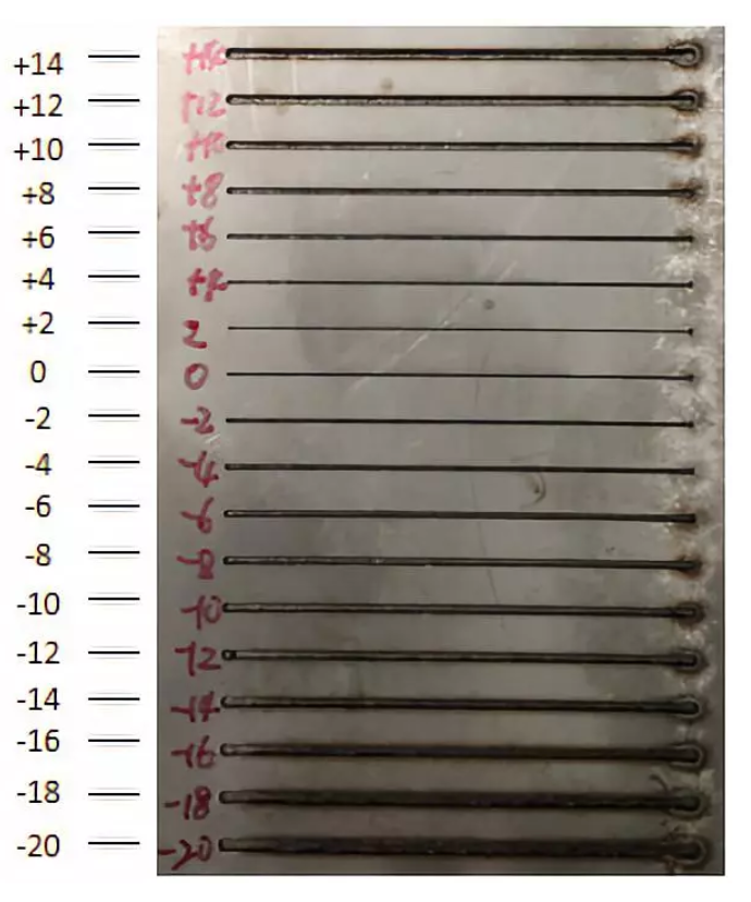
In this test, we added a line of length 20 cm to be cut with the laser. We changed the z-axis distance each time to check at which focal length will the cuts be clearer and better.
Note that the numbers refer to z-axis distance shown on the machine. The zero in which we started with is 3003.8 mm is equal to 10 mm, and the best result was at 3006.0 mm which means 10 mm + 2.2 mm = 12.2 mm
As per the test performed, we found the optimal distance between the lens and material to get the best focus is 12.2 mm
Power and speed
make multiple small squares 2X2cm and cut them at different speeds and powers. Write on them the speed and power of each manually after cutting before taking the picture
 This week we got to know how to adjust the sittings to end up with the best cutting results by going through a number of experiments. Find the steps of our experience below:
Computer Sittings
The first thing we did was preparing a basic testing sheet that includes a number of squares, then we adjusted the sittings where every square got a different colour with variable speeds and power. For example, S20 and P35. Finally, we uploaded the drawing to the machine. The propose of this experiment was to figure out the best power and speed options for laser cutting.


Machine Sittings
After adjusting computer sittings, we moved on to machine sittings. First, we used a small lego piece to adjust the distance between laser cutting head and the surface of cardboard to get the ideal distance (focal length).

Second, we had to select the location of the drawing on the cardboard sheet by using direction arrows, then press origin and frame to make sure that the machine is going to cut the drawing in the right location.

Finally, we pressed on start button to begin the cutting operation.

First Test
When we came to actually test on the machine, we noticed many materials available there. We decided to go with the most available material (cardboard) as a first try

When we did all the steps that are mentioned before, we closed the cover of the machine and pressed start
After the machine is done with the cutting you will hear a notifying sound
After that we got our results out from the machine and we labeled each one with the exact settings that were applied on before

We noticed that (S20 P35) is the best setting to cut cardboard without any burns, and it is used to cut the upper left piece and also the frame
Here are also some notes we took during the process

One of the problems we faced during the process was that the cardboard sheet is not straight and curved a little bit so some of the parts were close to the laser cutting head so they got burnt

There are two solutions to this issue, one is to tape down the curved parts of the cardboard, and another is to put weights like acrylic pieces just to straighten down the curvature of the cardboard and to make it an even surface

Acrylic Test
As an additional experiment we tried cutting on acrylic instead of cardboard, and we noticed that the settings differ from the cardboard settings

Acrylic mostly needs 2 rounds of cutting, and you can refer to the photo for 3mm acrylic settings
And here are the final results!

Test Outcome The material being tested is cardboard which is 2.0 mm thick. Multiple different speeds and powers were tested and the best values were found to be a power of 35 and a speed of 20.
Rate
The rate at which the laser pulses or fires. For this material we used a rate of 1000.
kerf & joint clearance
Cutting kerf is the amount of material that is removed by the cutting process. This information is crucial when designing joints since the design used must account for the cutting kerf to be able to fit properly. the kerf test generator
The second task is to find the most suitable cuts for joints in order to make a press-fit objects. We were able to find the perfect thickness for the joints for the cardboard material we are using to be fixed properly.
Steps
- We started by designing a comb-like objects with different thicknesses using Fusion 360.

-
We started with thicknesses from 1.40 mm to 1.30 mm.
-
Note upload the design file as DXF for the laser cutter to recognize it.

-
We then cut two pieces of the comb to check if it will fit properly.


-
Trying all ten cuts from 1.40 mm to 1.30 mm, all of them were loose.
-
we then made another similar design but for thicknesses from 1.30 mm to 1.20 mm.

-
Similarly, we uploaded the DXF file to the laser cutter then cut two pieces of the comb.
-
This time we found the perfect fit, which was 1.22 mm.

The test performed is the comb test/kerf test. The material used has a thickness of 2mm. The slot that worked best with the chosen speed and power settings had a thickness of 1.22mm in the design.
[Material thickness] - [best fit thickness] = 0.78 mm Kerf = 0.78 / 2 = 0.39mm
Sources
The information referenced in this page was found in the following sources: Source 1 Source 2 Source 3