Input Devices
Goal
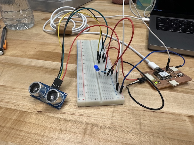
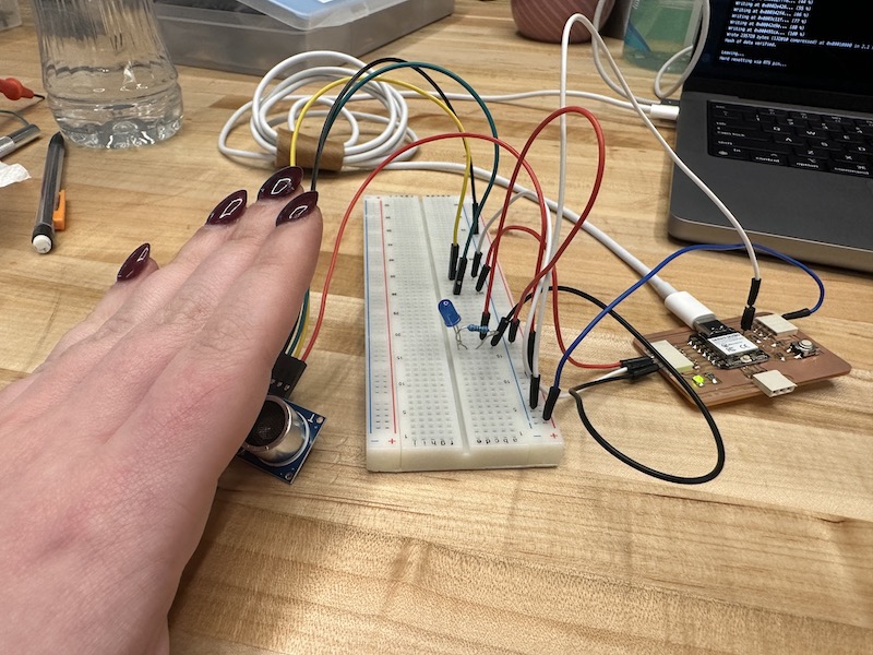
Using the development board I made in Week 8, I created a circuit that connected an Ultrasonic sensor and an LED. My intentions this week were to use the Ultrasonic sensor to fade an LED as my hand got closer to the sensor.
Setting Up the Circuit
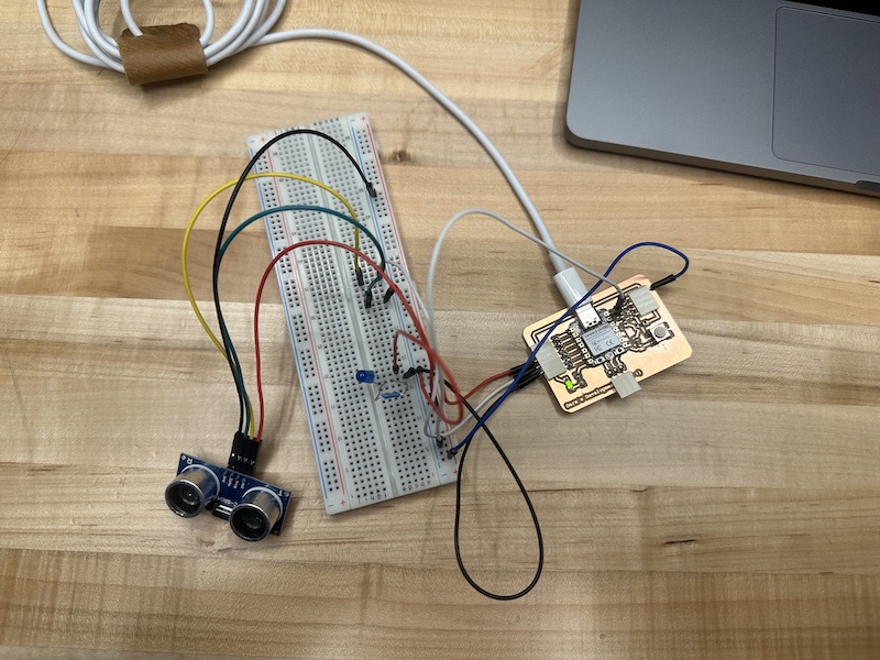
I connected the Ultrasonic sensor to my developement board with the GND to GND, echo to D3, Triq to D4, and Vcc to 5V. I then used a breadboard to connect an LED and resistor to pin D5 and GND. Although looking back I realize that the breadboard was an unneccesary middleman between the Ultrasonic sensor and the develpement board.
Writing the Code in Arduino IDE
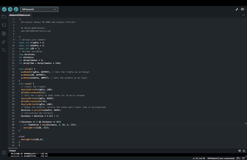
I repeated the sample code that my professor provided during our weekly lesson. To allow the data collected by the sensor to present the distance between itself and the object, I needed to use the function distance= duration * .034 /2, which is the length of time multiplied by the speed of sound and divided by to to account for the sound traveling to and from the object. I added the neccesary setup function for the LED and an if-else statement to direct the LED fade as my hand moves closer to the sensor. I used the measurements of 3-80cm to ensure better accuracy. I also wrote the code so that the LED would be high at 255 and low at 0.
Uploading the Code to the Board
I uploaded the code through Arduino IDE, however the developement board was not preforming the correct function. With some investigation and help from fellow peers, I realized it was because the pins are not internally labeled in numerical order. Rather, they are out of order and the pins I was using we actually labeled backwards within the code. Once I made this change the code executed correctly.