Electronics Production
Setting up the Circuit
Using the development board I made in Week 8, I created a circuit that connected an Ultrasonic sensor and an LED. My intentions this week is to use the Ultrasonic sensor to turn off the LED.

Using the SRM-20 and the Roland Software
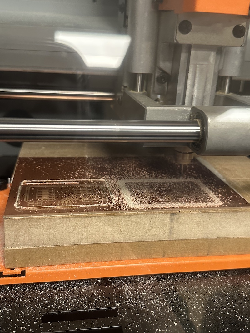
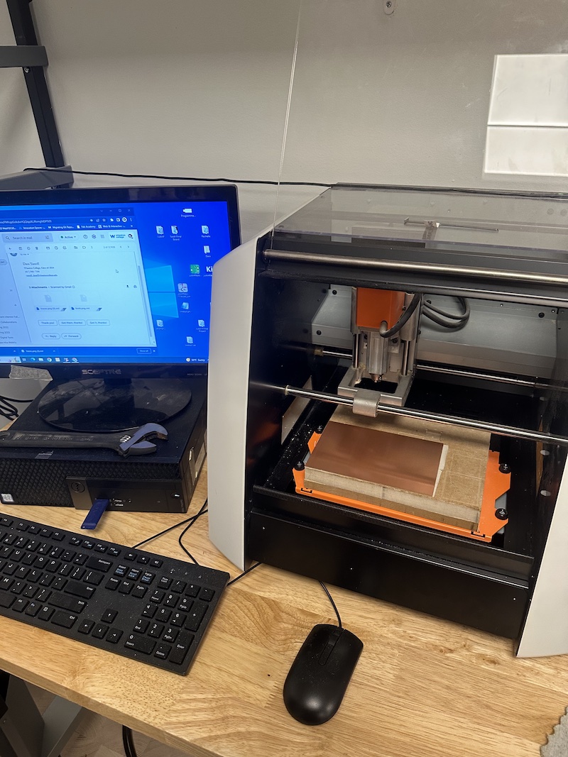
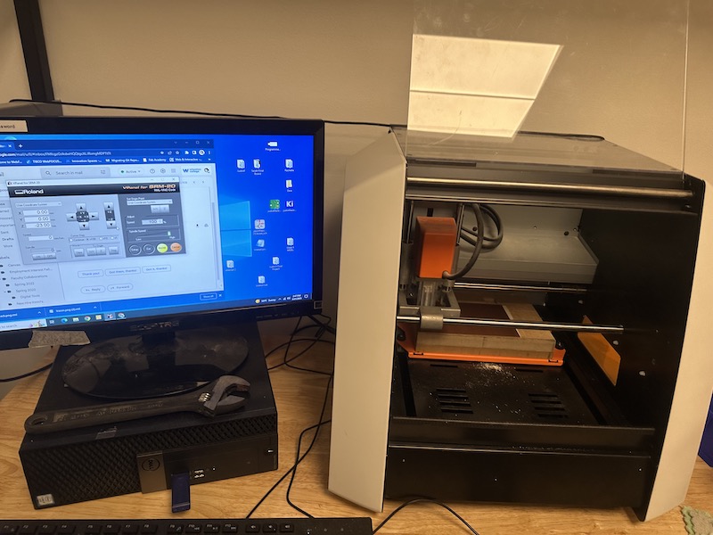
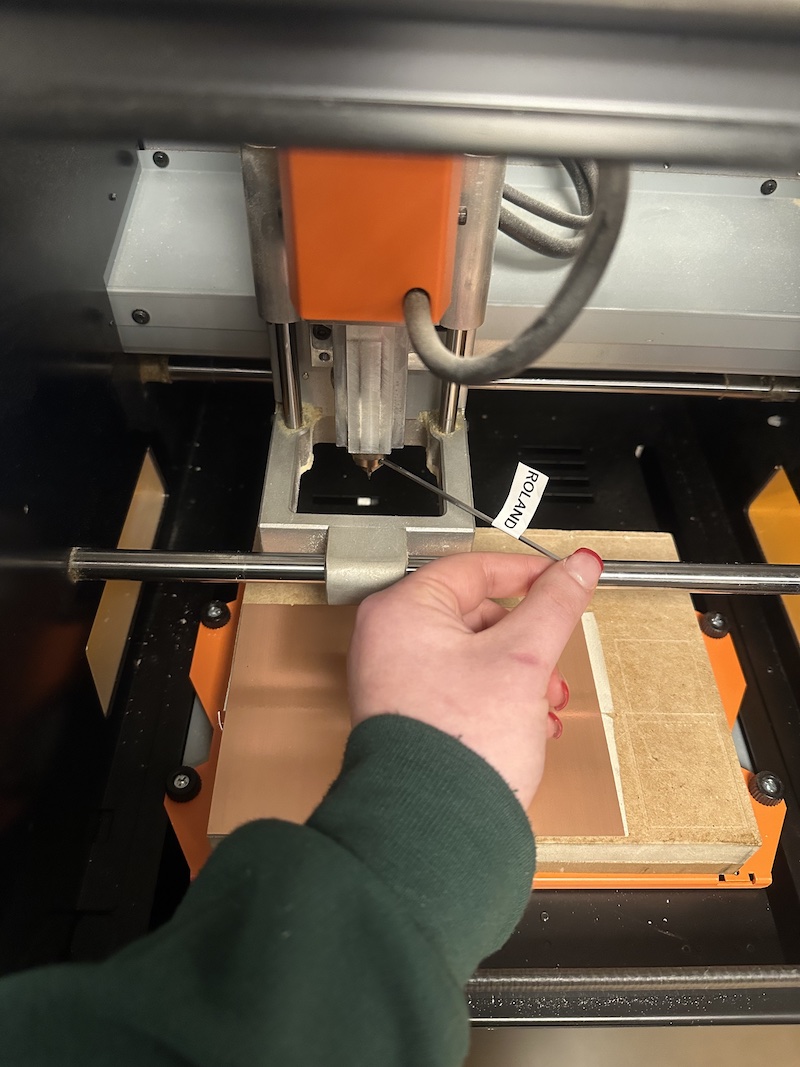
Moving the SRM-20 machine itself, I had to set the origin for the first mill of the traces. I arranged the x/y coordinates to be in the bottom left corner of the taped down FR1 copper clad sheet. I then set the z origin by loosening the collet, dropping the endmill to the copper clad, lowering the z coordinate, pushing on the copper clad only slightly while tightening the collet, and setting the z corrdinate on the computer. I then raised the endmill slightly, and it was ready and positioned to start the cut.
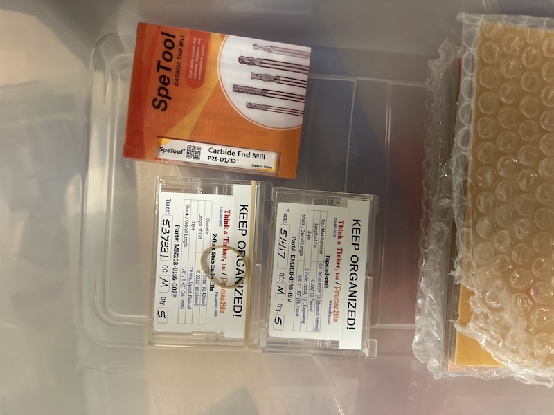
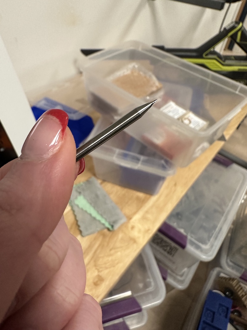
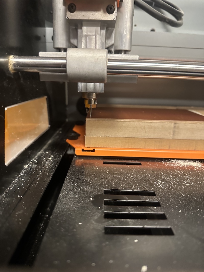
I cut the traces file first, then I had to change the endmill from 1/64 to 1/32 for the edge cut. To change the endmill I used the allen key to loosen the collet and replace the endmill. I then set the z origin the same way I had the previous, but kept the x/y origin the same as the previous cut.
 >
>
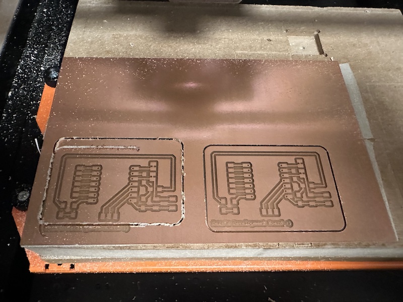
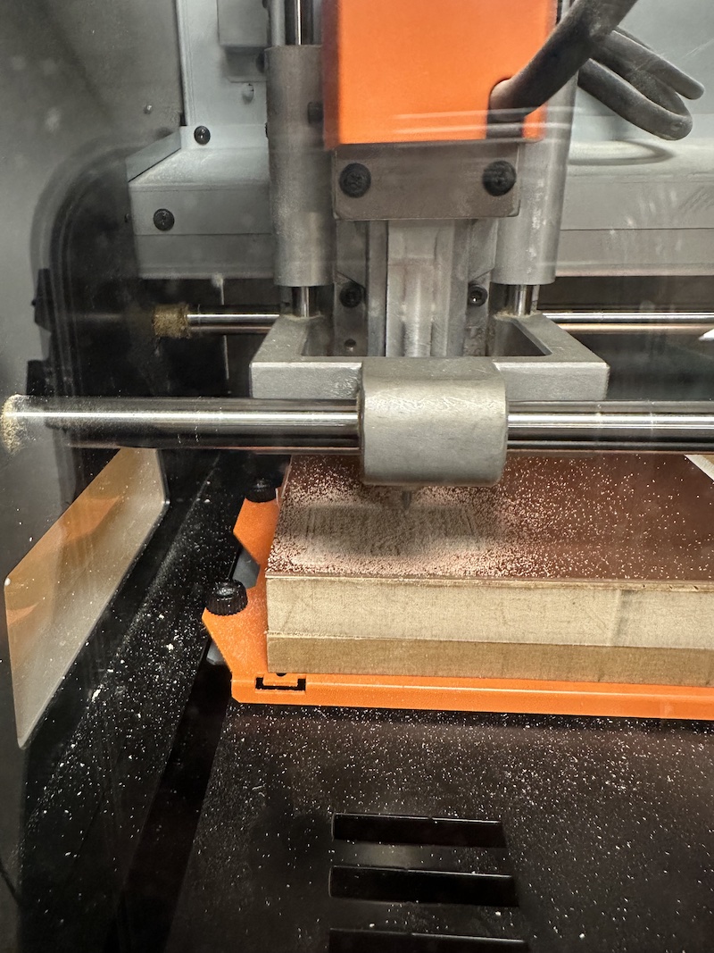
This cut was unsuccessful and was emergency stopped because the endmill was not fully tightened within the collet, causing the endmill to drag and yell a horrible noise. After tightening the collet I had to restart the machine. This resulted in the loss of orgin coordinates. I tried to guess at the original origin the best I could, but after completing the edge cut I was not satisfied with the messy appearance and jagged cuts.
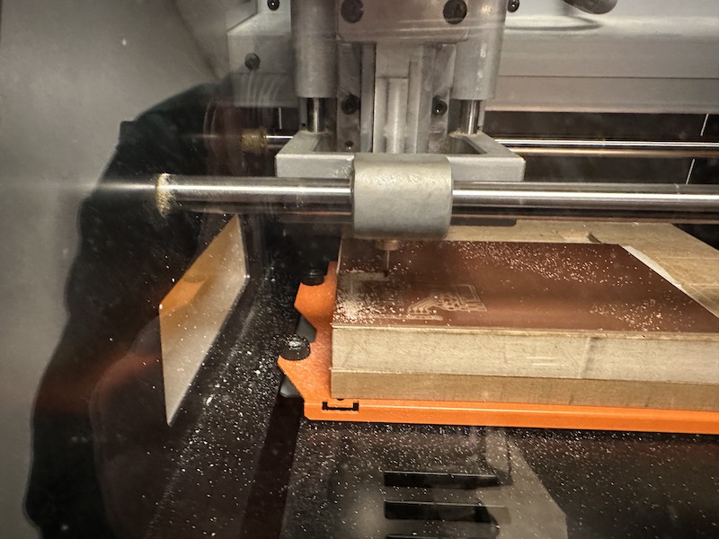
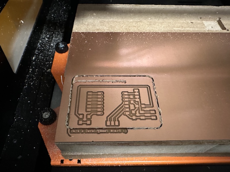
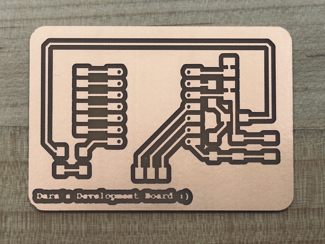
I restarted the process again, this time making sure that the endmill was secure inside the collet. It was successful on the second try!