Computer Controlled Machining
Individual assignment:
Group Assignment:
This week's group assignment was to learn how to cut designs from wood by computer controlled machining. We used Fusion 360 to create a design and Vcurve to communicate with the machine. I also learned the terminology associated with the machine and how to change its settings and bits.
Designing Using Fusion
I chose to design a bed for my cat this week. I sketched out a few of my ideas, chose one, and assessed the dimensions I wanted it to be. I then moved to Fusion 360 as the first step of bringing it to life.
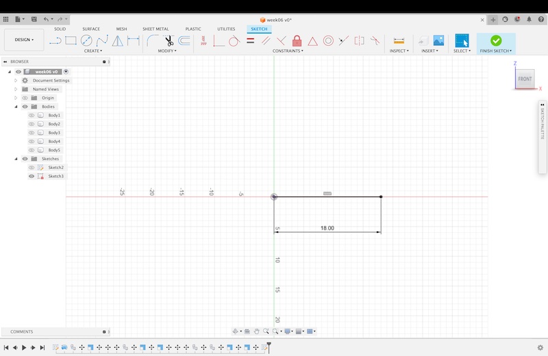
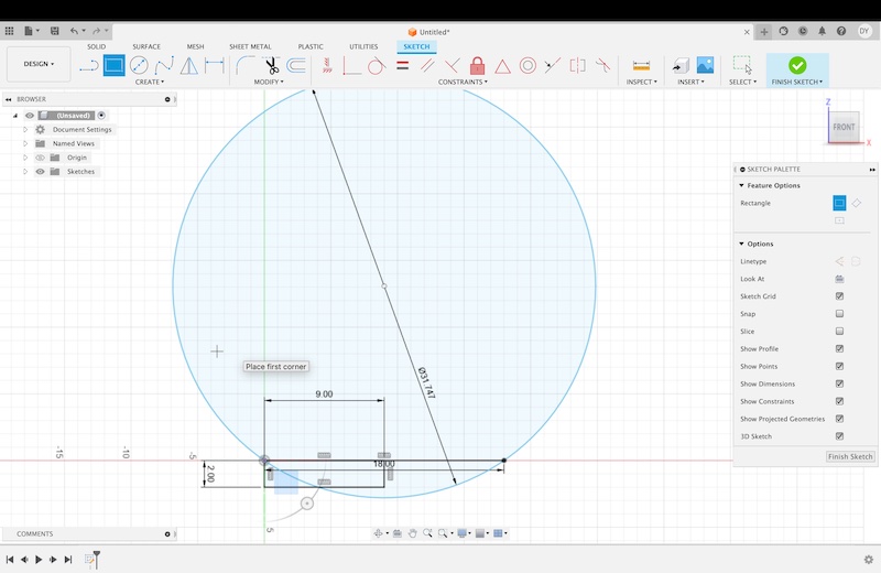
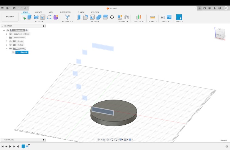
The first step in my design process was to lay the foundation dimension of my design, which was the bottom of the bed measuring 1.5 feet in diameter. I then sketched a circle on the same plane, making the first sketched line measure the bottom 7th of the circle. From there I built the sketch knowing I was going to use the revolve tool to form it into a solid. I did this by sketching the cross section of reach row. I oversestimated the thickness of the wood as 2 inches, but later I was able to adjust this dimension to be accurate, or .5 inches thick.
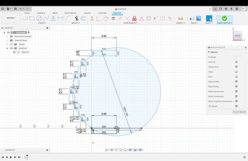
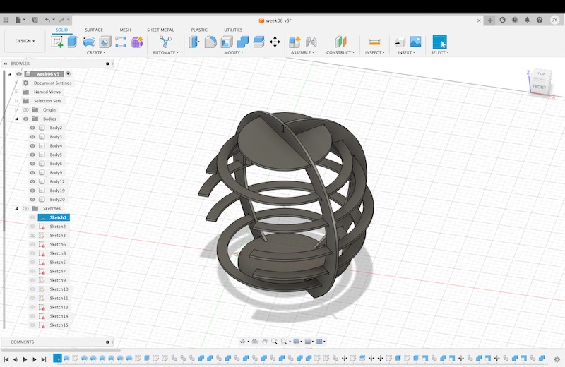
I then sketched a line through the middle of the sketched circle as a point to revolve the sketches around. I revolved all of the sketches, which left me with two cylinders and five rings. I wanted my kitty to have access to the bed though, so I had to change the degree of revolve for three of the rings. I changed the degree to 310.
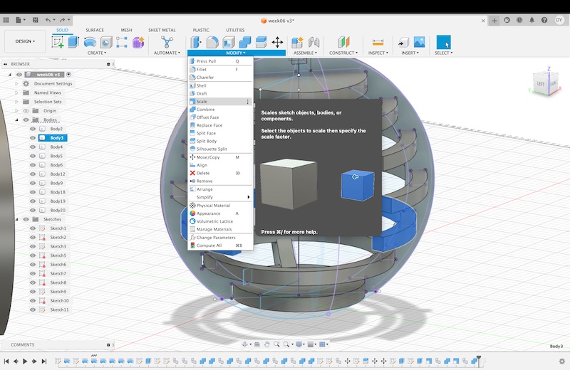
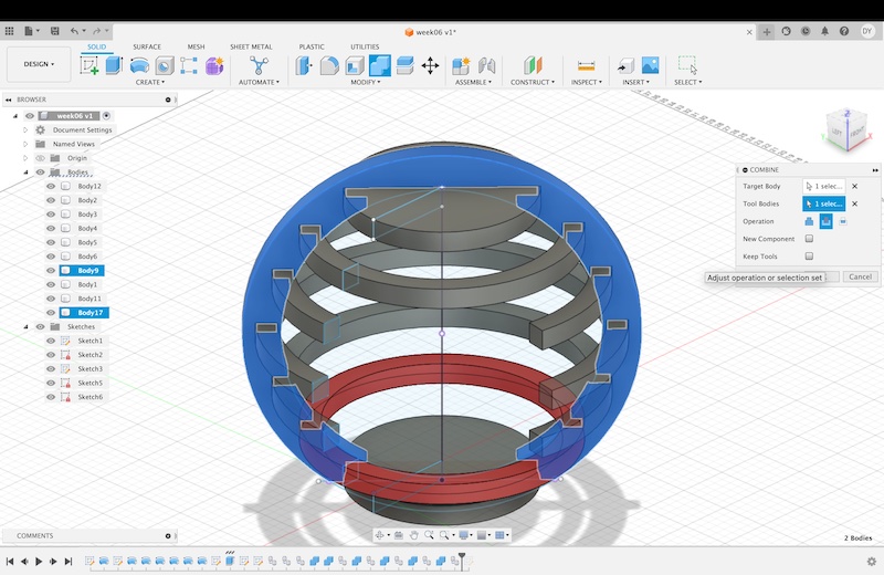
The next step was to create the supports. I made a circle that encompassed the rings, I couldn't encompass each of them evenly, but I decided that this is okay and won't hinder the design. I then used the offset tool to make another circle outside of the original sketch by 2 inches. Once these sketches were created, I extruded them by .5 inches. Then, I scaled each of the cyclinders/rings by 1/32, to ensure that the pieces would fit together snuggly. I then used the combine tool with the target of the bigger circle and the tool of each scaled ring to cut into the bigger circle. What was left is the support with a cut made for the scaled ring, and the orginal ring. I continued this process with all seven pieces.
After this was finished, I copied and pasted a second support. I cut it in half to make a second support for the back of the structure. I moved it into place. I then created a way for them to link together using a sketch and extruding the sketch to cut through the other support. Then repeating the process with a 31/32 dimension ratio to create an extension that would lock into it.
As mentioned earlier, I overestimated the thickness of the wood we are using in the lab, so I had to change the original sketch dimensions. Luckily, none of the proceeding features were unable to accomodate the change.
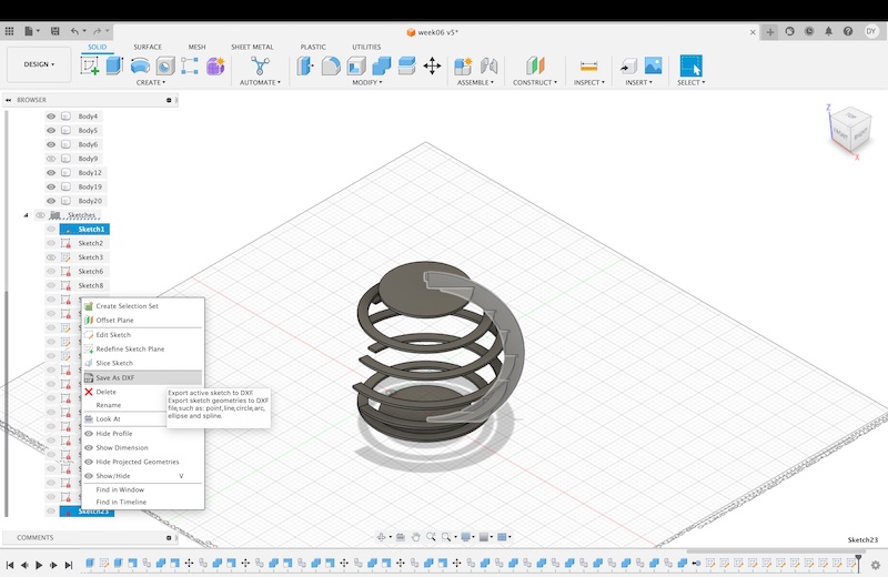
The final step in fusion is to create a sketch from each body using the project tool, and to save it as a DXF file.