3D Scanning and Printing
This weeks cycle was learning how to 3D scan an object, addressing the limitations of our Fablab's 3D printer, and making a small object that could not easily be made subtractively with these limitations in mind.
Using my Iphone, I searched for apps that are used for 3D scanning. I found quite a few, but I was recommended to one called MagiScan. I liked the design of the app itself and the scanning process was very intuitive, however the scan would not upload. This forced me to try another recommendation, which was Kiri Engine. MagiScan used your camera in live time with VR characteristics such as a dome over the object, while Kiri Engine has the capability of synthesising 70 pictures to create the scan. It prompted me to take the pictures in as many angles as I was able to. I did so successfully, and it gave me multiple options to edit the quality. I was satisfied with all the default settings, except for the file type, which I changed to STL for potential printing purposes. After I pressed complete, it took a few minutes for the the scan to fully process. Once it was completed it presented the scan, which was impressively detailed. I could not export the file though, sadly it cost money, but overall the scan was a success.


I worked in a group of my peers to test our Prusa MK3S+ 3D printer's capabilities in terms of bridging, overhangs, holes, and column printing accuracy. Using a stl file from Thingiverse that included all of the previously mentioned properties at varying measurements (0-80 degree overhang, 5mm-25mm bridge, etc.). The print took about an hour, and after it was finished we observed any unintentional differences between the file versus the physical print.

We found that the printer could handle an overhang of up to 80 degrees, however not without some shifted/unaligned layers starting at 60 degrees.
The printer was able to print a bridges ranging from 5mm to 25mm, however there was an small droop in material on the 25mm bridge.
Both the columns and hole portion of the print were preformed accurately.
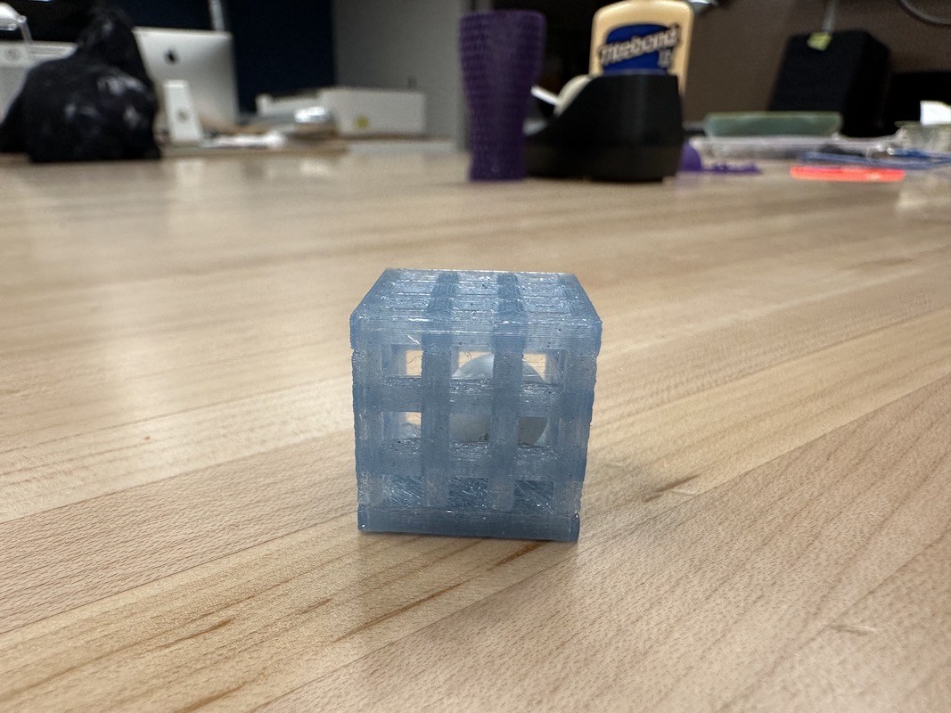
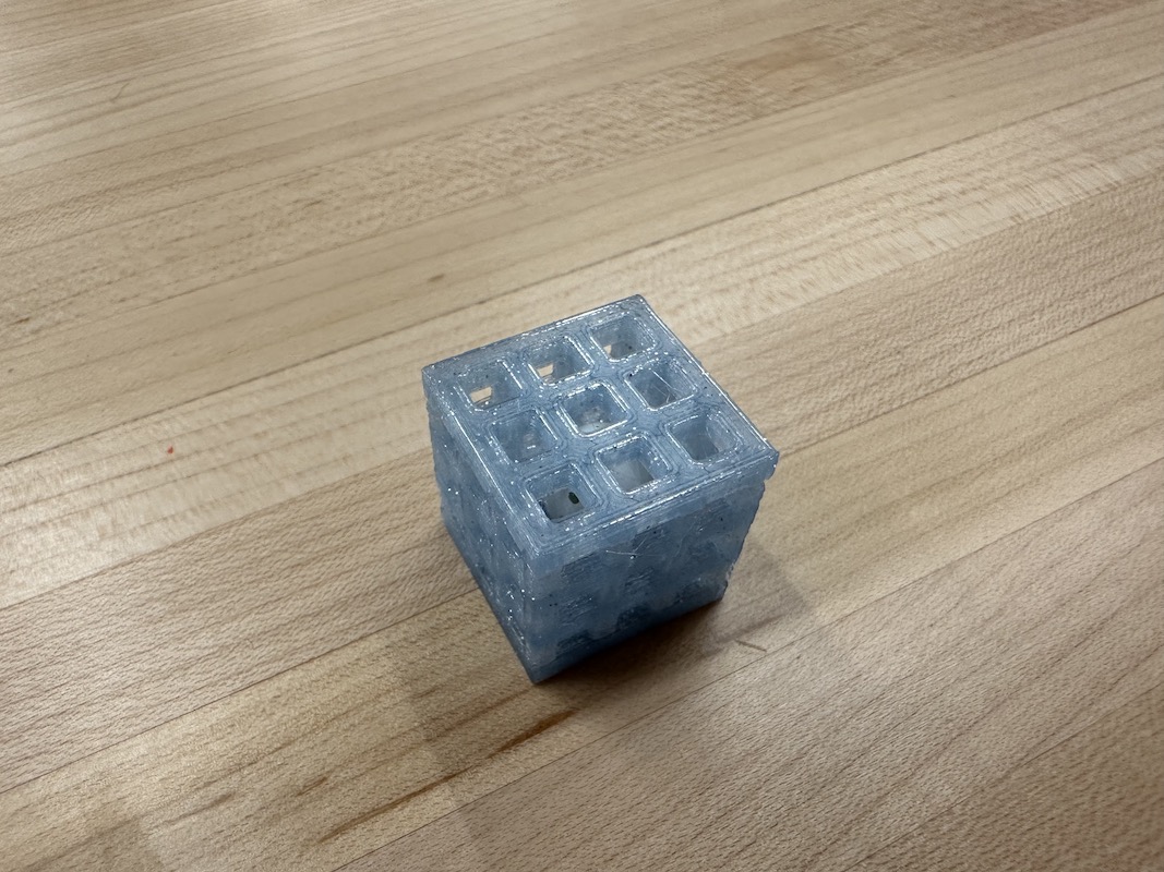
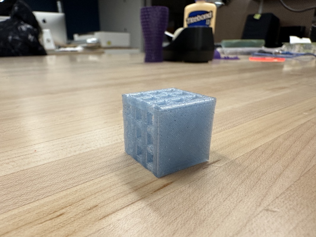
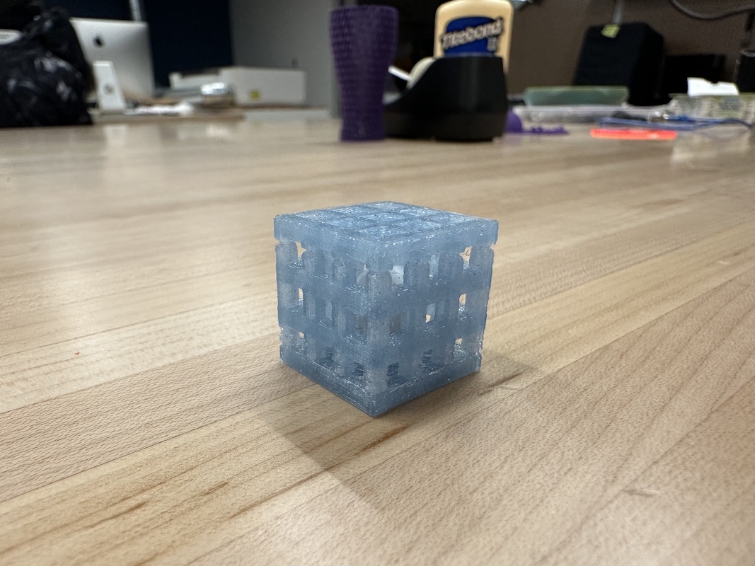
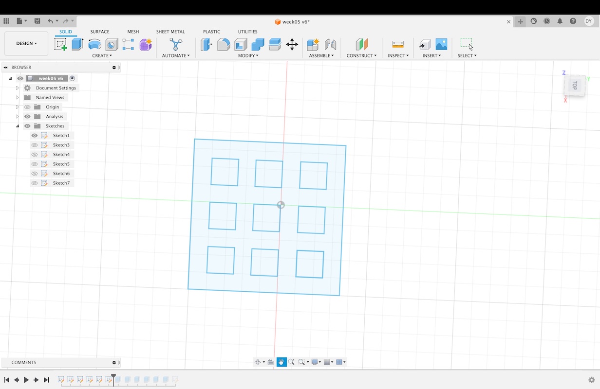
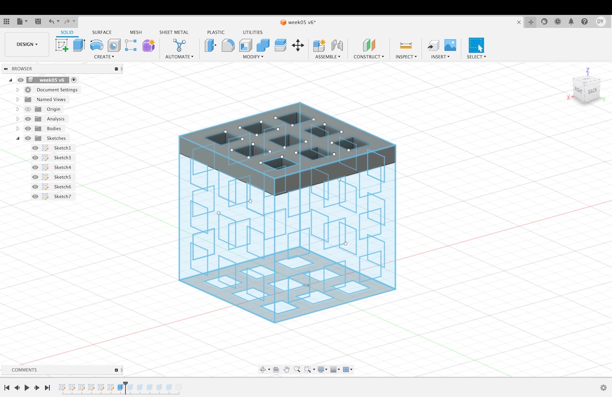
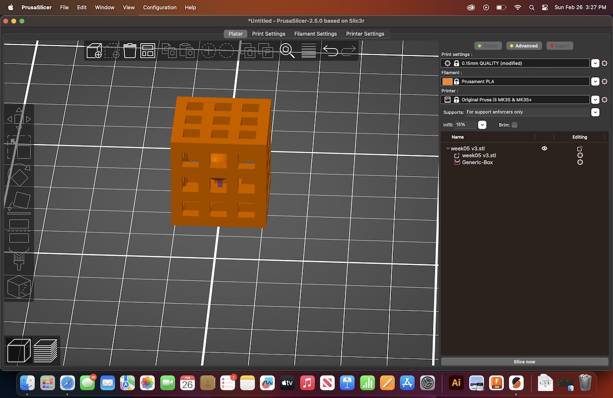
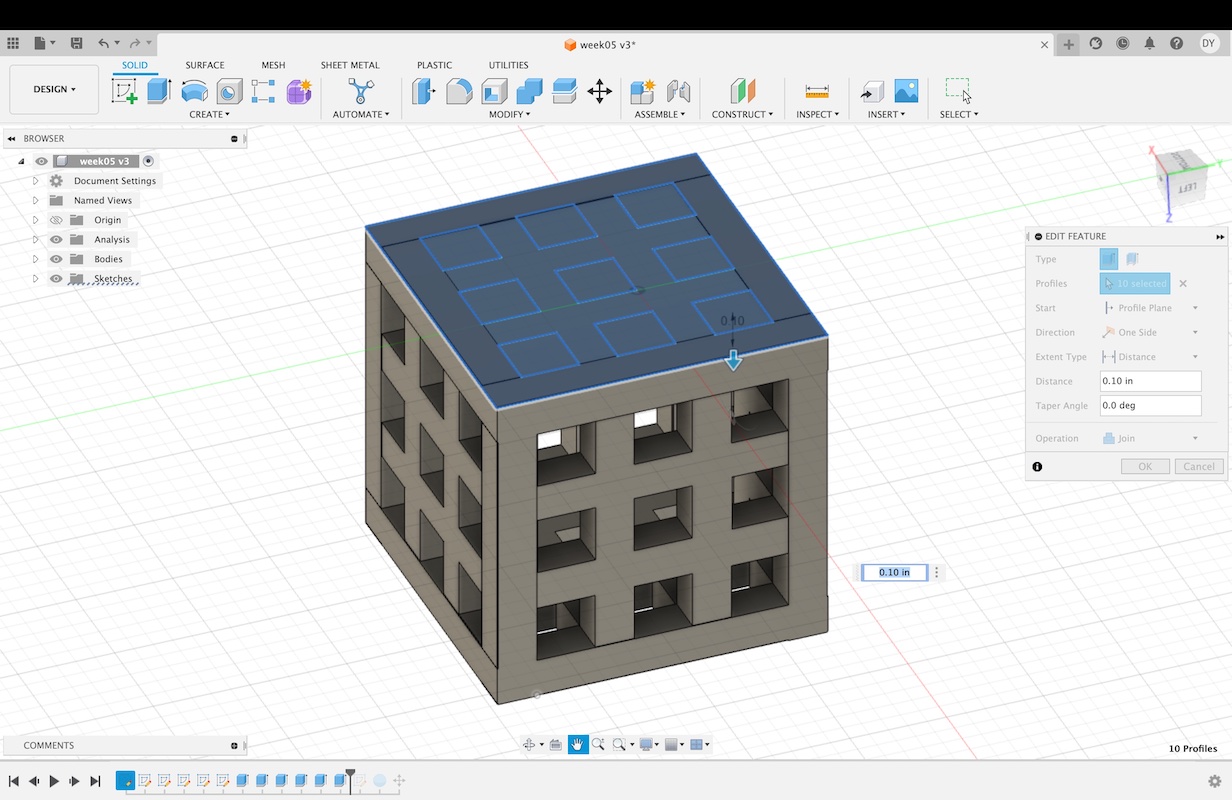
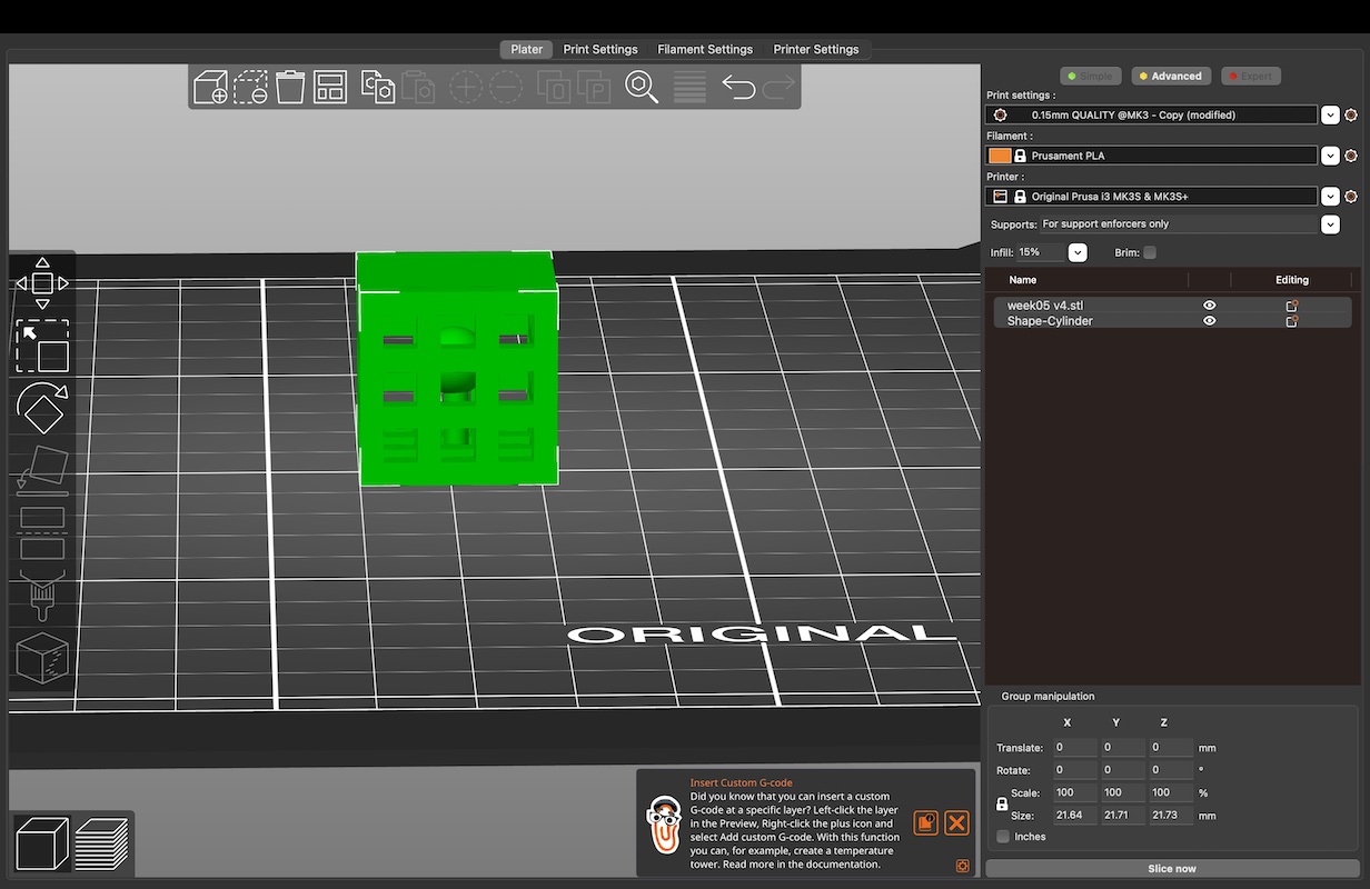
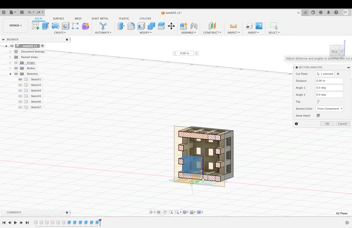
My first design failed in the 3D printer. Using Fusion 360, I designed a cube-shaped cage with a sphere in the middle, unconnected to the walls. I did this by sketching a 2inx2in square, then I sketched another square that measured .15ix.15in and copied and pasted it eight times. I aligned the smaller squares in an even 3x3 form, within the larger 2x2 square. I copied and pasted this sketch five times, and arranged them to create a cube.
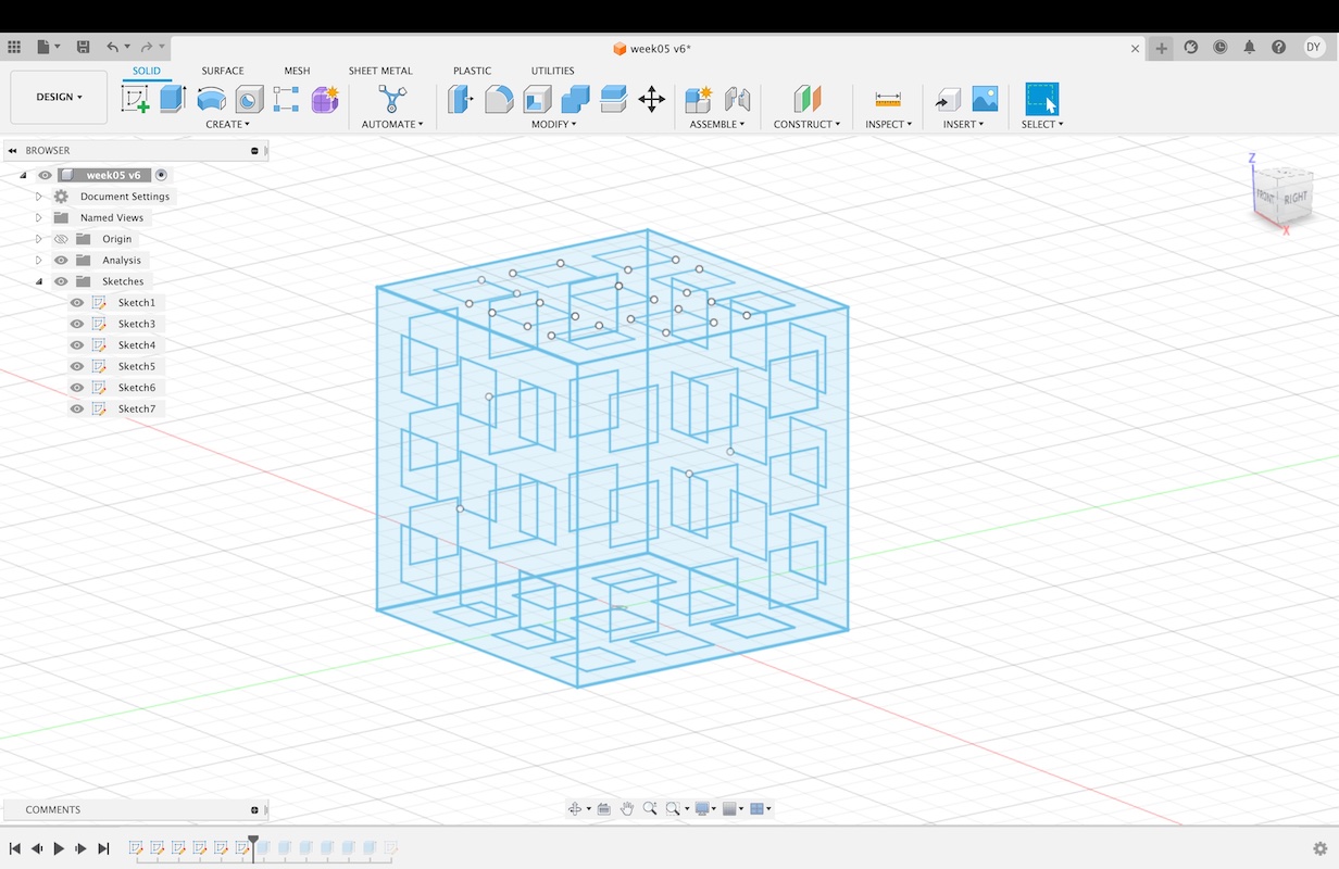
I then extruded the area inside the 2x2 square but outside of the .15x.15 squares. I did this on each side, always extruding inward towards the center of the cube, as to keep each side the same length and maintain the equal cube measurements. After creating the cage I used the sphere tool to create a sphere with a diameter of .25in.
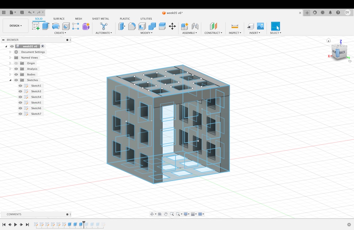
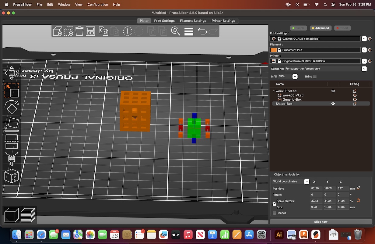
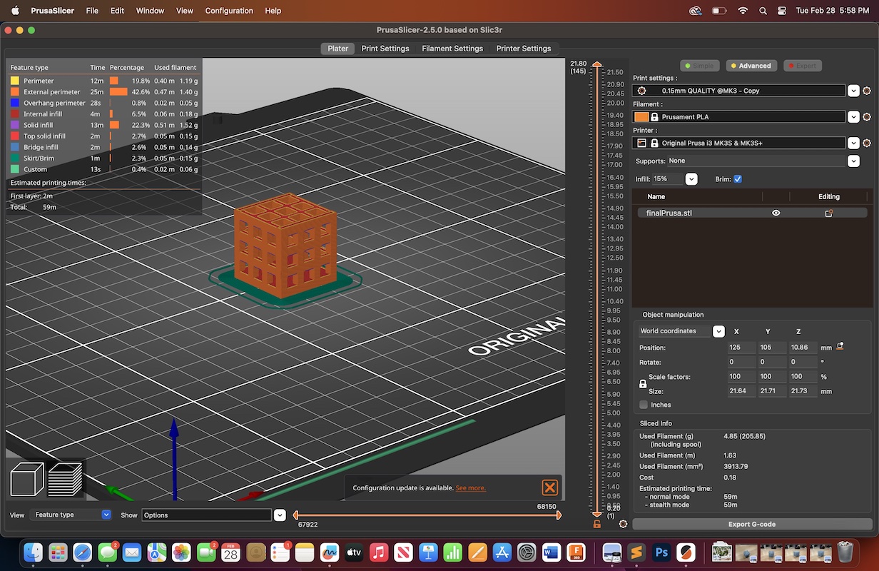
With the design finished, I exported the file as an STL to open in PrusaSlicer. In PrusaSlicer, I set the infill to 15%. I then created a support for the sphere so that when removed, the sphere would be loose inside the cube. I made the support settings for support enforcers only. I then added a box shape as a support, scaled it down and increased the height enough that it would fit within the empty space in the middle of the cage, on the bottom of the cube. I connected it to the sphere, and made sure that the only other contact that it made with the design was on the hot bed of the printer. I then selected slice now, then export to G-code. I made sure to save the G-code file to the SD card that is used to communicate files to the 3D printer.
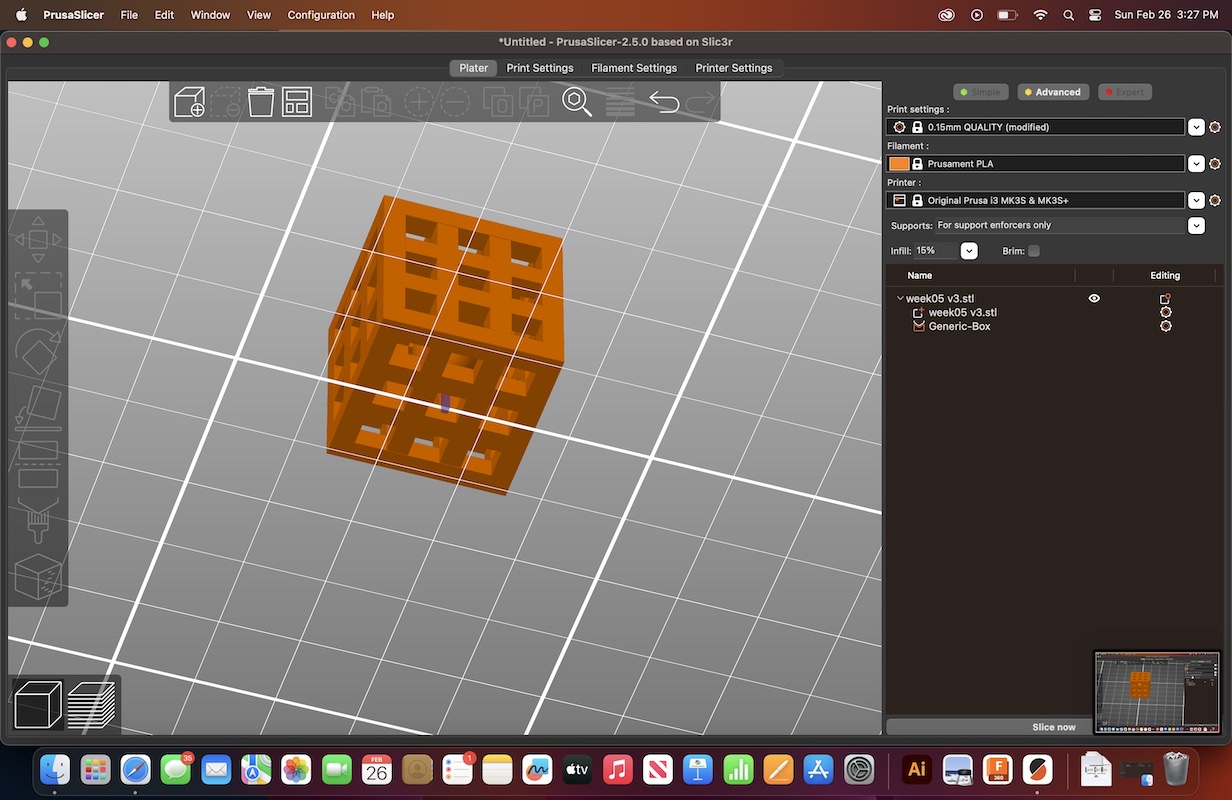
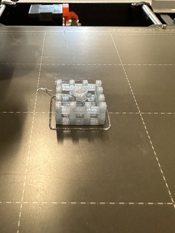
Moving to printing process itself, I preheated the printer, then loaded my prefered color of PLA filament, and selected my file from the menu of the Prusa. It took action and started printing. However I failed to realize, even after examining the STL file in PrusaSlicer, that the print was not going to take the path that I anticipated. Rather than laying the material in a weaved, straight-line grid formation, the printer laid the .15in squares first, then filled in the surrounding material with infill. This caused the top face of the cube to fail as the printing PLA had nothing beneath it to support it from falling into the cube itself. As soon as I noticed this was happening I removed it from the printer and began brainstorming solutions.
My proposed solution was to redesign the cube to have a solid bottom, and flip the design in Prusaslicer so that the solid bottom would print as the top instead. This would make the layout of the print path more conducive to having no supports. I know the printer is able to bridge the gap of the cube because of the group testing we conducted this week.
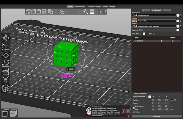
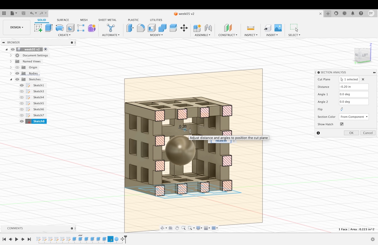
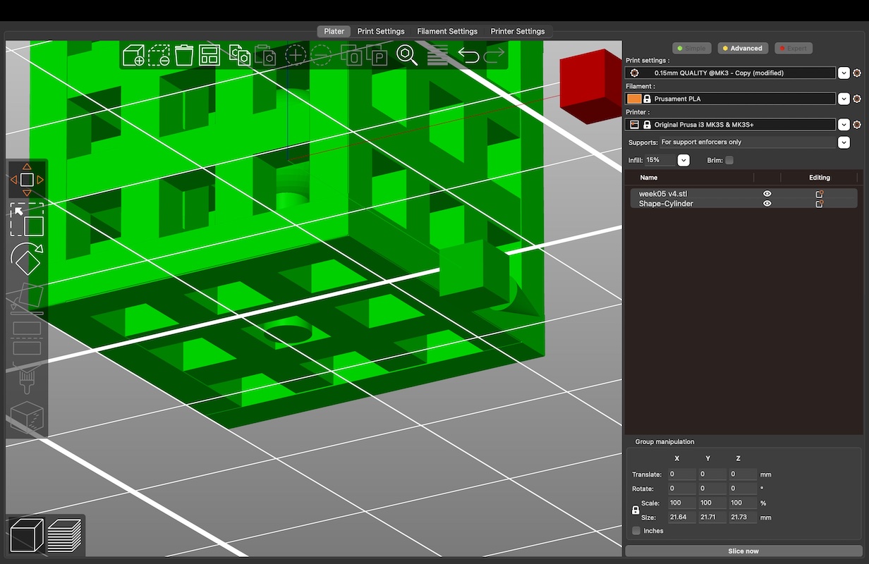
When working in PrusaSlicer, I also changed the shape of the support this time by making it cylindrical rather than rectangular. I did this in hopes that the support would be easier to extract from the cube.
Again I sliced and exported the file to G-code, and saved the file to a SD card to bring to the printer. I started the print, but it failed again. This time, it was because of the support and sphere inside the cube. I couldn't exactly assess what caused the print to fail however I surmise that the support was not thick or sturdy enough to uphold the sphere without breaking off of the hot plate. Time to figure out the next solution.
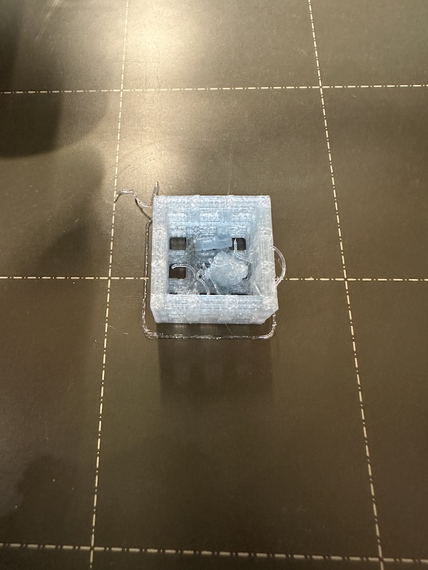

Luckily, I was in the lab talking to one of my peers about his own project for this week. He had a very similar idea, but instead of designing and printing his own sphere he was adding a marble into the middle of the sturcture halfway through the print by pausing/resuming it. I decided to adapt this idea to my own project.
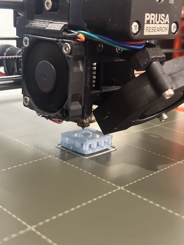
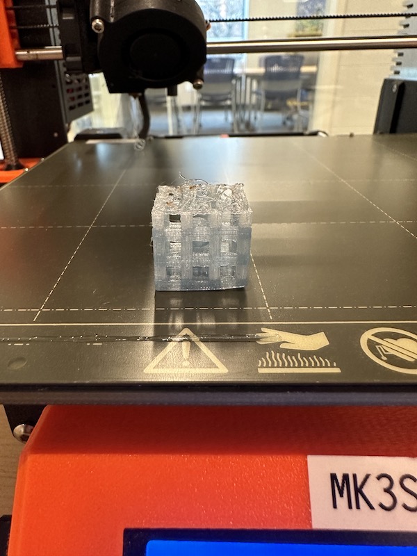
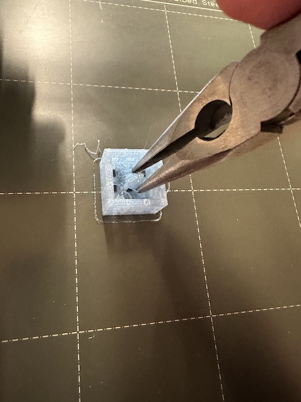
My print was much smaller than his, so I had to add the marble more towards the end of the process. My previously failed print was still on the printing bed, so I decided to extract the failed part of the design/print and add the marble into the middle of the cube. The print was still unsuccesful because the material shifted on the bed while printing.
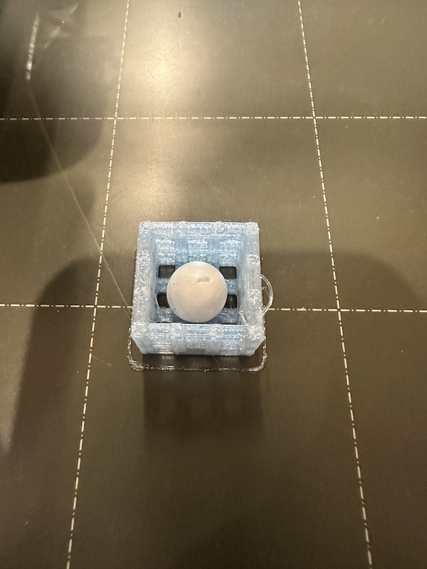
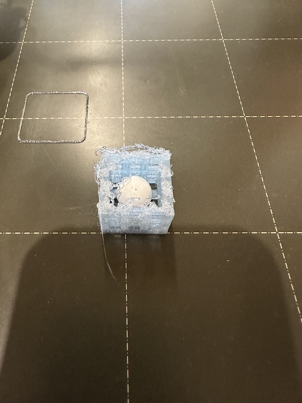
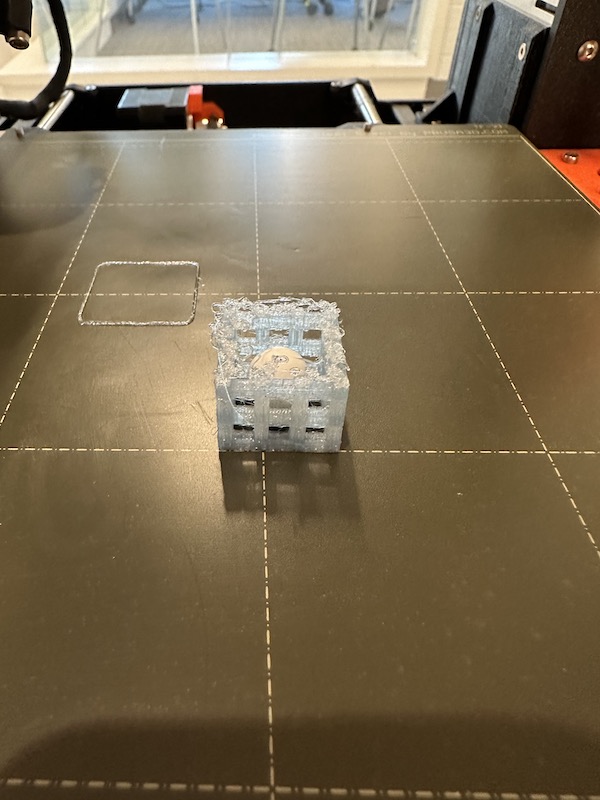
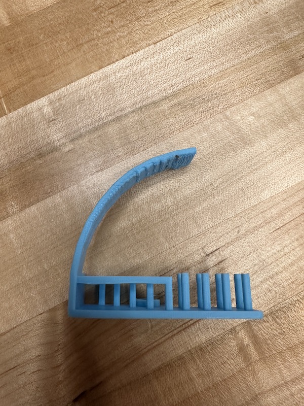
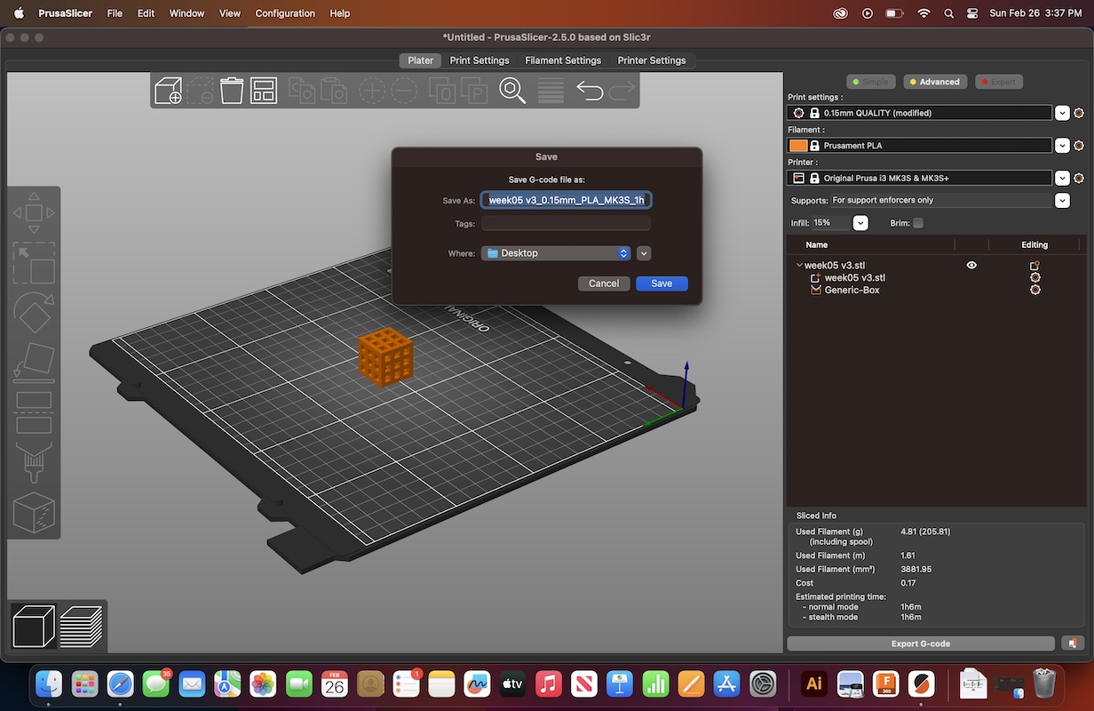
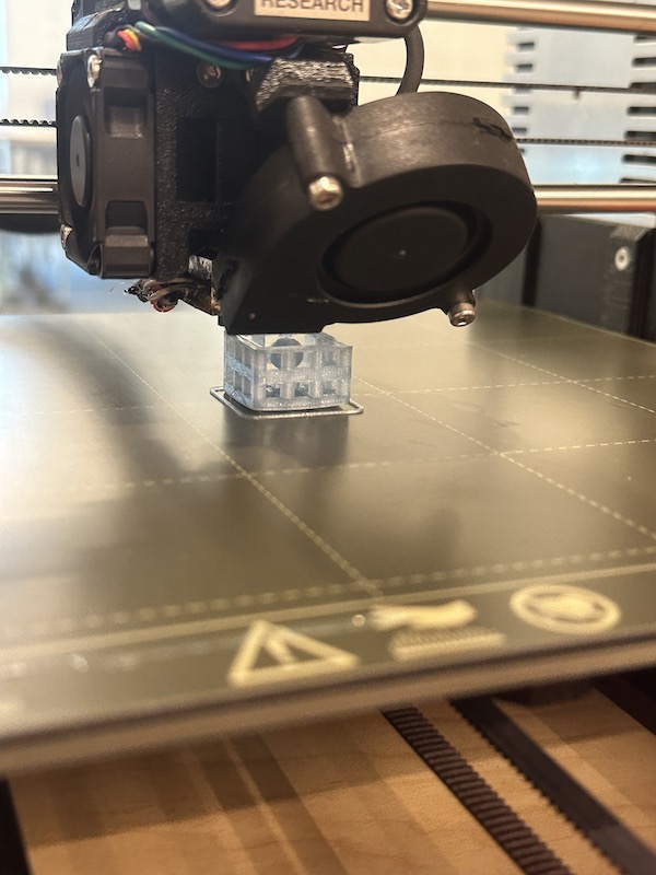
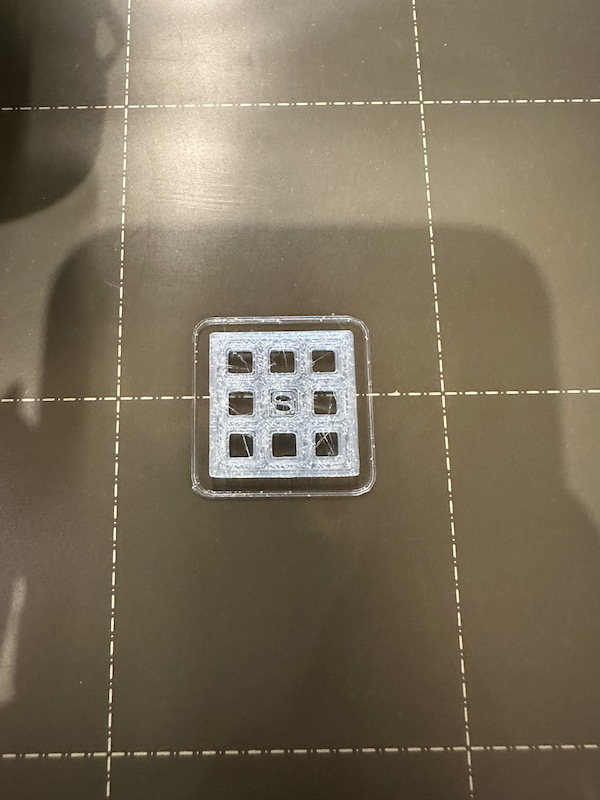
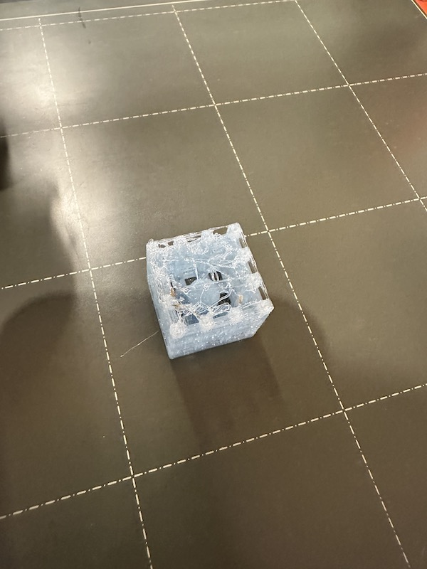
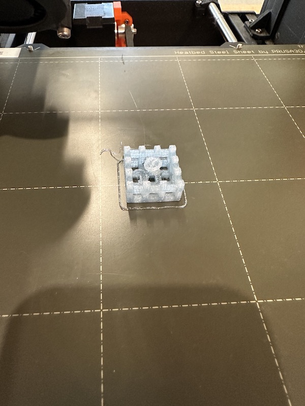
Resuming the failed print maybe wasnt the best idea, so I started over with a new design that excluded the middle sphere. I also added a brim to the design so that it would not move on the hot bed again. I made this change in Fusion 360, exported to PrusaSlicer, exported to the SD card, then began the print. A third of the way through the print, I paused the process, added the marble, then resumed the print. The original redesign of the top of the cube (solid bottom) printed successfully. Finally my design and print was successful.
The final print