Embedded Programming
This week I worked with different microcontrollers. Using an Arduino Uno, I programmed the Adruino to send power to a breadboard with a to control a button and 3 LEDS. I also programmed the Arduino to communicate through the serial monitor according to what LED was currently lit.
Research
The Arduino Uno operates with an ATmega328P processor. This processor has the following qualities:
RISC architecture
Can process 8 bits at a time, but has 32K bytes of programmable flash memory
Fully static operation,which means that the microcontroller is not started from its own instance. SRAM means that the memory cannot be changed during operation, while DRAM allows the operations to be changed during usage. RAM memory means that data is only stored when there is power being supplied, while flash is the opposite.
16MIPS (million instructions per second) throughput at 16MHz
Operating voltage is 2.7V to 5.5V
Process
In a group of my peers, we were able to test programming an Arduino Uno as well as an EPS32-C3. I have worked with the Arduino Unos before, so I found the process pretty intuitive. I ended up chosing this microcontroller because of its pinout availability and my previous experience with it.
Last semester I worked with an Arduino Uno setup and had it interact with physical components by writing code in Arduino IDE. Therefore, I already had the software installed. There was some rustiness in how to properly setup the Arduino, so working through it was an important part of the process.
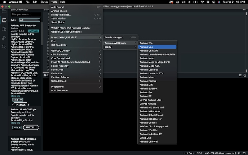
I connected the Arduino to my computer and opened up the Arduino IDE software. I then opened tools in the taskbar to select the board, Arduino Uno. Next step was to select the port, which was also in the tools taskbar, and since I work on a Mac, the correct selection was /dev/cu.usbmodem14101.
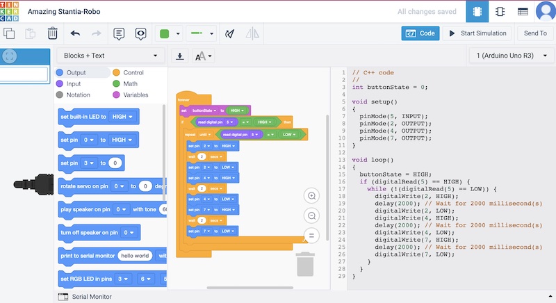
As for the code, I used TinkerCAD to practice making code because it is an easier workspace than doing it physically, seeing as I can make the setup virtually and change out materials. It also simplifies code by disquising it underneath buttons that are interchangable. Once I formed the code using the buttons I am able to translate it to C++.
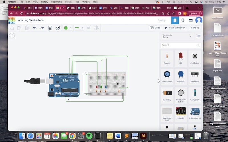
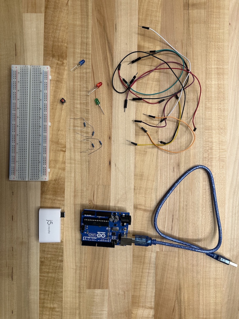
I set up the Arduino, breadboard, wires, button, resistors, and LEDs the same way I had in TinkerCAD.
I then copy and pasted the code from TinkerCAD into Arduino IDE and uploaded it to the Arduino. I tested the button and am happy to report that it worked. Here is the code that I wrote using TinkerCAD.
// C++ code
//
int buttonState = 0;

void setup()
{
  pinMode(5, INPUT);
  pinMode(2, OUTPUT);
  pinMode(4, OUTPUT);
  pinMode(7, OUTPUT);
}

void loop()
{
  buttonState = HIGH;
  if (digitalRead(5) == HIGH) {
    while (!(digitalRead(5) == LOW)) {
      digitalWrite(2, HIGH);
      delay(2000); // Wait for 2000 millisecond(s)
      digitalWrite(2, LOW);
      digitalWrite(4, HIGH);
      delay(2000); // Wait for 2000 millisecond(s)
      digitalWrite(4, LOW);
      digitalWrite(7, HIGH);
      delay(2000); // Wait for 2000 millisecond(s)
      digitalWrite(7, LOW);
    }
  }
}
Now that I had the intercation with input/output requirement met, I focued on communication with the Arduino.
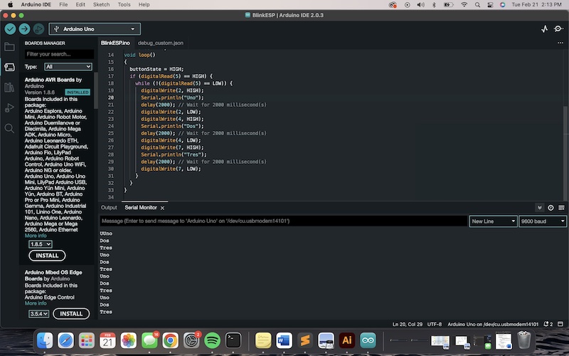
From the group portion of the assignment, which can be found HERE, I learned how to use serial commands to use the serial monitor. Using this knowledge, I wrote code that directed the Arduino to communicate "Uno," "Dos,"and "Tres," according to the corresponding light that power is being sent to. For example, when the first LED is lit for the 2000 milliseconds, the serial monitor reads "Uno," then when the second LED is lit, the serial monitor reads "Dos," and so on.
The commands that were added included the following:
Serial.begin(9600);
Serial.println("Uno")
Serial.println("Dos")
Serial.println("Tres")
The totality of the code with the addition of these new lines was as follows:
// C++ code
//
int buttonState = 0;

void setup()
{
  Serial.begin(9600);
  pinMode(5, INPUT);
  pinMode(2, OUTPUT);
  pinMode(4, OUTPUT);
  pinMode(7, OUTPUT);
}
int number = 0;
void loop()
{
  buttonState = HIGH;
  if (digitalRead(5) == HIGH) {
    while (!(digitalRead(5) == LOW)) {
      digitalWrite(2, HIGH);
      Serial.println("Uno");
      delay(2000); // Wait for 2000 millisecond(s)
      digitalWrite(2, LOW);
      digitalWrite(4, HIGH);
      Serial.println("Dos");
      delay(2000); // Wait for 2000 millisecond(s)
      digitalWrite(4, LOW);
      digitalWrite(7, HIGH);
      Serial.println("Tres");
      delay(2000); // Wait for 2000 millisecond(s)
      digitalWrite(7, LOW);
    }
  }
}
I uploaded the code to the Arduino, and to my delightful surprise when I pressed the button on the breadboard, the serial monitor read "Uno,"" Dos,"" Tres," as the LEDs lit up.