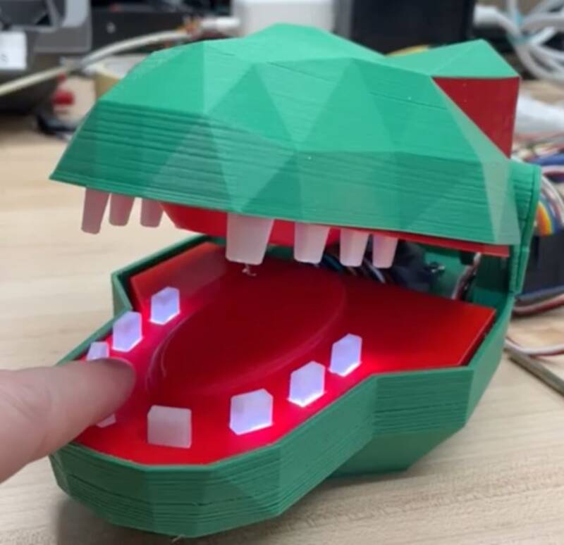
For this project, we decided to make a version of the child's game “Crocodile Dentist” Essentially, the idea of the game is to press down on the teeth of a plastic crocodile. One of these teeth will randomly cause the crocodile to snap its jaw shut. We ended up making an electromechanical version of this, but instead of a crocodile, we designed a low-poly style dinosaur.
We wanted our design to have more dramatic tension and strategic thinking than the purely mechanical toy. Since the jaw opens a bit more every time you press the button, you know when you're close to being "bitten". And we intended to have each tooth glow a different brightness, indicating roughly how far the jaw will advance when you press it.
Our design is controlled by an Arduino Uno which actuates a standard hobby servo. A custom-milled circuit board contains buttons and LEDs, and sits under the teeth.
Our design achieves:
mechanism: the jaw opens and closes. Also, we use complaint mechanisms to hold the teeth while allowing them to move, so the lower teeth can act as buttons and the upper ones are springy so they they don't hurt when they hit your hand
actuation: the jaw is operated by a servo. A one-way pawl system allows the microcontroller to "reset" the game after the jaw has dropped.
automation: the microcontroller manages the position of the jaw, and responds to someone pressing the teeth only once. It also provides user feedback by turning the tooth lights off once they've been pressed.
application: well, it's not going to change the world, but it's a fun toy.
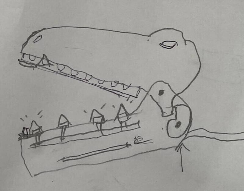
Here's a very early design sketch, showing the overall layout and concept. This drawing shows a "snail gear" actuation system that we didn't end up using.
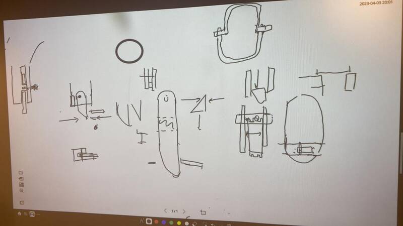
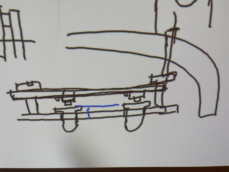
Here's a whiteboard jam session where we designed the pawl mechanism that opens the jaw, the servo mounting plan, and the overall head hinge mechanism.
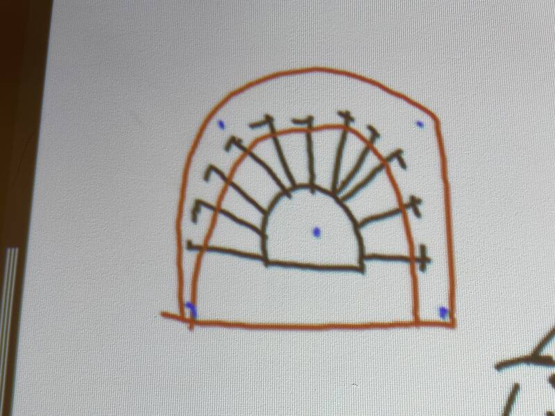
Design sketch of the teeth, and how the circuit board will carry the buttons and switches underneath them.
An early modeling design of the "tooth spider", a compliant mechanism to hold the teeth and let them move. This idea was borrowed from the commercial crocodile dentist toy.
A key idea with our design is that the servo horn pushes against a pawl attached to the upper jaw, holding it open. When the jaw has opened wide enough, the servo arm slips under the pawl, so the jaw falls shut suddenly. The pawl acts as a "one way gate", allowing for the servo to push the pawl to open the jaw, but when the servo needs to move back to reset its position, the pawl swings out of the way.
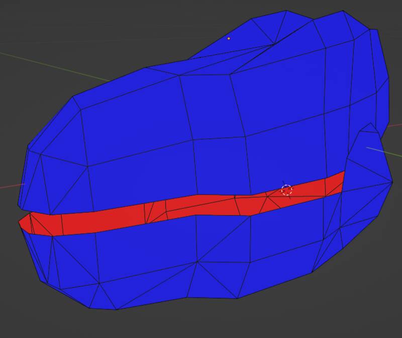
The head is designed using Blender, which is ideal for this sort of organic low-poly design. Once the polygon-wrangling was done, we imported the Blender surface into Fusion 360 to give it thickness and add mechanical components.
Outer surface of head, modeled in Blender and ready to import into Fusion 360.
An early modeling design of the opening mechanism. The servo is at the bottom, the horn that pushes on the pawl is not shown.
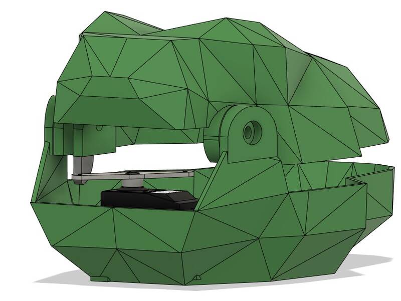
A more complete design: the Blender surface has been thickened into a shell, and the hinge and servo mechanisms are shown.
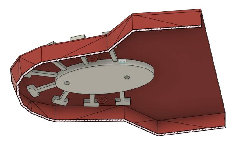
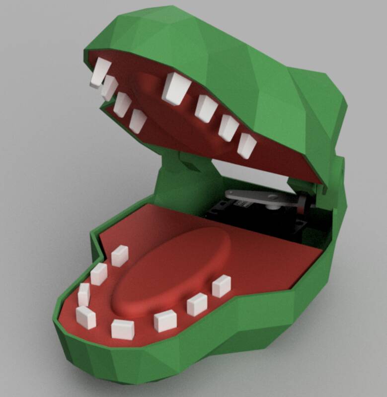
A cutaway view of the lower jaw piece. The teeth are mounted to a central "spider", which acts as a compliant mechanism to hold the teeth in place while allowing them to move. We borrowed this idea from the commercial Crocodile Dentist toy. The upper teeth are also mounted on a compliant "spider" so they don't hurt your fingers when they slam down.
A rendering of the final CAD design.
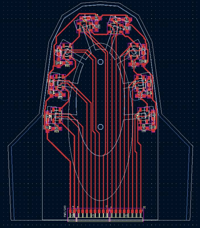
Since we have to manage 8 buttons and 8 LEDs, and since the buttons have to be securely mounted beneath the teeth, we milled a custom circuit board to carry these parts. (We didn't mill our own microcontroller: we used an Arduino Uno. The Xiao boards have too few pins, and we didn't have time to solve that problem in a clever way.)
Designing the PCB in KiCAD. We imported a DXF from Fusion showing the shape of the head and the position of the teeth, so we could design the board to fit in the head, with buttons and lights under the teeth.
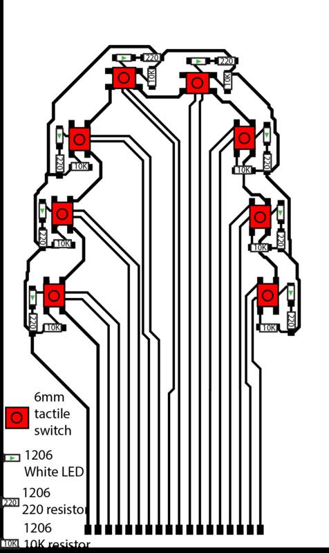
A soldering guide our board designer made. When someone else is doing the soldering, guides like this really help!
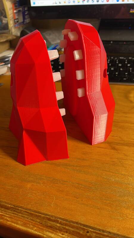
Finished 3-d printing the internal mouth pieces. The compliant "teeth spiders" are held in place by hidden screws. Most of the parts are printed in PLA, but the teeth are printed out of translucent white PETG, so the LEDs glow through them and the compliant mechanism is more flexible.
Milling the PCB. We accidentally had the outline cut inverted, so it cut inside the boundary rather than outside, so we had to repair a few traces very close to the edge.
Soldering the PCB. We had to solder the header pins directly to the traces rather than the solder pads to make room for the wiring.
This side view of the completed model shows a few things. First, the eyes are made of adhesive vinyl. (Thanks to Dara for the eye design idea!). Second, you can see the terrible print quality in the hinge caused by a malfunctioning 3-d printer. This made this area too weak to support the loads on it. You can also see a 3-d printed brace, which was glued on below the jaw hinge to strengthen it.
Testing the code before installing the electrical components. Note how the servo moves with each button press.
Play-testing is as important as code-testing! In this early test, Bella has to hold the back of the head to keep it from flexing, which would cause the upper jaw to slip past the servo horn and fall. We later modified this to make it much stronger.
First, we didn't think carefully enough about the structural strength of the outer shell: the thin "cheeks" weren't strong enough to support the jaw hinge, and the servo mount couldn't withstand the torque placed on it.
Our lab has had tons of problems with our printers lately, and we had very poor layer adhesion when printing our design, which made the model even weaker than we designed it.
We solved these first two problems by building several reinforcing pieces, which we glued on to the frame to make it more rigid.
The weak frame meant that the servo horn didn't always engage with the opening pawl every time, and sometimes slipped when we didn't want it to. Strengthening the overall design improved this problem, but some fine adjustment is needed.
To really fix these problems, we need to print another lower jaw, but we ran out of time.
Another minor problem was that we didn't include the circuit board as a modeled component in our CAD design. As a result, it didn't quite fit into the mouth piece, and the header wires bumped into the servo. We solved the first roblem with a Dremel, and solved the second problem by soldering the header directly to the traces rather than the solder pads.
There were also a few elements of our intended design that we didn't get to complete before time ran out. In particular, we wanted the buttons to advance the servo by a random amount: teeth that would move the servo farther would glow brighter. You'd think this would be an easy modification to the code, but since an Arduino Uno only has 6 PWM pins, varying the brightness of 8 LEDs was a tricky problem we didn't have time to solve.