4. Embedded Programming
The assignment this week is to familiarise ourselves with two differernt microcontrollers, compare them, and chose one to use in our personal projects.
Background
Our group had all previously used Arduinos before so we were comfortable with the software and had the IDE downloaded.
Arduino:
Our group already had the Arduino IDE installed, and so we started off by downloading a premade blink sketch provided by our instructor.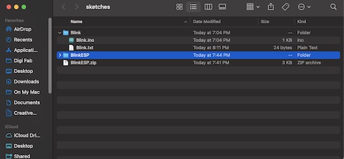
      // the setup function runs once when you press reset or power the board
      void setup() {
        // initialize digital pin LED_BUILTIN as an output.
        pinMode(LED_BUILTIN, OUTPUT);
      }

      // the loop function runs over and over again forever
      void loop() {
        digitalWrite(LED_BUILTIN, HIGH);   // turn the LED on (HIGH is the voltage level)
        delay(1000);                       // wait for a second
        digitalWrite(LED_BUILTIN, LOW);    // turn the LED off by making the voltage LOW
        delay(1000);                       // wait for a second
      }
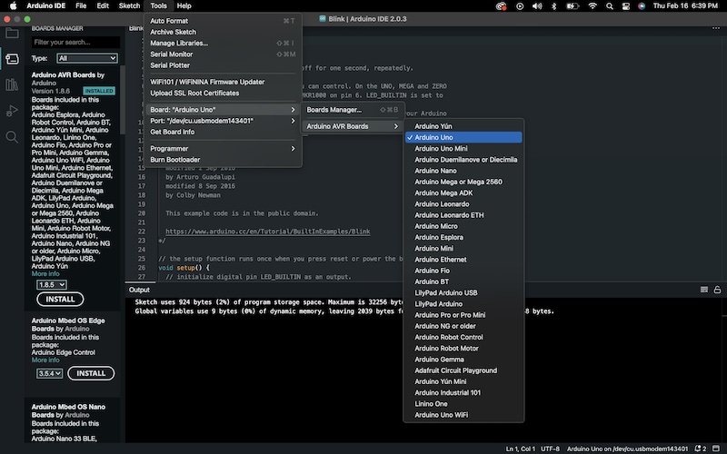
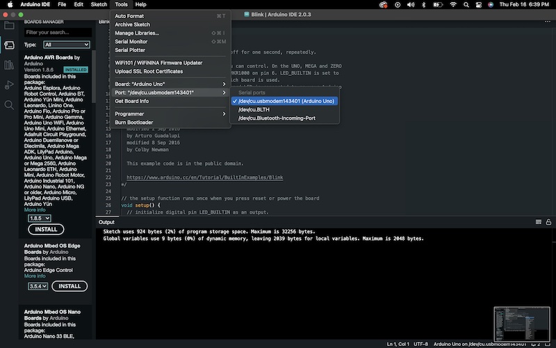
Once we had the code, we connected to the arduino using [tools > port > arduino uno] and [tools > port] to set the port to use for the arduino.
Once we had the arduino connected we ran the program and the built in light on the board blinked as expected.
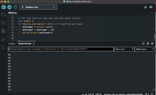
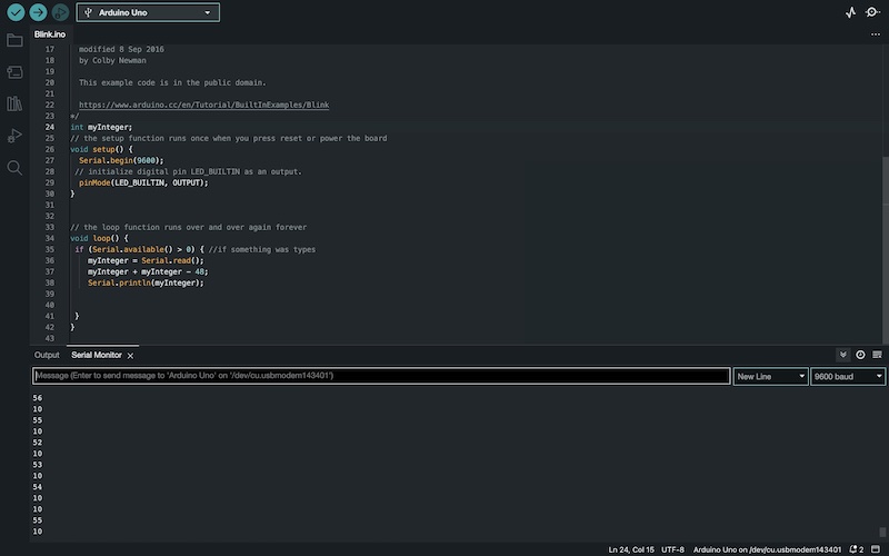
We then experimented with the serial monitor and individually came up with a couple programs that could turn the light on or off using the serial monitor.
This code seemed to detect the serial inputs correctly, but wasn’t producing the desired outputs on the board.
      Char input;

      void setup() {
          Serial.begin(9600);
          delay(2000);
          pinMode(LED_BUILTIN,OUTPUT);
          Serial.println("Type 1 to turn light on or 0 to turn it off.");
      }

      void loop() {
          if(Serial.available()){
              input = Serial.read();
              Serial.println(input);
              if (input=='1'){
                digitalWrite(LED_BUILTIN,HIGH);
                Serial.println("1");
              }
              if (input=='0'){
                digitalWrite(LED_BUILTIN,LOW);
                Serial.println("0");
              }
          }
      }
With some modifications the code was able to turn the light on or off with the serial port correctly.
      int myInteger;
      // the setup function runs once when you press reset or power the board
      void setup() {
          Serial.begin(9600);
          delay(2000);
          pinMode(LED_BUILTIN,OUTPUT);
          Serial.println("Type 1 to turn light on or 0 to turn it off.");
      }

      void loop() {
        if (Serial.available() > 0) { // if something was typed
          myInteger = Serial.read(); // read the input
          Serial.println(myInteger); // print the result
          myInteger = myInteger - 48;
        }
        if (myInteger == 1){
          digitalWrite(LED_BUILTIN, HIGH);
        }
        else if (myInteger == 0) {
          digitalWrite(LED_BUILTIN, LOW);
        }
      }
We used this example to understand how serial communication works with arduino.
      int myInteger; // initialize the variable

      void setup() {
        Serial.begin(9600); // initialize the serial monitor
      }

      void loop() {
        if (Serial.available() > 0) { // if something was typed
          myInteger = Serial.read(); // read the input
          myInteger = myInteger – 48; // subtract 48 for int value
          Serial.println(myInteger); // print the result
        }
      }
ESP3:
After we got the arduino board working we moved onto a different board, the ESP32-C3.
Since this board wasn’t included in the arduino IDE by default, we installed the board package to be able to connect to the board. This is done with [file > preferences], and then pasting in the URL
https://raw.githubusercontent.com/espressif/arduino-esp32/gh-pages/package_esp32_dev_index.json
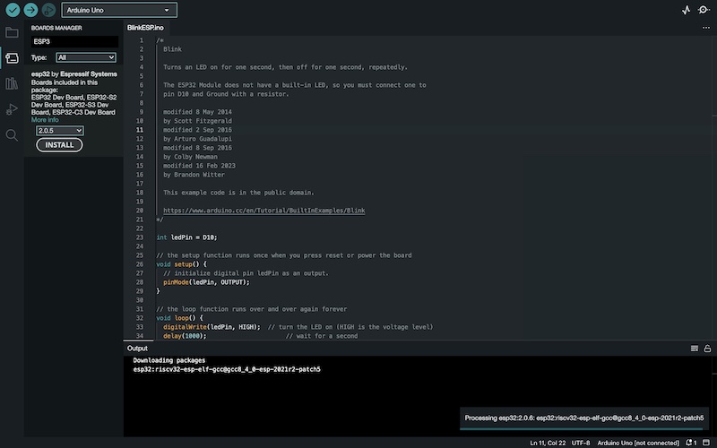
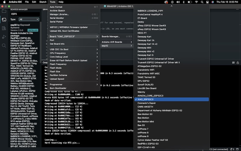
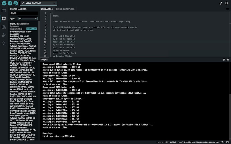
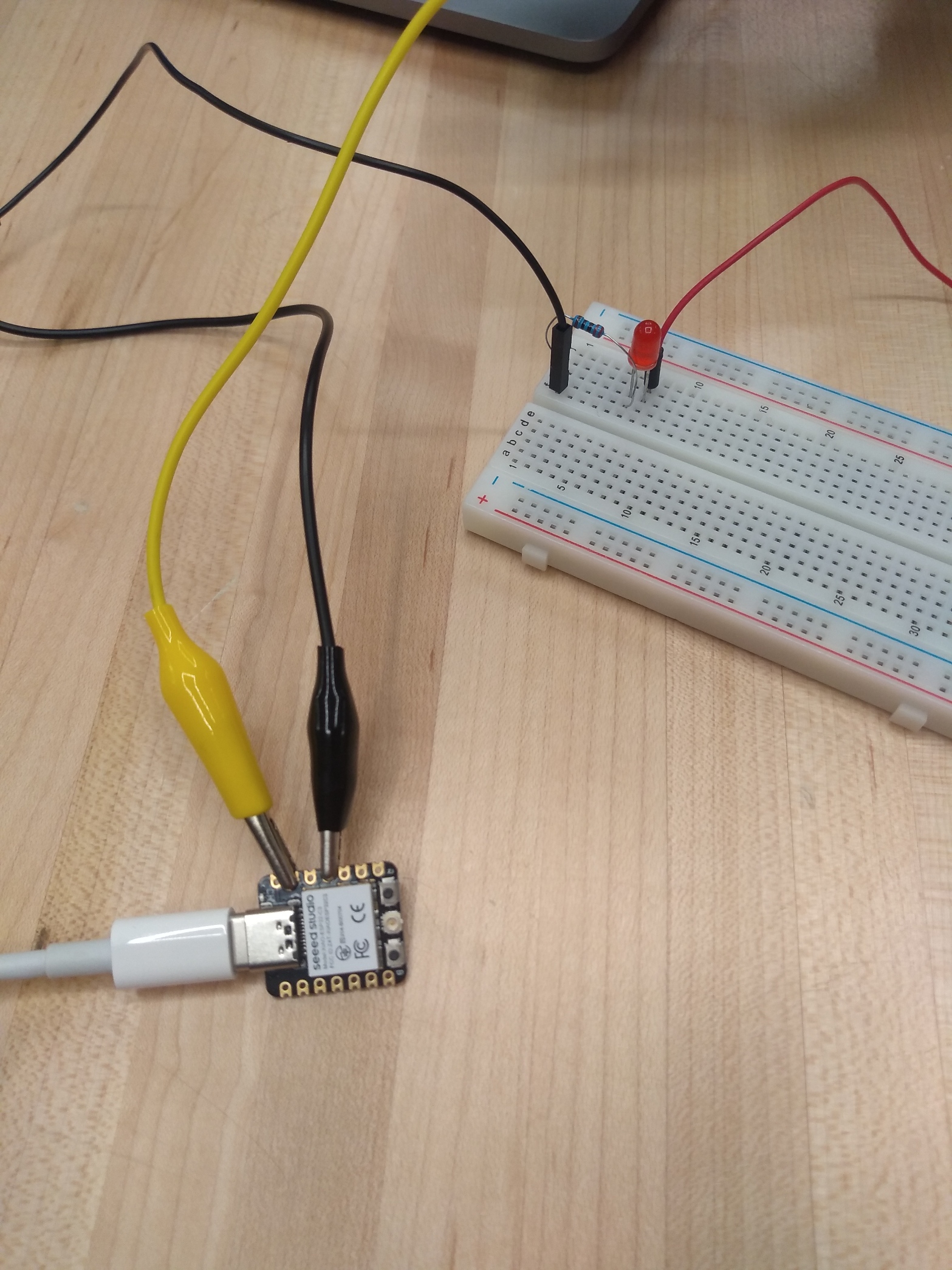
Then we went to [tools > board > boards manager] and then searched for the board and installed the package. Once the package was installed it could be connected using the same method as with the arduino. [tools > port > ESP32 Arduino] We then downloaded a program for blinking a light with the ESP32. We then connected the pins called in the program to a breadboard to make an Led blink.
Choosing the board:
Final code and blinking lights:
Data:
ESP32-C3 specs:
Arduino/ATmega328:
RISC architecture
Can process 8 bits at a time, but has 32K bytes of programmable flash memory
Fully static operation,which means that the microcontroller is not started from its own instance. SRAM means that the memory cannot be changed during operation, while DRAM allows the operations to be changed during usage. RAM memory means that data is only stored when there is power being supplied, while flash is the opposite.
16MIPS (million instructions per second) throughput at 16MHz
Operating voltage is 2.7V to 5.5V
Useful links
-
https://docs.arduino.cc/resources/datasheets/A000066-datasheet.pdf
http://ww1.microchip.com/downloads/en/DeviceDoc/Atmel-7810-Automotive-Microcontrollers-ATmega328P_Datasheet.pdf