Week 6 group 2 documentation
Dan Collins
Wyatt Goldsmith
Zach Campbell
Multimeter
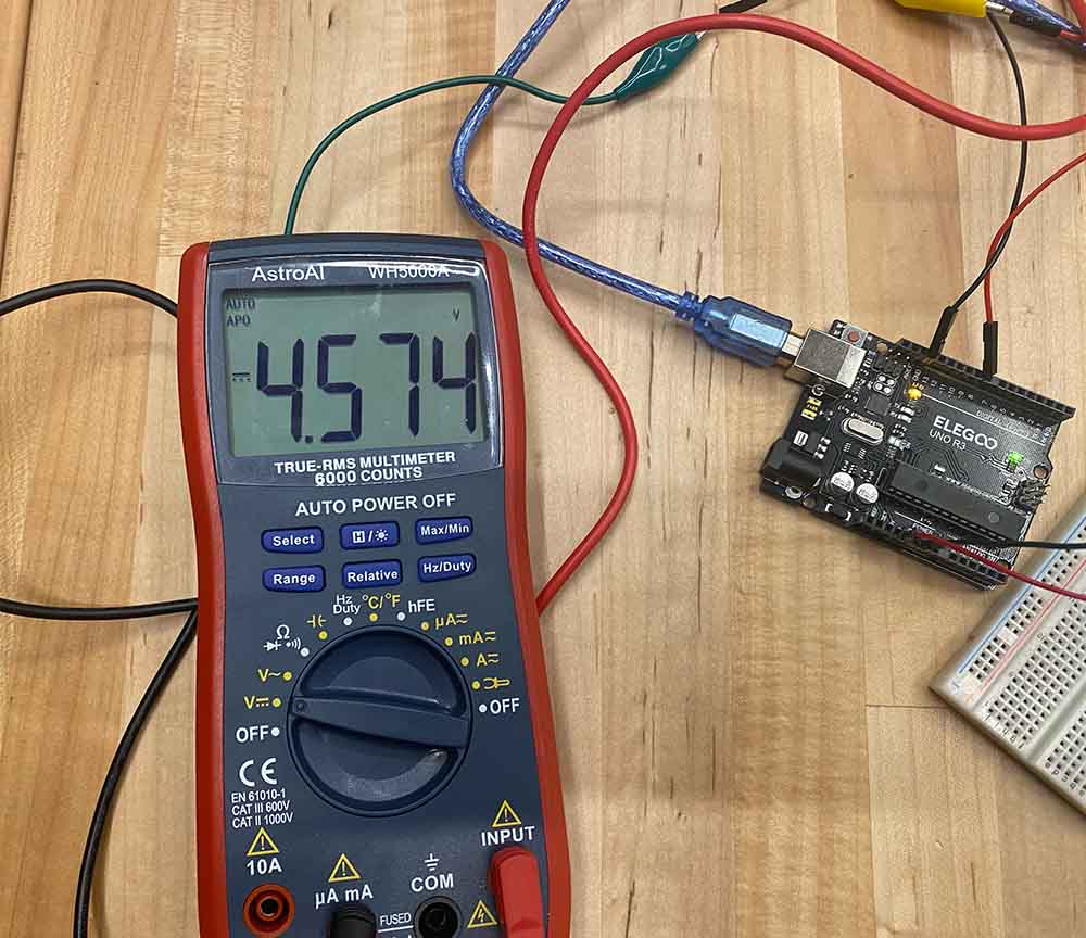
We used a multimeter to measure various parts of a simple circuit. The circuit contained an arduino powering an Led with a 220 ohm resistor.
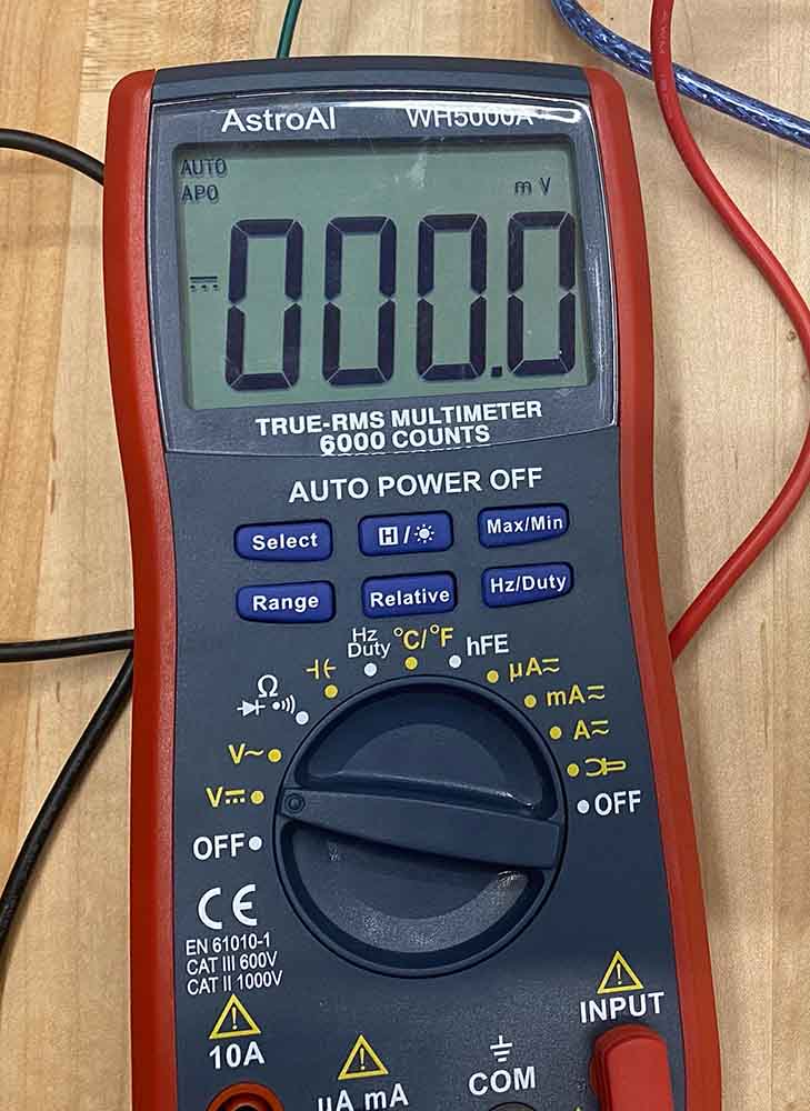
The first test we did was to measure the direct current voltage across the Led. The reading was 4.572 when the led was on, and 0 when off.
Next we measured the resistance of the resistor. The multimeter started screaming as soon as we set it to the 2000Ω resistance measuring setting, and stopped when we unplugged the wire at the bottom and plugged it into the resistance measuring port. The resistor measured 214 Ohms.
For the next step we measured the value across the resistor at 3.1 volts, and the value across the led at 1.8 volts. We then measured the voltage across both the resistor and Led to be 4.9 volts. We expected that these values would add up to equal their combined voltage. We found that the values roughly add together to equal a bit less than the total voltage from the 5V out pin to ground. That was because of the voltage drops within the wires.

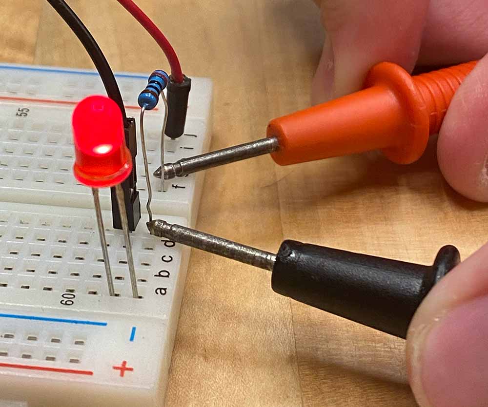
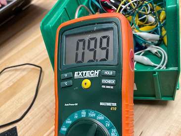
Finally we measured the current flowing through the circuit. Again we switched the port for the cable at the bottom, this time to 200mA. We changed the circuit so that the multimeter was required to complete the circuit, and measure a flow of 9.9 mA of current.
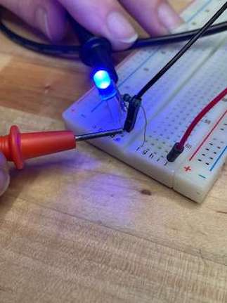
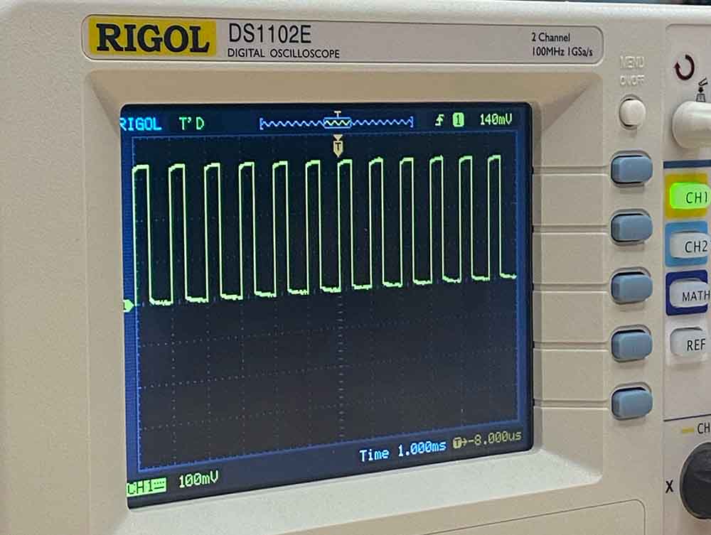
Osciliscope
We measured signals from a Xiao ESP32 - C3. First we made a program that turned a pin on or off every second,which resulted in a very long square wave.
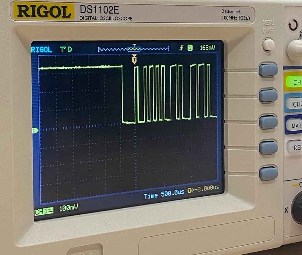
Next we changed the frequency and used the trigger to keep a steady view of the wave.
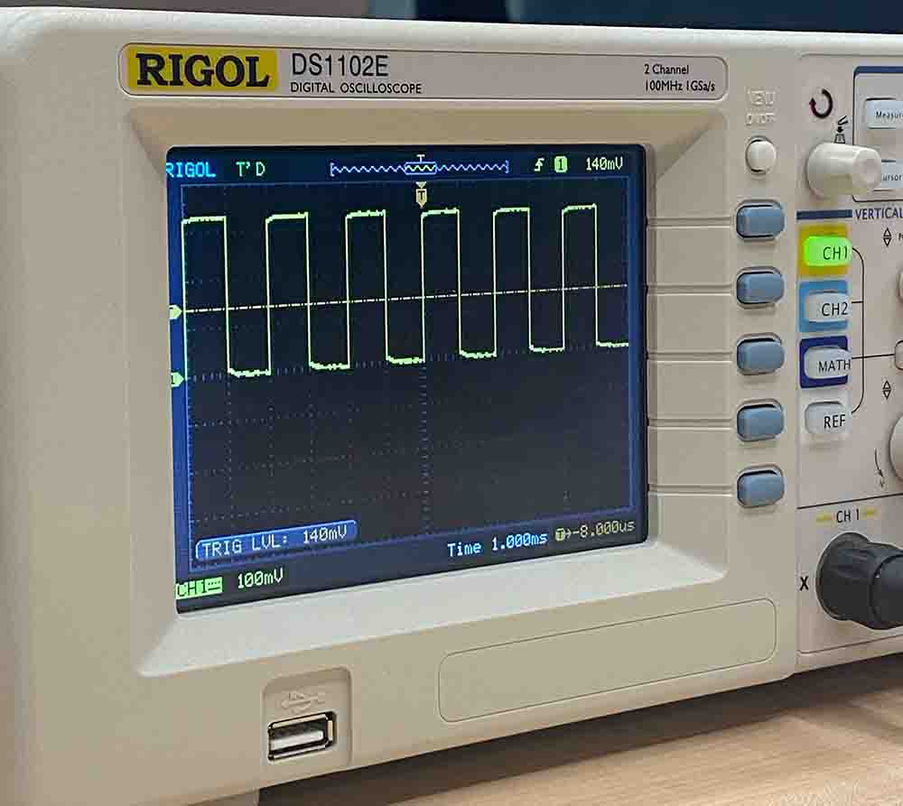
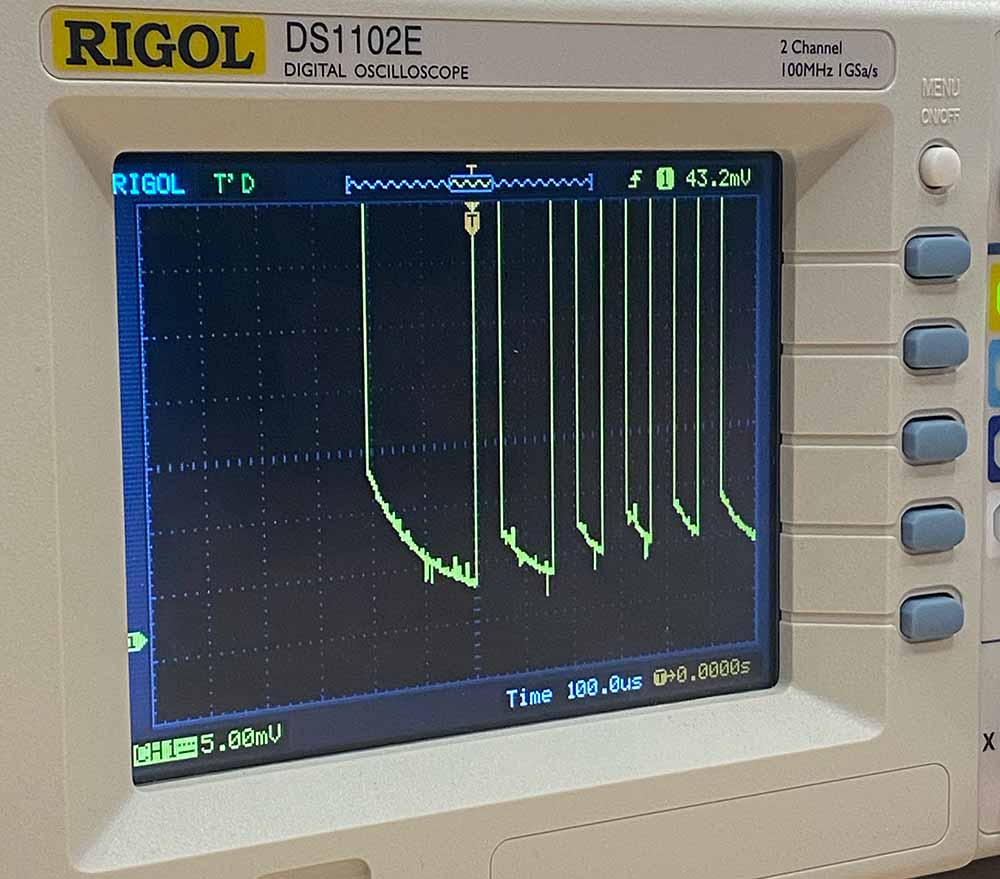
Finally we used the serial port to send the message “Hello world” to the chip and looked at the pattern of oscillations or 1s&0s that comprised the message. Zooming in, we could see the falloff curve from the capacitance in the wires.