Electronics Design
Group assignment:
&esmp;Use the test equipment in your lab to observe the operation of a microcontroller circuit board (as a minimum, you should demonstrate the use of a multimeter and oscilloscope)
Group Members:
Process
In this week’s lab, we learned Ohm’s Law, how resistors work, how to measure voltage, current, and resistance with a multimeter, how to tune an oscilloscope, and how to read an oscilloscope.
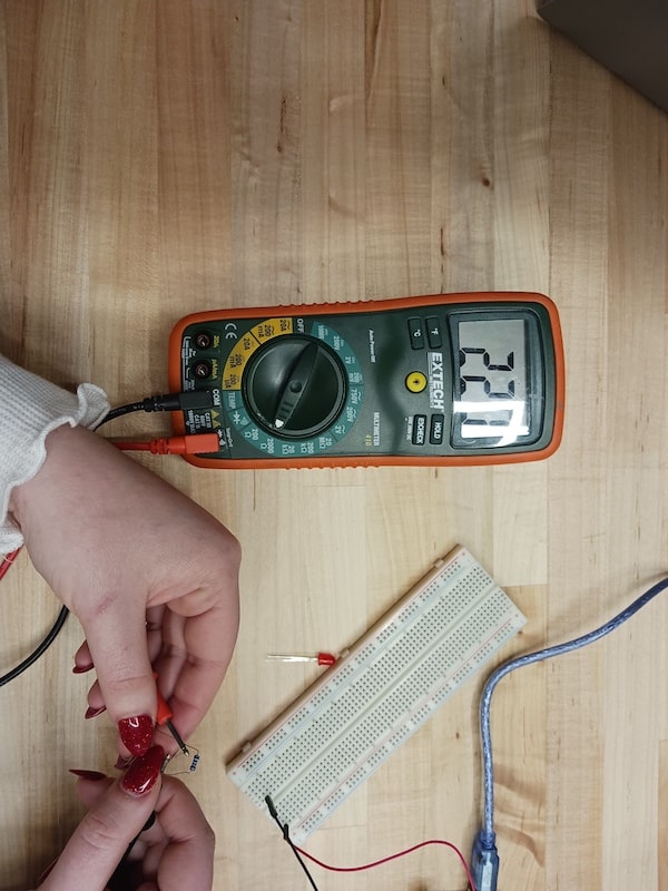
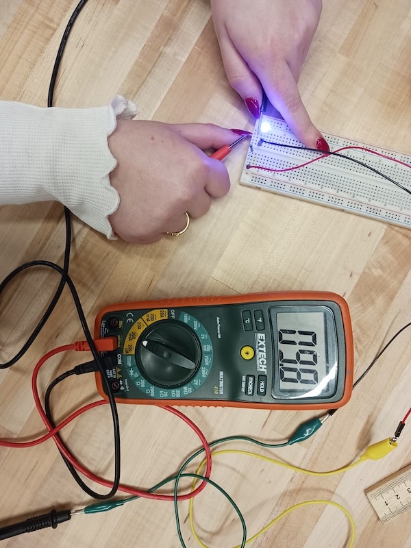
Our group,Evan, Dara, and Aziz, started working on the simple light and resistor circuit. With this circuit, we had to use a multimeter to determine the voltage when the light is on, the voltage when the light is off, the current type, the resistance, the full circuit voltage, and the overall current.
Multimeter
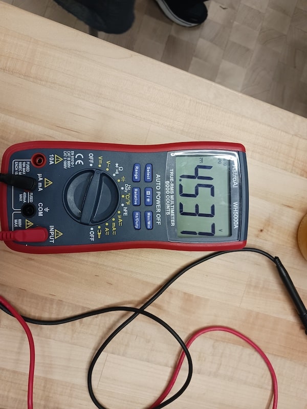
Using a multimeter, we were able to determine that the voltage or power being supplied to the LED was 4.537v DC power. DC means direct current or one that doesn’t alternate like with AC.
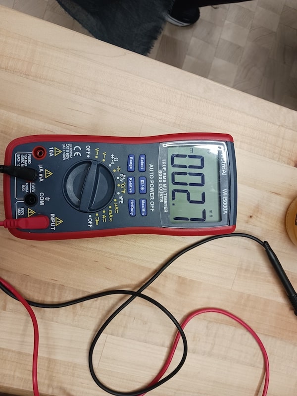
The value we recorded for when the LED was off was 0v DC. The value was zero because no power was being supplied to the LED.
We then used the multimeter to measure the resistance that the resistor was creating by attaching it to the resistor’s wires. The value we got for the resistance, measured in Ohms, was 220. To be able to read this amount of resistance we switched the multimeter to the 2000Ω setting.
After that, we measured the voltage throughout each individual component of the circuit. The voltage through the resistor was 2.7v, through the LED it was 1.8v, and through both, it was 4.8v.
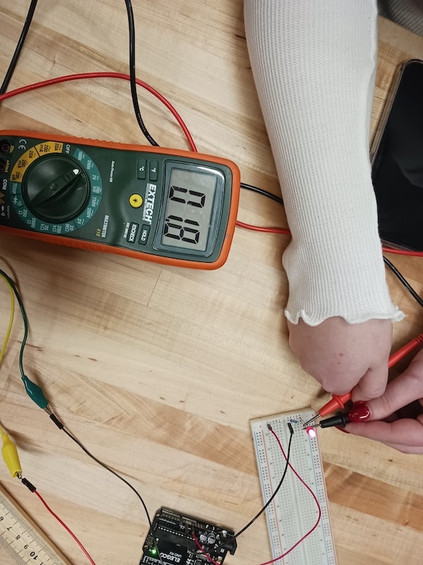
These values were not expected by our group because the loss of voltage through the components makes the measurement of the circuit 4.9v rather than 5v which was the value being supplied to the circuit.
Lastly, we measured the current through the circuit. The current through the entire circuit was 9.8mA(milliamps).
Oscilloscope
After we finished measuring the voltage, resistance, and current of the first circuit we moved on to the second which was an ESP3 microcontroller hooked up to a pc running the Arduino IDE as well as an LED and resistor.
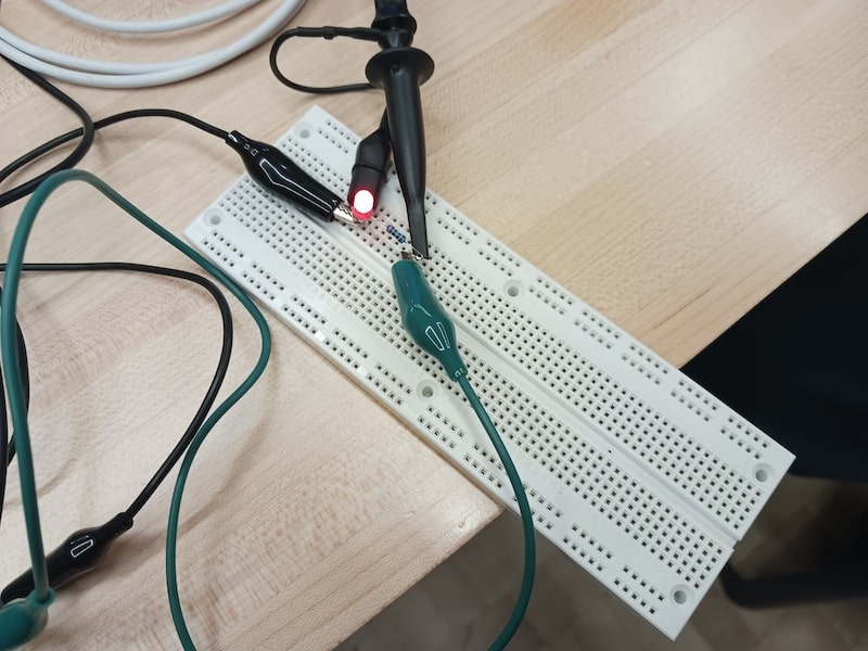
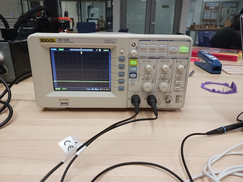
The first thing we did with the Oscilloscope was calibrate the display. We did this by hooking one of the input wires onto the test connection and turning the time frequency dial. We did this until the image on the Oscilloscope changed from a yellow bar to multiple square waves.
We then attached the hook wire to the ESP3 circuit and tested it with an on/off delay of 1 second, always on, and the binary code for the word “Hello”.
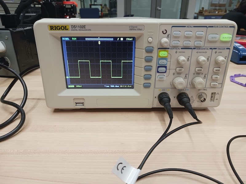
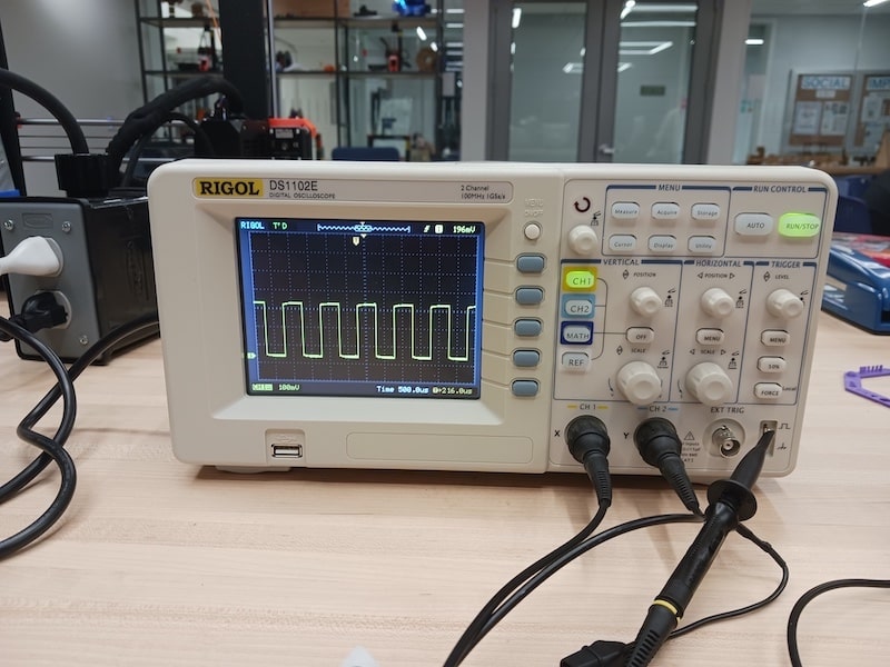
With a one second time delay the square waves were very large, each plateau of the line equating to full or no power being transferred to the light.
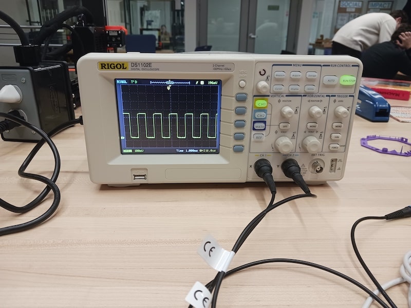
Next, we set the light to always be on and the yellow bar across the screen returned. We carefully focused the timeframe to be 1.0 milliseconds and were able to see the square waves again. This means that even when a light is “on” it is actually still alternating between on and off but it is so fast that our eyes and brains cannot perceive it as turning off at all.
Lastly, using the serial monitor we were able to send over the binary code for the word “Hello” to the light. With this every 1 was converted to full power and every 0 was no power. The light stayed on for a few seconds and even flickered as it went through the entire code for it. On the Oscilloscope we got to see unique peaks and valleys with the smallest ones being a second long or one digit in the entire code.