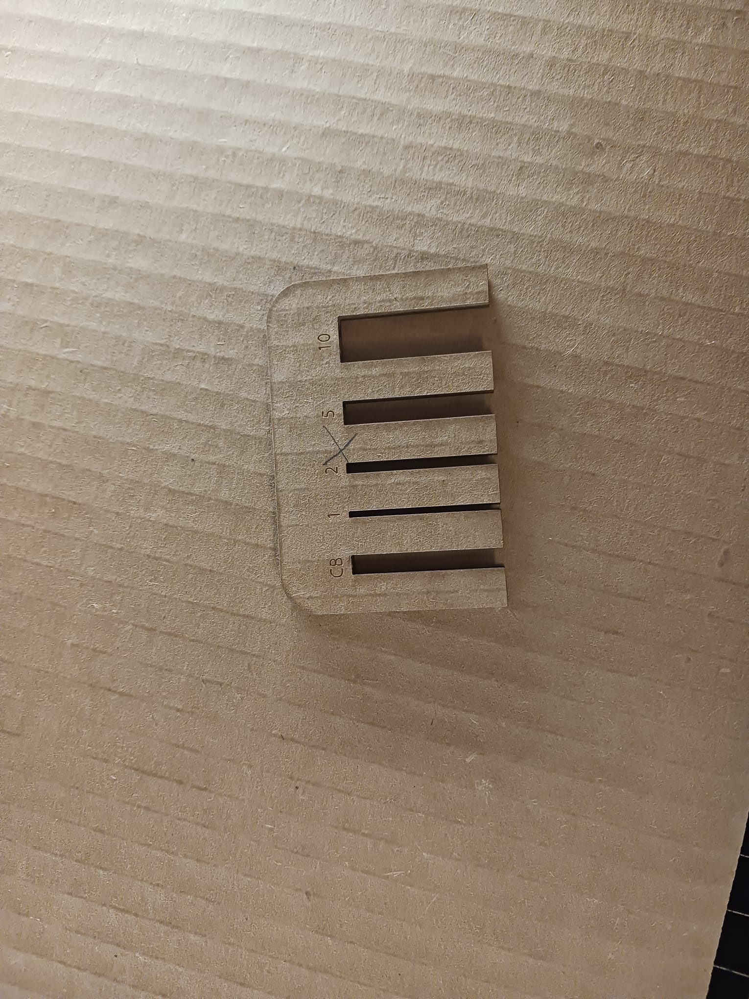
As we wanted to measure the kerf, we used a Fushion 360 design of a comb with teeth aligned at different distances(as shown in the photo). The purpose of this was to enable us to take the average of different widths so that we get a more a accurate kerf approximation. The gap widths were 3.9 mm(the thickness of the cardboard we cut), 1 mm, 2 mm, 5 mm, and 10 mm. First, as the design was 3d, we needed a 2d projection of it. So we clicked on Proejct/Include and then project under the create Tab. We then rightcklicked on the resulting 2d sketch, clicked export and then selected DXF format as we have to open the file in Adobe Illustrator to send it to the Epilog software.
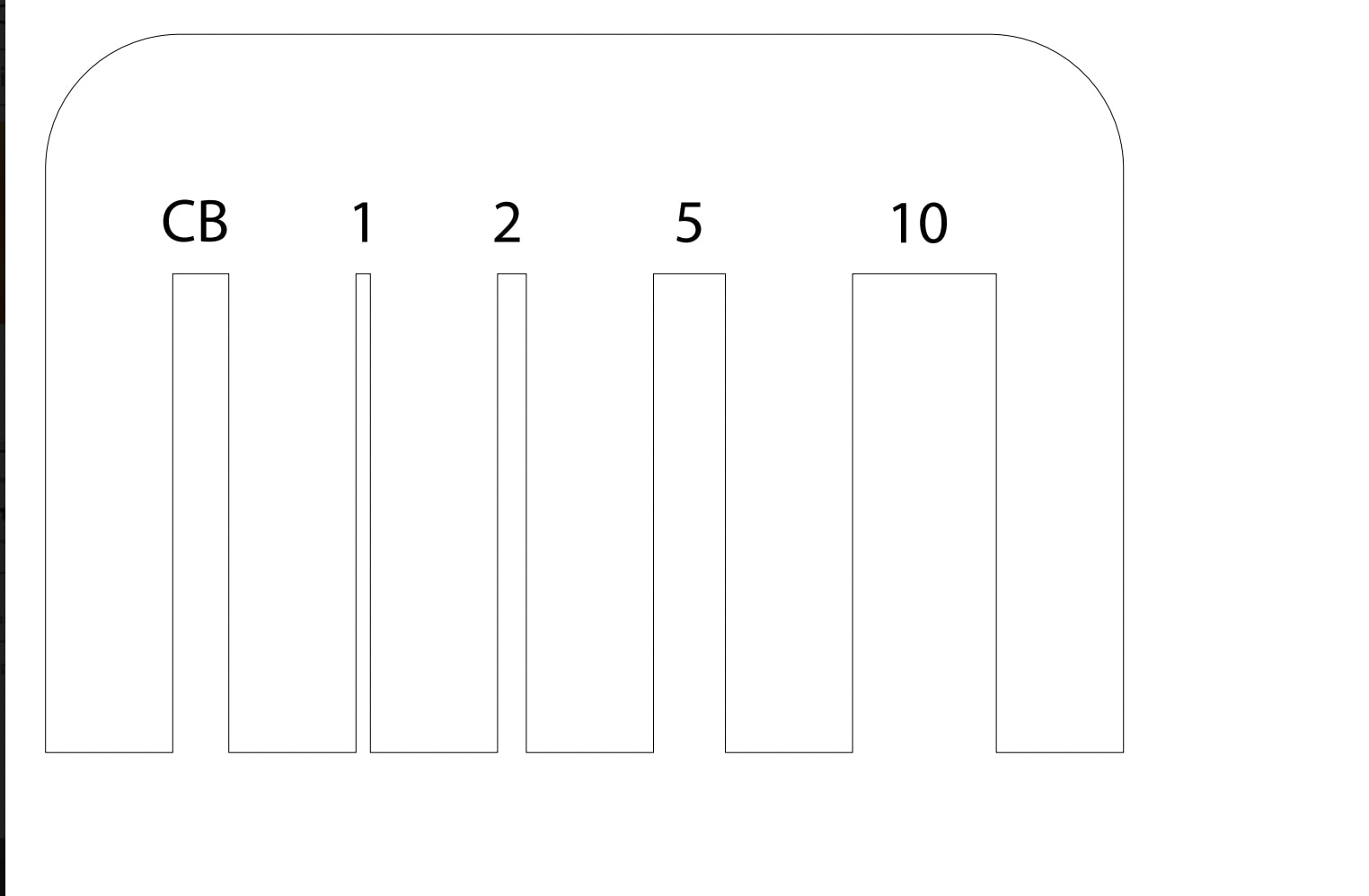
We opened the file in Adobe Illustrator. Before sending it to Epilog, we had to do two things. First we wrote, using the text tool in Adobe, the width of each gap above it to be engraved at the comb. Then, we highlighted the whole design and went to Appearance at the right side and changed Stroke width to 0.01 mm as the Epilog software vector-cuts any line this thin or thinner.
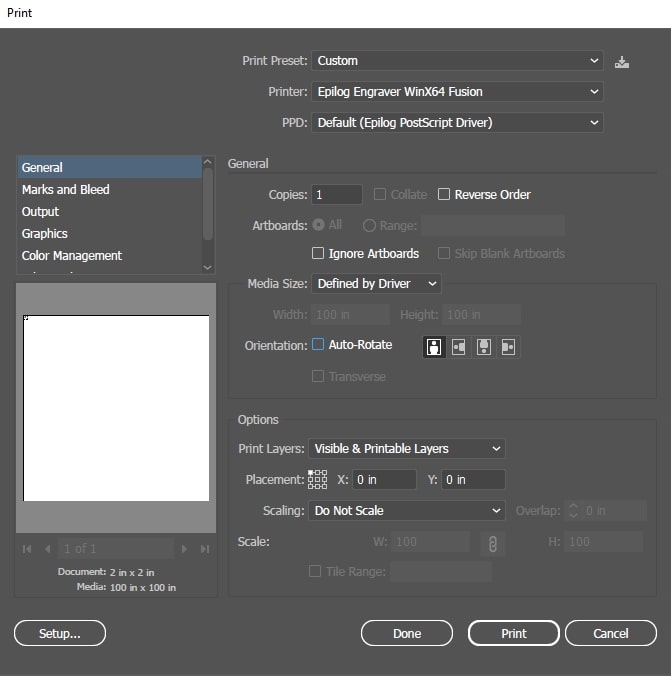
As all is done on Illustrator, we clicked on print which automatically printed the file to the Epilog Software. The Epilog software is responsible of sending the design to the laser cutter directly. In the Settings, we had to select Epilog Engraver as the Printer and change sclaing to Do Not Scale as we already did the sclaing in Fushion and Illustrator.
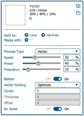
In the Epilog Dashboard, we had to change three variables:
These variables differ based on the material and other factors. In our case, we set the engrave variables to 75%, and 25%, 50% for speed, power, and frequency, respecively. For the vector-cut properties, we used 30%, 40%, and 10%. And within the dasboard, we turned on the Air Assist. Now, we are ready to click print and got ot the next stage.

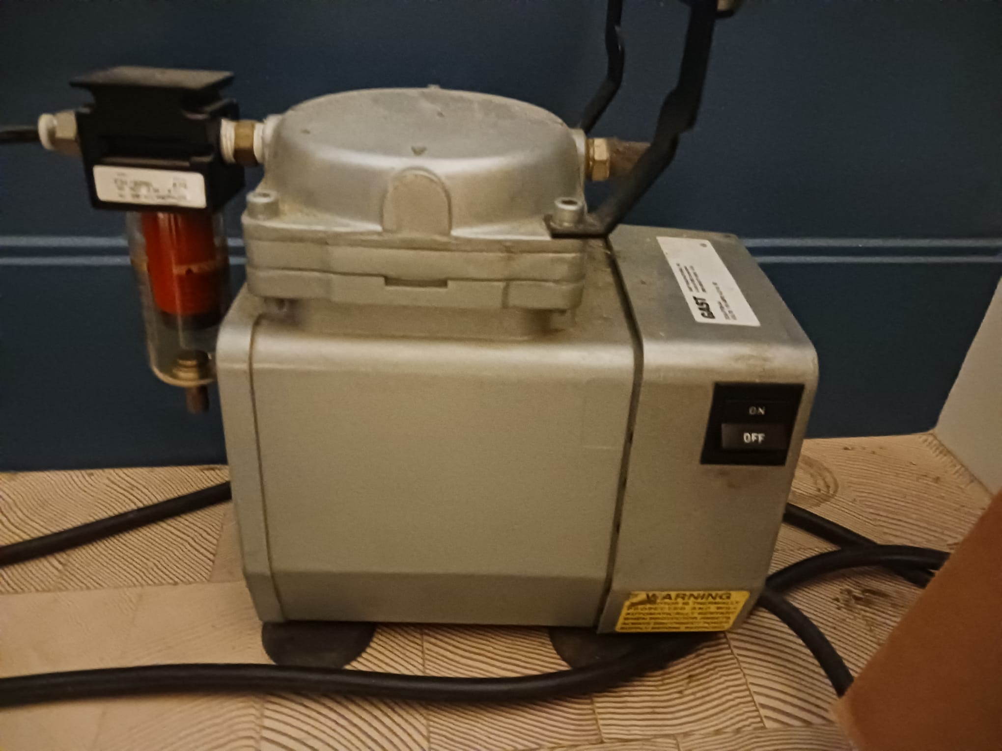
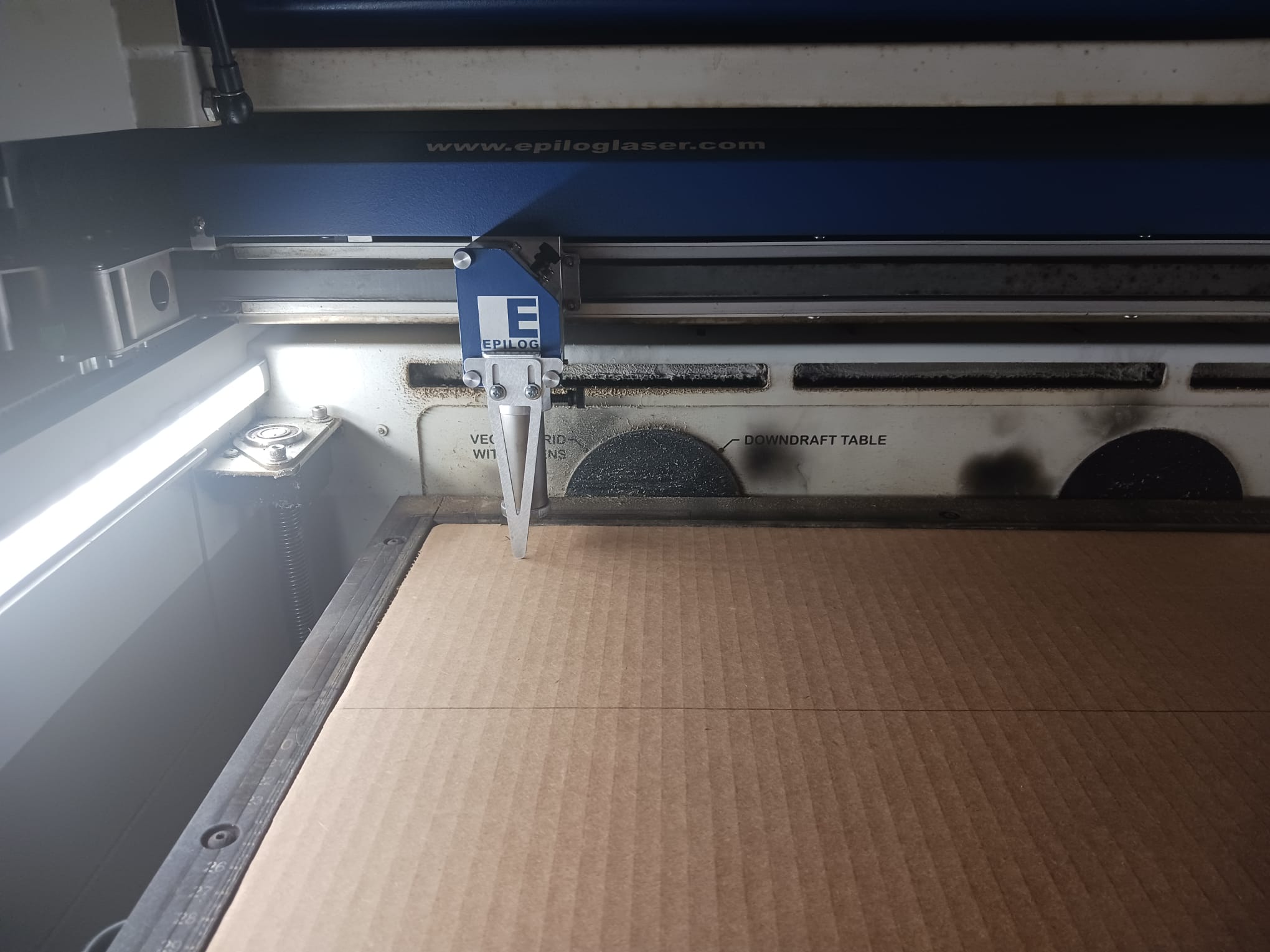
First, we turned on the machine and the ventilation system in the building to make sure toxic gasses are cleared away. We also turned on the Air Assist to help the machine blow away smoke from the laser path.
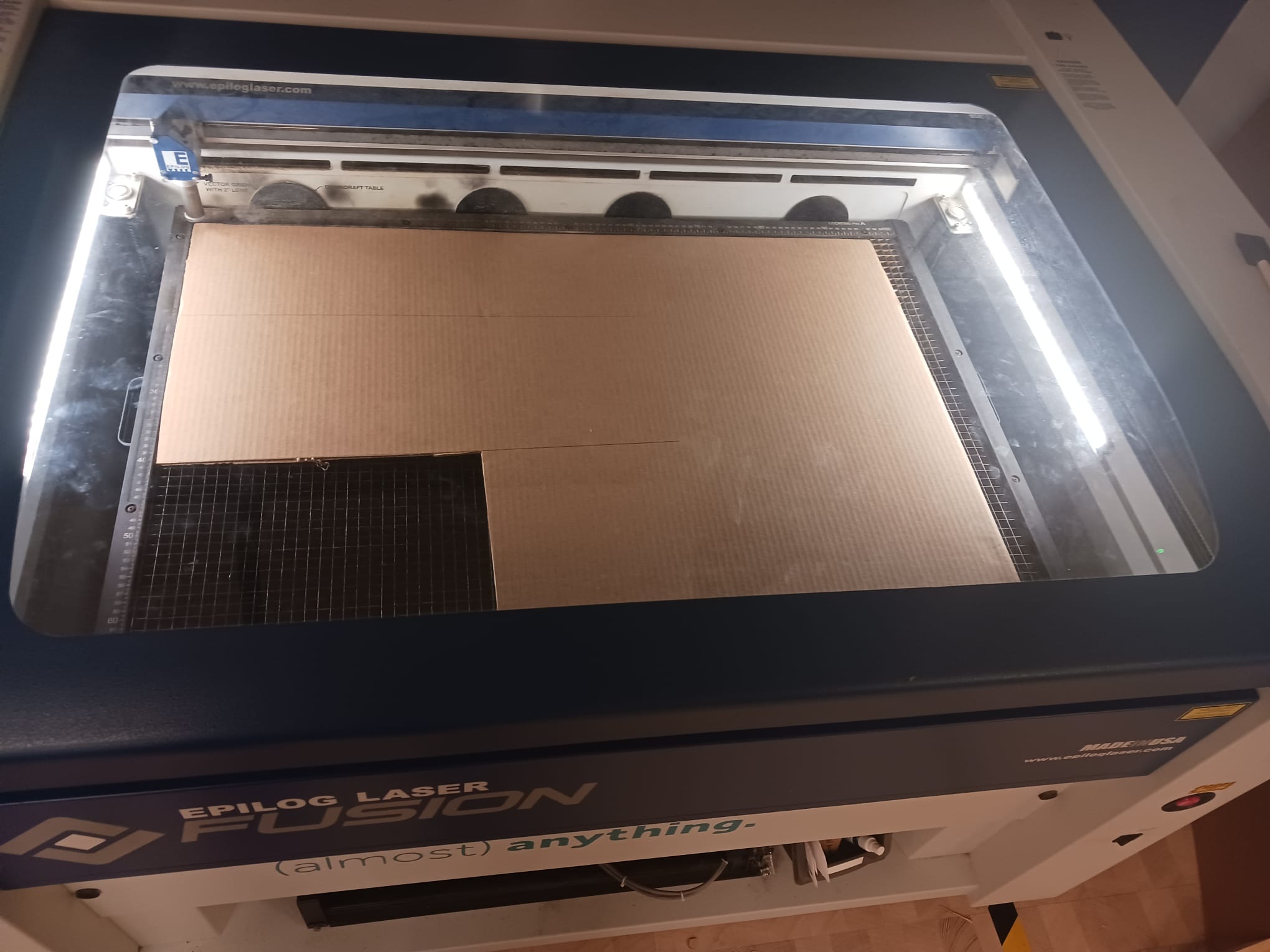
Next, on the settings on the machine itself, we had to change the focus, which is the height of the bed. We moved the joystick until the bed hit the focus beam triangle. We then navigated to jog to move the beam to the top left corner to make sure the board is not cut in the middle. By pressing the joystick both after focus and jog, we set the position of the beam and the bed. We then closed the laser cutter and were ready to press Go.
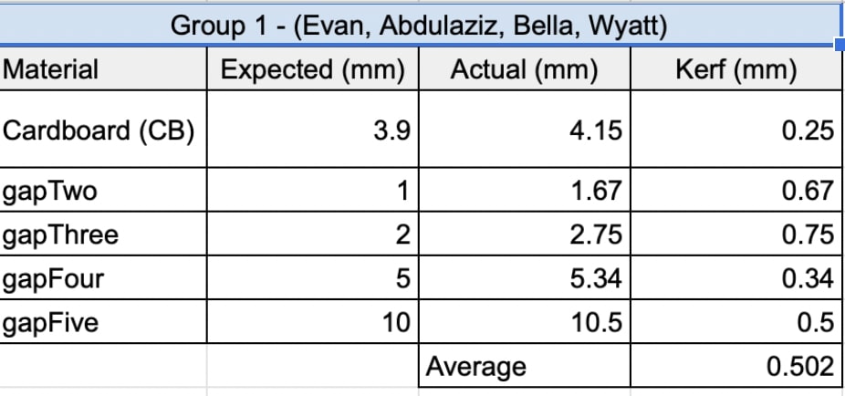
As soon as the comb was cut, we measured the actual gaps and compared them to those in our design, with the kerf representing the difference between actual and expcted. Then, we calculated the average kerf and got 0.502 mm, which means we have to take this into account for future cuts.