Lecture Composites
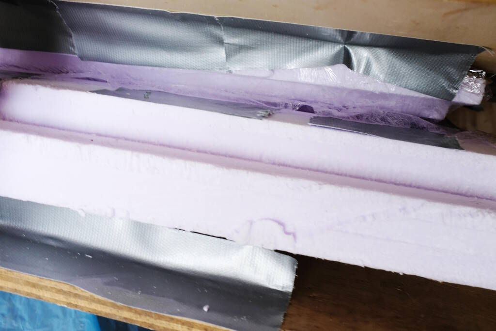
I will focus on composites in this week. Saco gave us some insight in his process making the tyres of his motorcycle, explaining the foam mold and how he got the rubber into the mold:
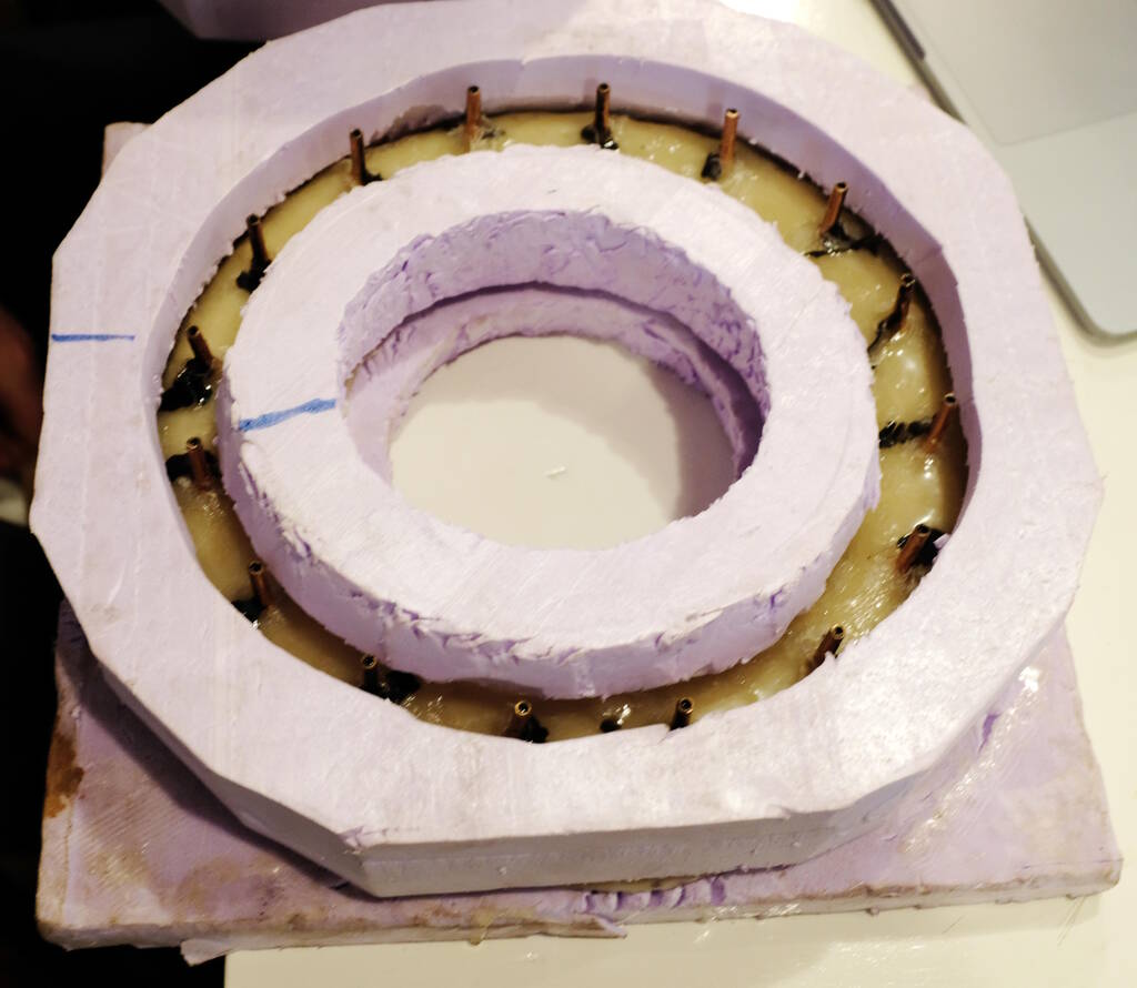
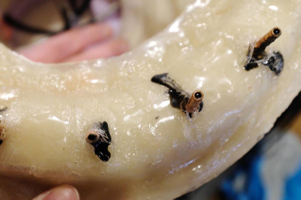
The tubes going in:
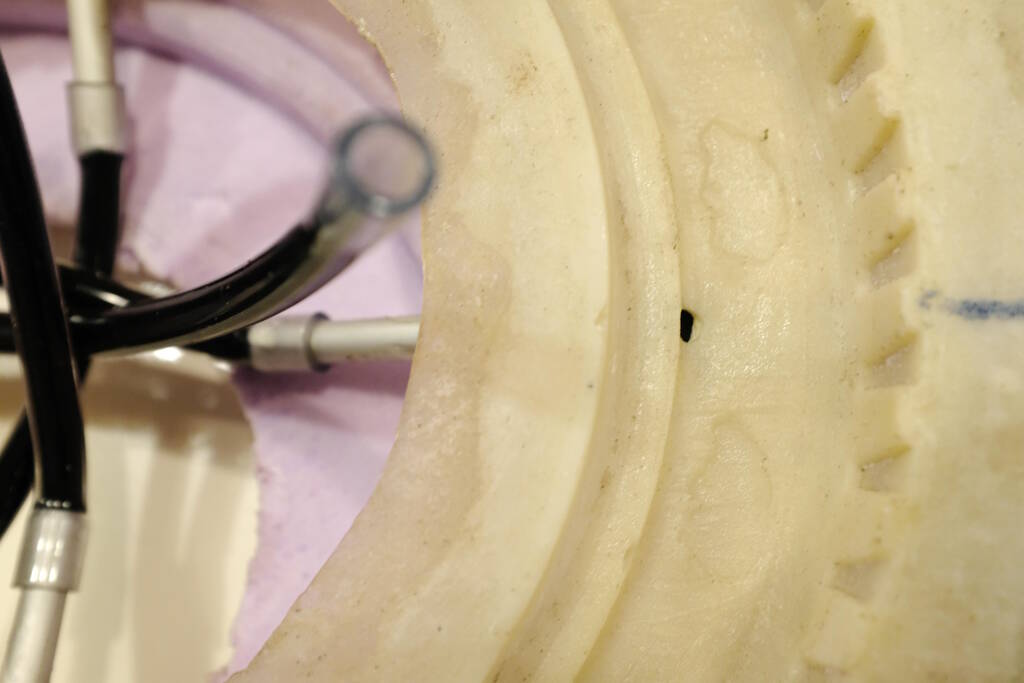
Tubes to vent:
To create something thicker than a foam board, you can consider it as something that is sliced:
Composite Frisbee
Samson and I decided to recreate the Waag Frisbee:
Datasheets
We decided to use Epoxamite and TarBender to compare the results. We also did some test samples with different composite materials. I read the Safety Datasheet of Epoxamite and its Technical Bulletin , while Samson read the those of Tarbender.
After reading the data sheets that gave us plenty of warnings about the severe risks, we compared both materials:
| Value | EpoxAmite | Tarbender |
|---|---|---|
| Mix by volume | 4A:1B | 2A:1B |
| Mix by weight | 100A:24B | 100A:41B |
| Pot Life (minutes) | 11 | 45 |
| Cure Time (hours) | 6-8 | 16 |
| Thin film working time (min) | 30 | 120 |
| Shore D hardness | 84 | 75 |
| Heat deflection temperature (degree Celcius) | 56 | - |
| Exotherm | yes, high | yes, high |
| Release Agent | yes | no |
| Application | laminating | epoxy encapsulant |
| Mixing time (minutes) | 3 (aggressive | 2 (specific instructions) |
The heat deflection temperature is the temperature at which is starts deforming.
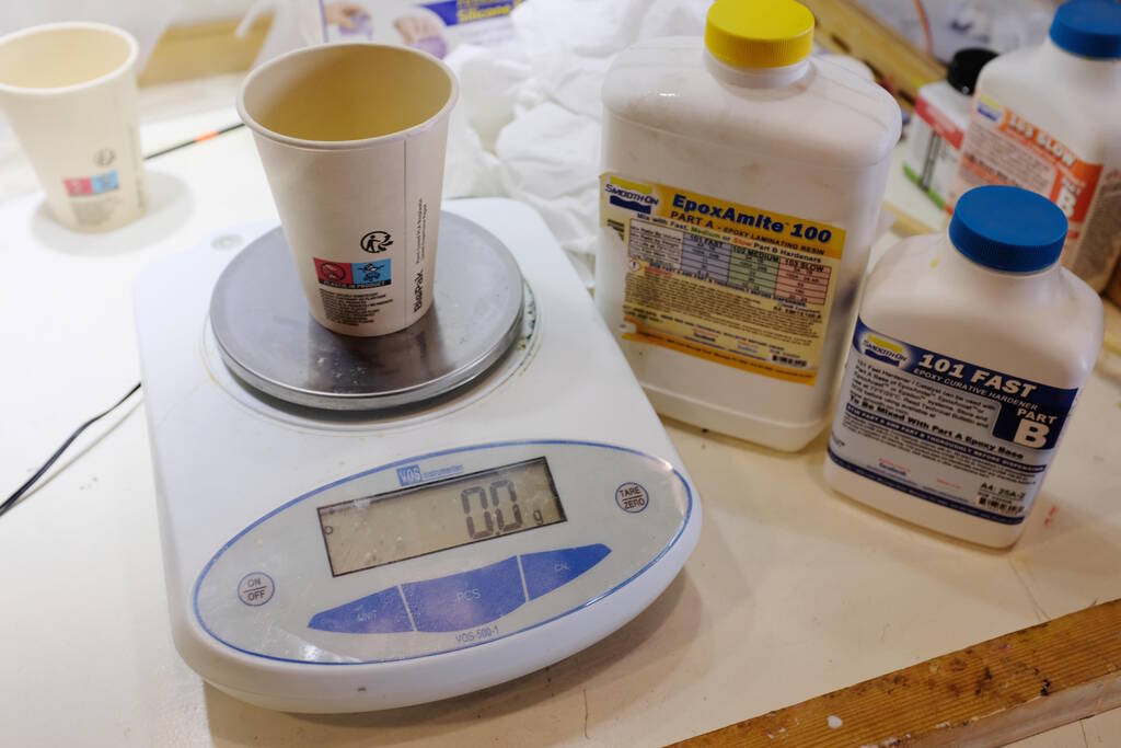
Preparation
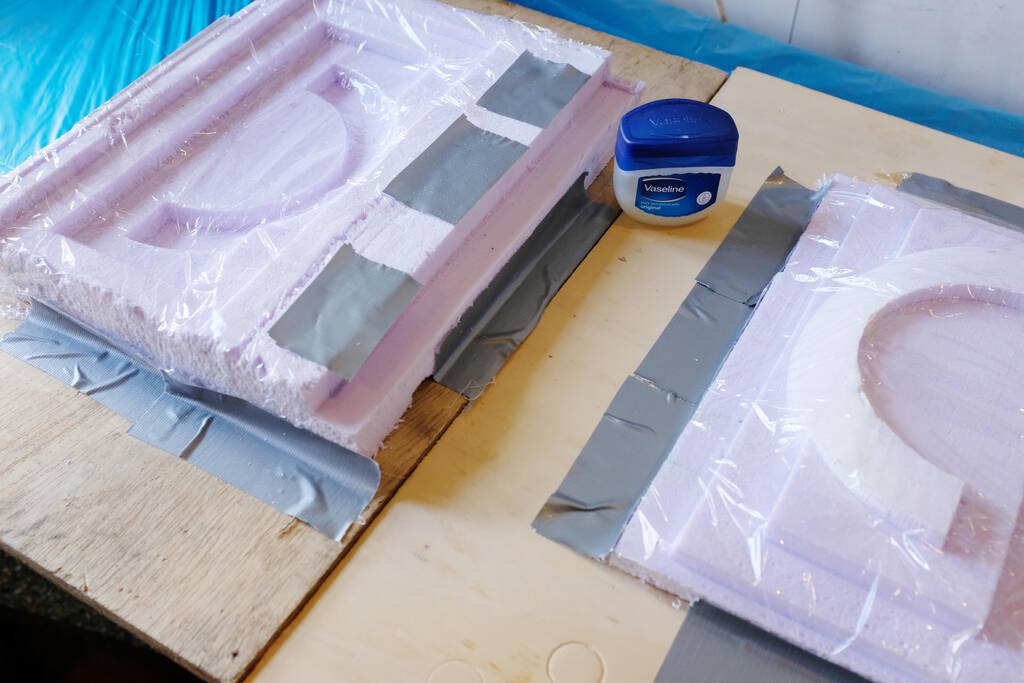
We prepared the molds with vaseline using parchment paper for the top of the frisbee:
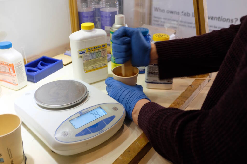
We then measured and mixed the Tarbender (100g A, 41g B)
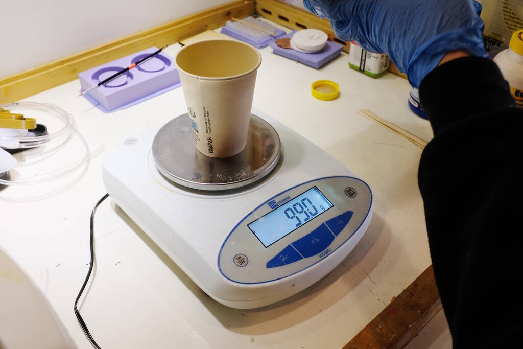
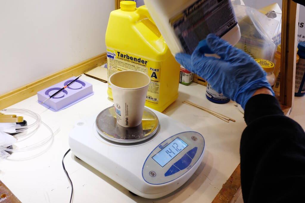
This turned out to be a bit too little because of the test samples, but since the pot life was about half an hour or so, there was plenty of time to mix some more.
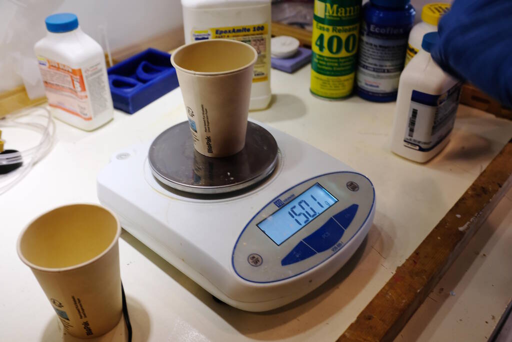
The same process for the Epoxamite (150g A, 36g B). We used a bit more so Samson could do some additional test samples. The pot life for Epoxamite is 11 minutes, so there would be no time to mix more.
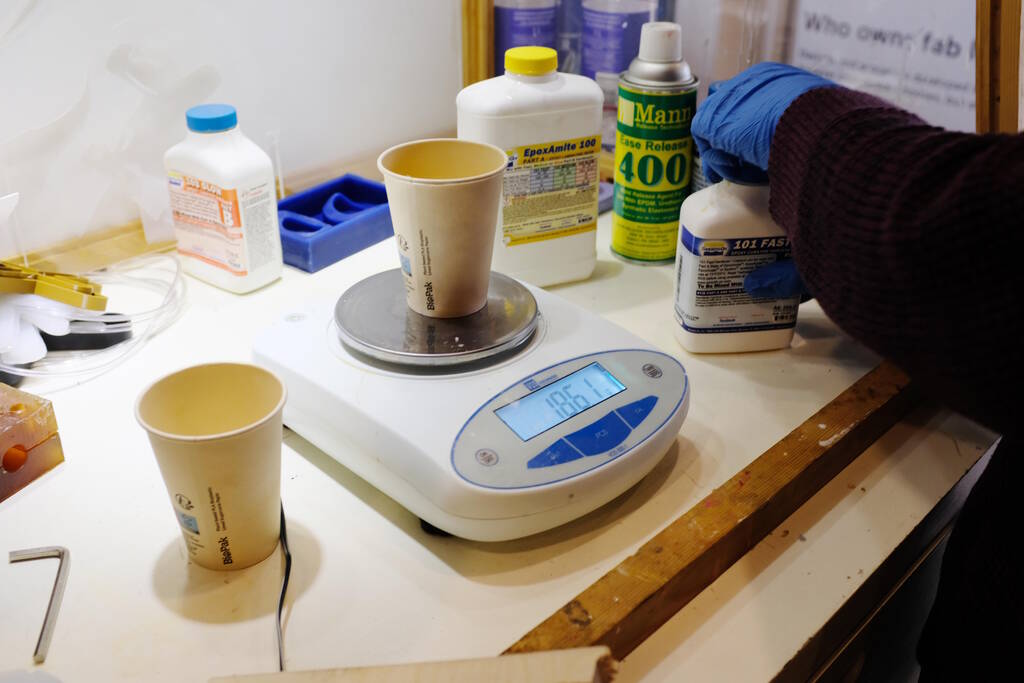
For the Epoxamite, we needed to stir aggresively:
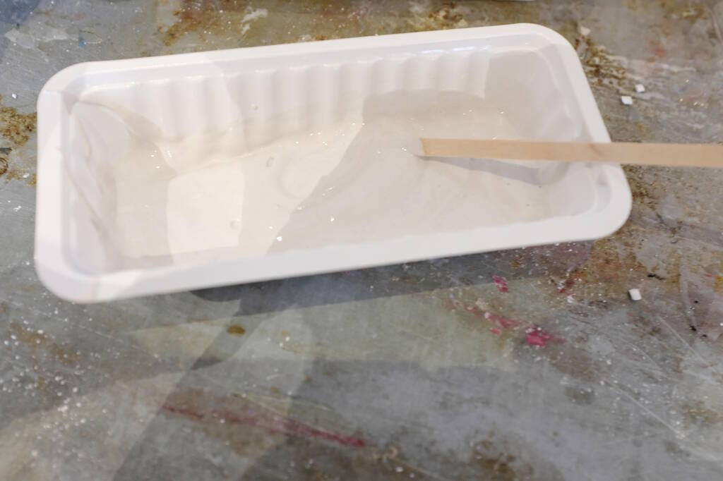
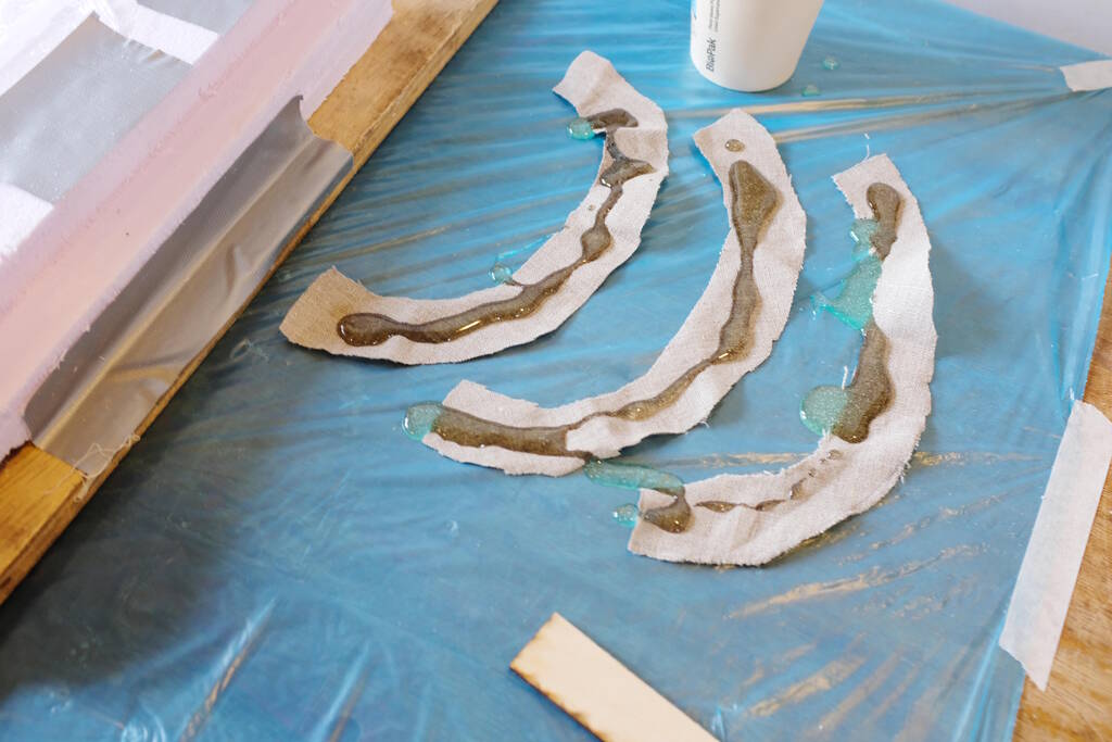
Applying the Epoxy
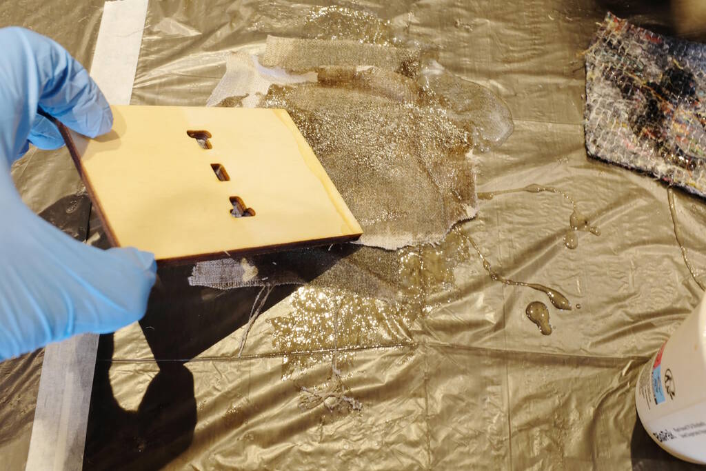
We used these improvized scrapers to soak the materials with the solution:
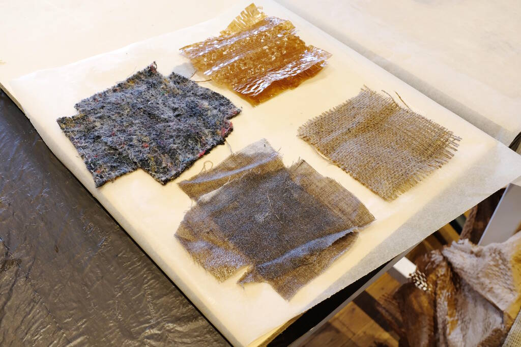
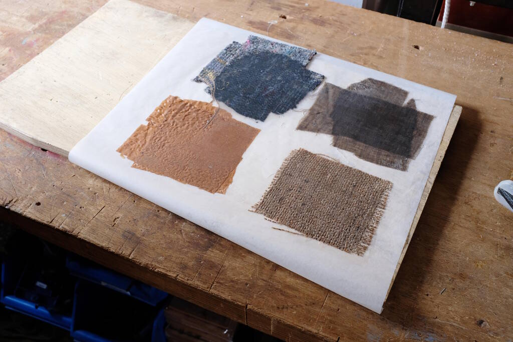
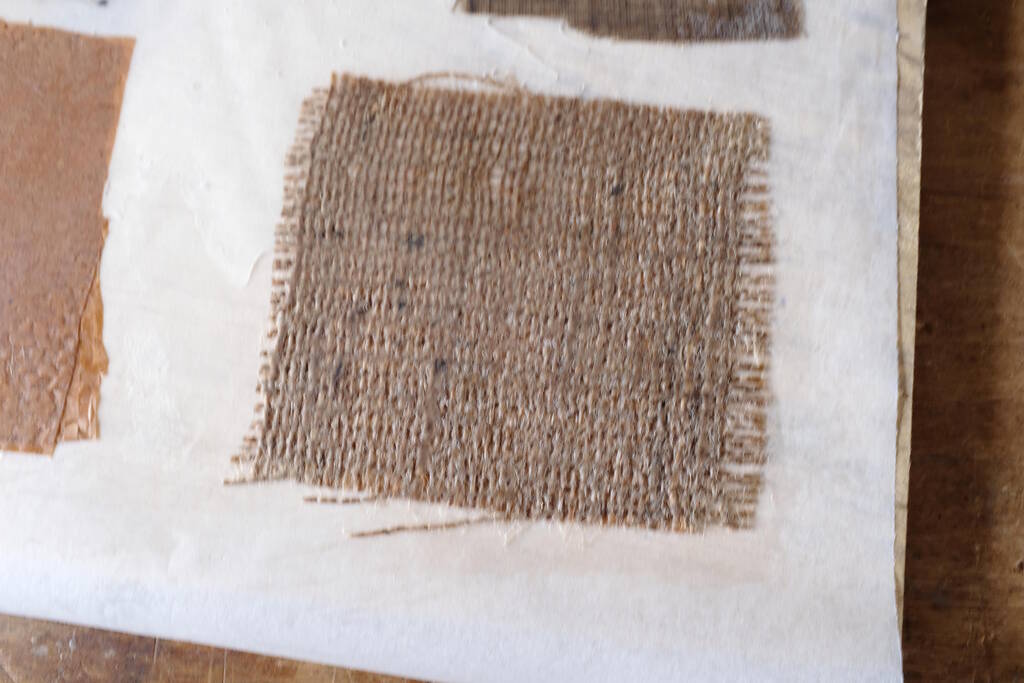
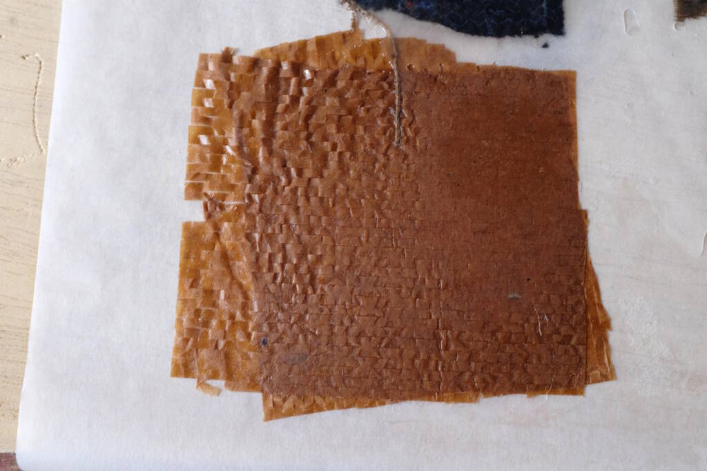
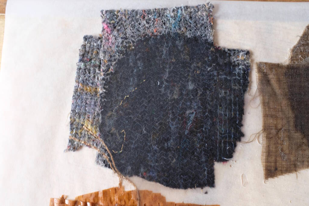
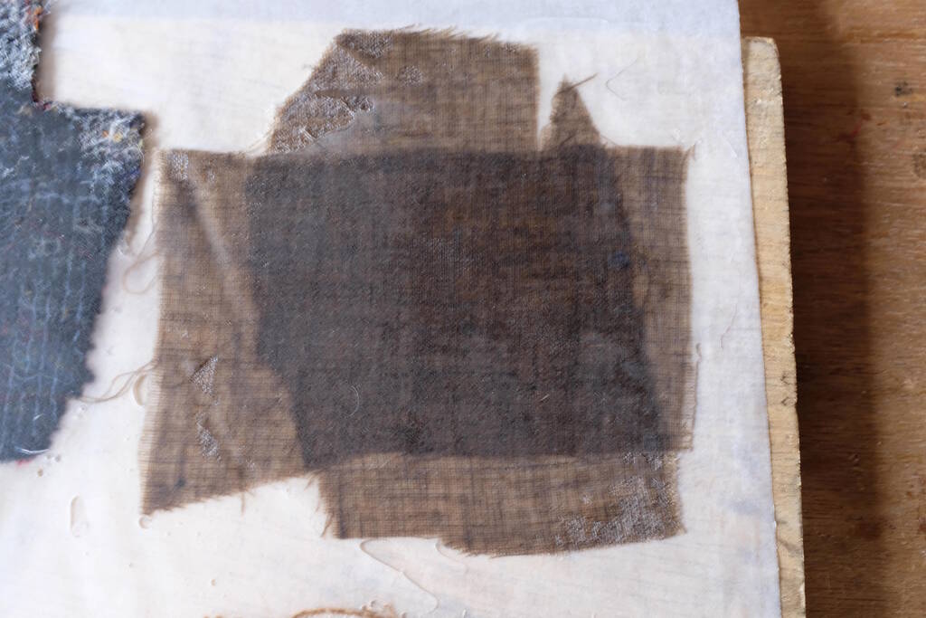
We used the following test materials: thin cardboard-like paper, some thick blueish fabric, linnen, and jute:
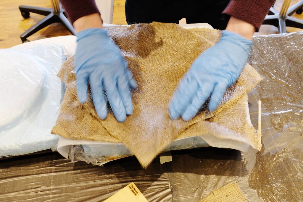
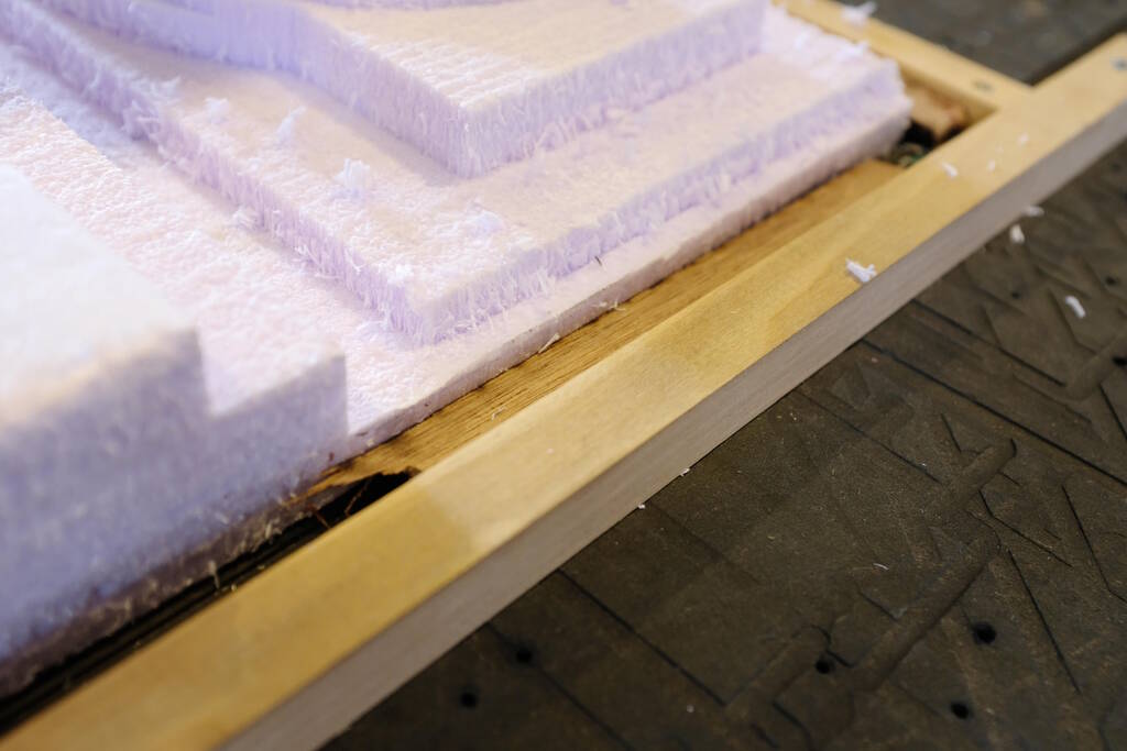
We applied the same for the jute for the frisbee and aligned two sheets crossed:
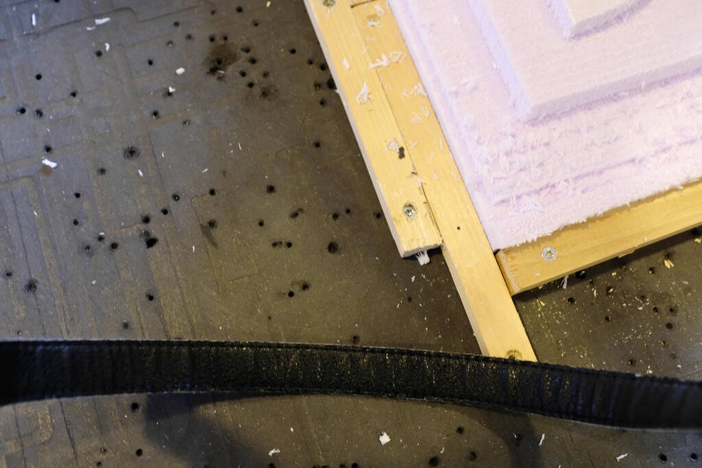
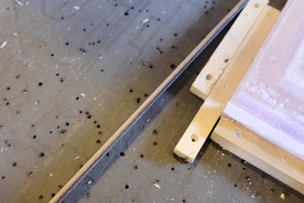
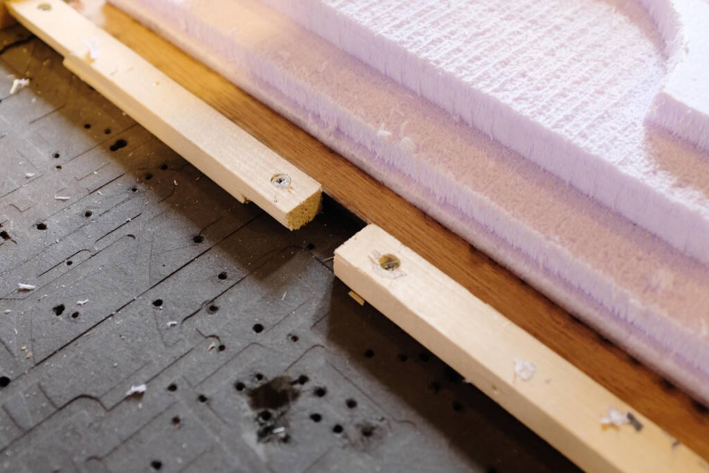
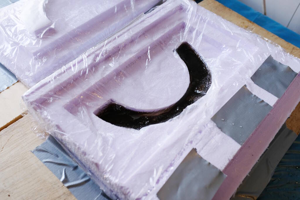
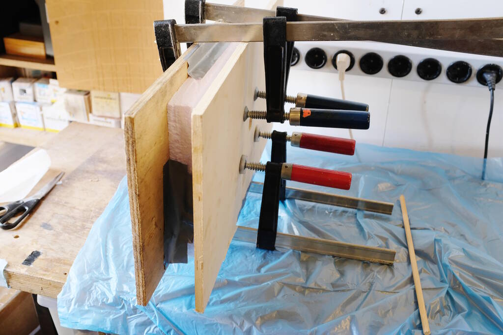
Closing the lid and compress it to let it sit for a day or so:
Unfortunately, we forgot to use parchment paper for the Epoxamite and note that we did the Epoxamite on a different day since we used the same mold.
The Results
The samples came out well:
You can see what each material does:
The following video gives a sense of the strength, flexibility, and how it breaks:
The Tarbender frisbee also came out well:
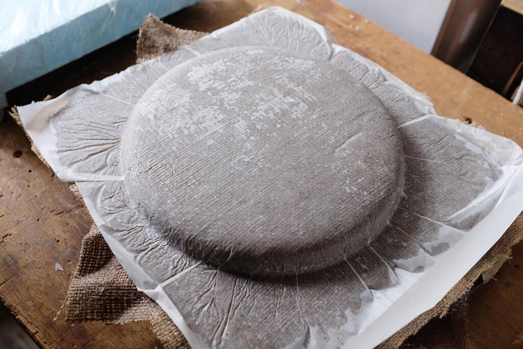
Removing the parchment paper:
The result:
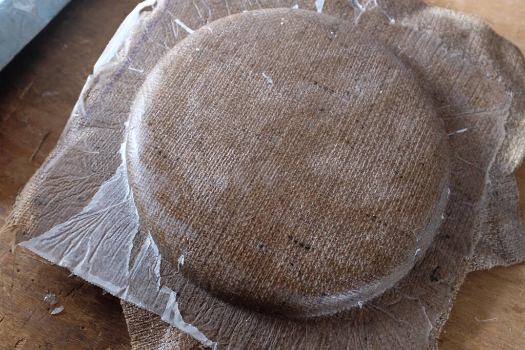
The Epoxamite frisbee was more difficult to extract from the mold:
But it came out well:
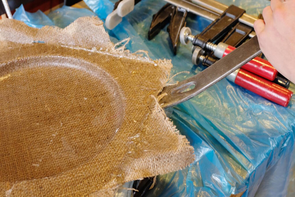
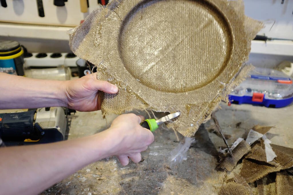
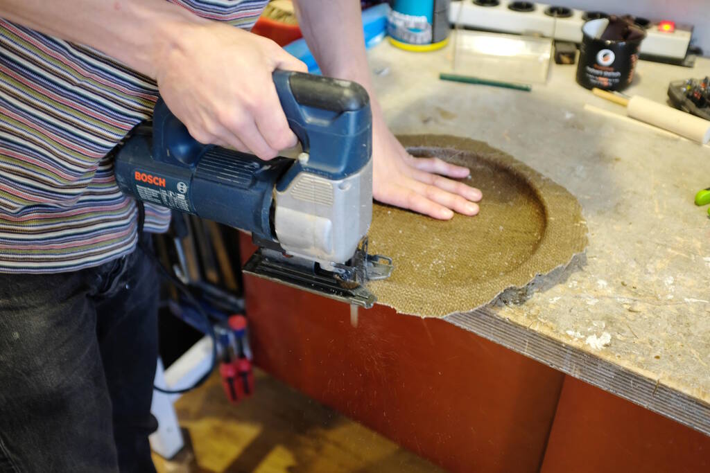
Use the jig saw to make it more Frisbee-like:
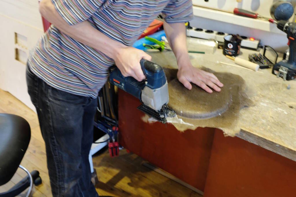
The material is quite sharp and breaks easily:
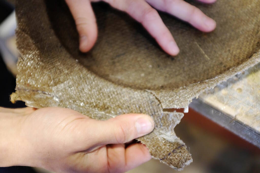
We found that it was better to cut flexible parts first:
and then use the jig saw:
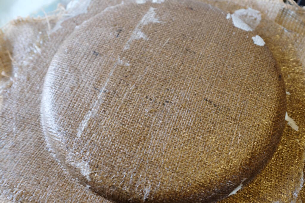
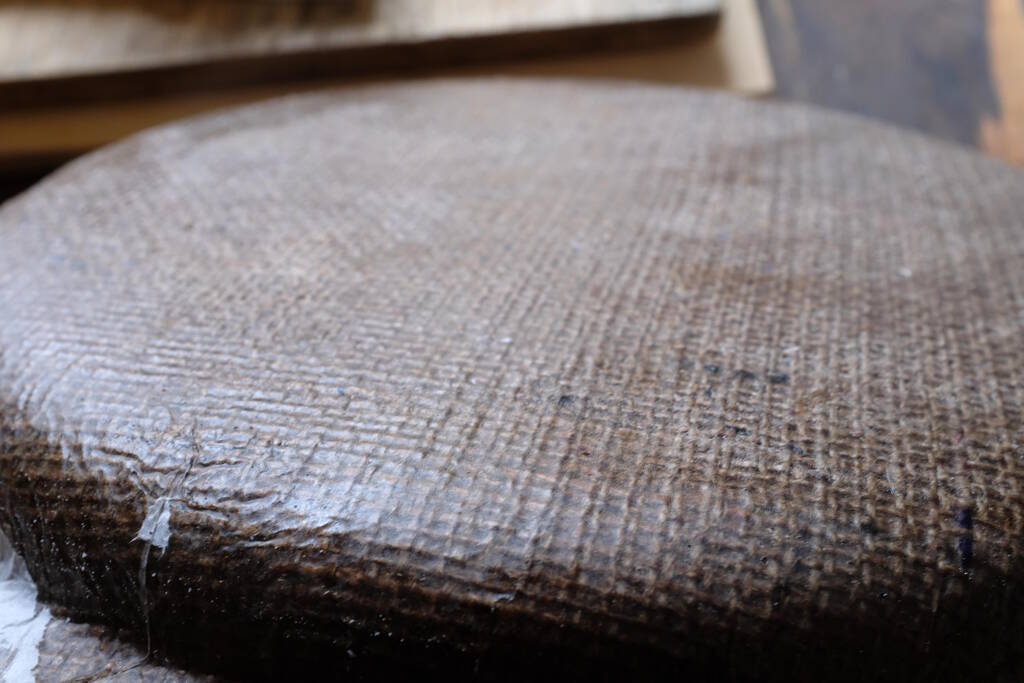
The one with parchment paper (Tarbender) is a bit smoother:
This one is a bit rougher (Epoxamite):
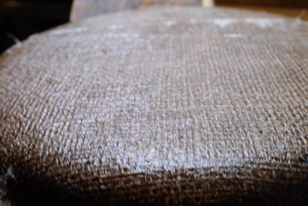
The difference otherwise is hardly noticeable. They appear to have the same strength, flexibility, and hardness.
Designing a Cambered Corner
In this week, I want to apply composite materials to produce a u-turn corner for model race cars, potentially to be used in my final project. Designing the cambered u-turn was more challenging than I thought. I did various experiments with lofts and sweeps (additive pipe in FreeCAD). At first I didn't understand how to make the cambered corner with a sweep because I would have to draw a line in 3D. After I understood that a sweep is indeed the best way to go, I found a way to draw a line in 3 dimensions.
Attempt 1
In my first attempt I applied all the techniques that I used in the final attempt. The result is this:

Unfortunately, the road dips down before going into the corner, so this is not exactly what I'm looking for.

To get this result, I drew the following sketches:

I wanted to use the outside curve for the sweep, so I first drew a line on the XY plane:

Then I drew a line of how the corner should be raised gradually towards the back of the corner. Not that I also drew a shape to extrude (see below).

I then extruded the line on the XY plane upwards:

Extruded the shape based on the gradually increasing line:

And I subtracted this extrusion from the first one:

From that I created a wire that is the line to sweep across:

This results in this cambered u-turn:
The Final Cambered Corner
For the final result, I decided to make sure that the line to sweep over was centered. I also found the curved surface from the side view was not necessary to make a nice u-turn, so I simplified the sketches:

There are three sketches here:
front-left
,
side
(in the
middle) and
front-right
. Not that the track cross-section in the
middle (
side
) is only used to determine the middle point of the
line to sweep across. The final result is different because the sweeping
algorithm may decide to use a different angle. I will show that below.
Based on the middle points of the sections, I drew a line on the XY-plane:

Then the line defining how to raise the corner gradually:

Extruding the XY-plane line:

And the extrusion of the YZ shape:

Subtracting the two:

And making the 3D line to sweep across:

The result is the following by applying the "Additive Pipe" on the
front-right
sketch with the line above. I used the "Frenet"
orientation mode
to acquire the camber in the curve.

As I mentioned before, the surface is not as curved as I defined:

.
I believe this has to do with the constraints of the Frenet algorithm.
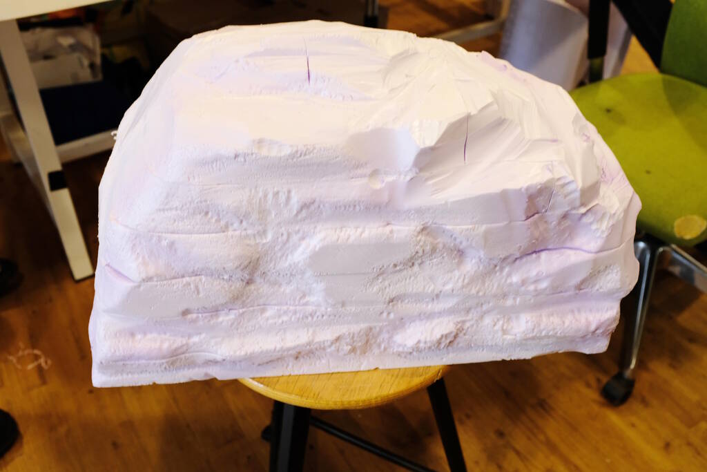
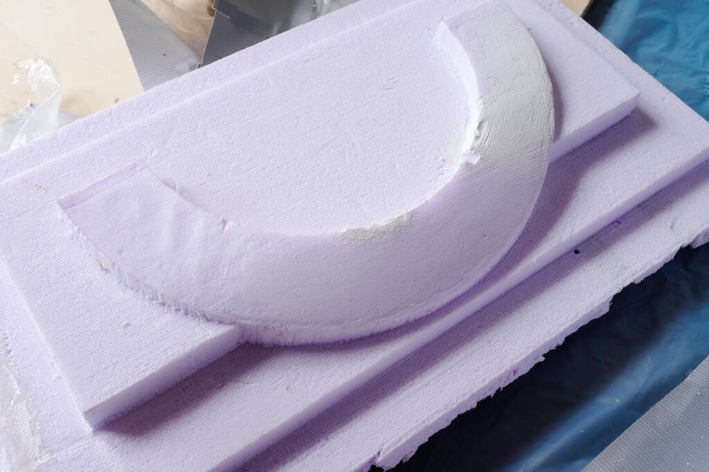
Designing the Mold for the Cambered Corner
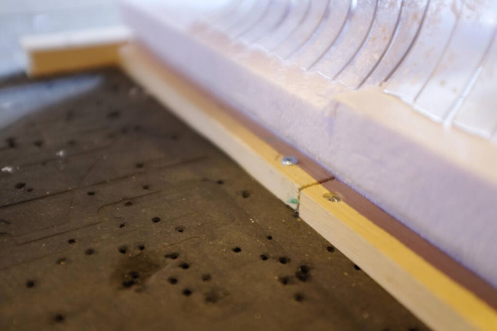
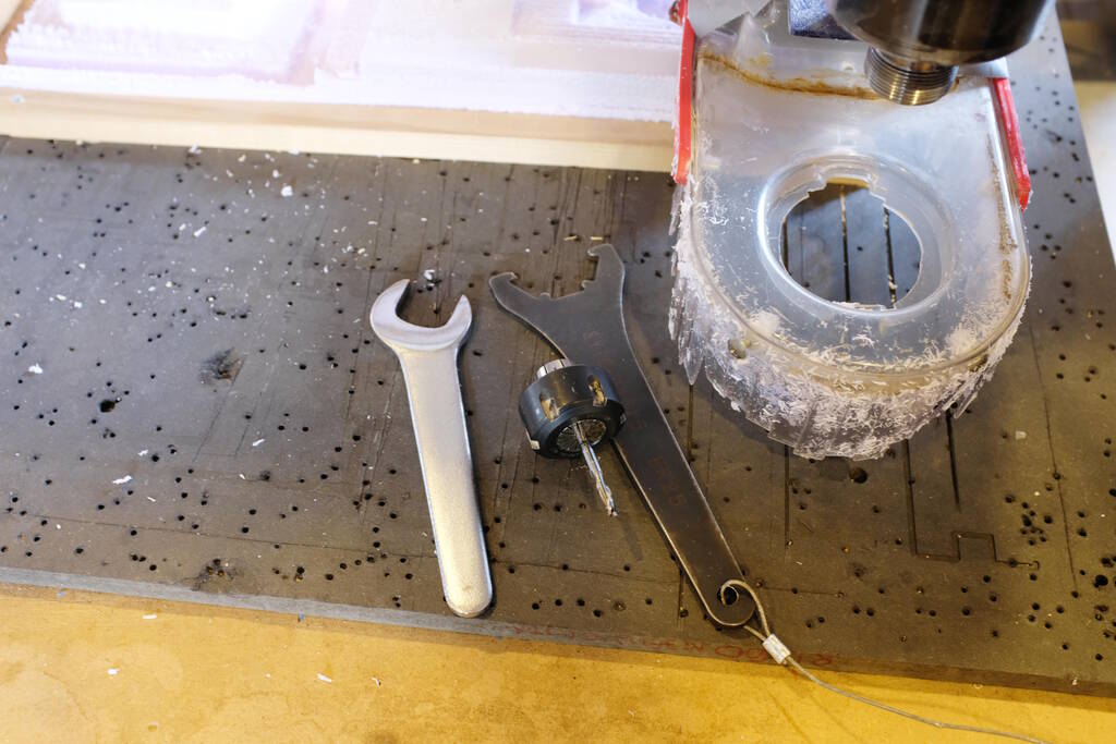
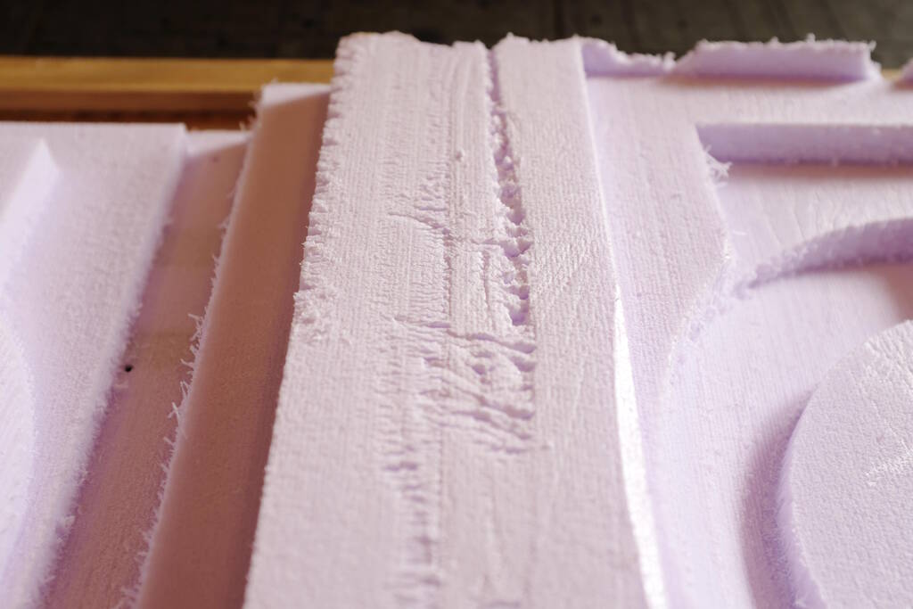
Designing the mold for the cambered corner was more challenging than I anticipated. The height difference of the corner is 23 mm, but the milling bit sticks out only 20 mm. Then there is the collet with a diameter of 42 mm that may hit the side walls of the mold while going deep. I had to change the design of the mold various time to make sure that the collet wouldn't hit a wall.
The measurements of the piece of foam are 470 mm for the length, 330 mm for the width and 50 mm high. In contrast for the casting and molding week, I made sure that this time I recorded the measurements of the stock well and I modelled them already in FreeCAD.
So, given these measurements, I placed the cambered corner inside the foam (a wireframe view here):

I then defined the top of the cambered corner to be a surface that I extrude upwards:

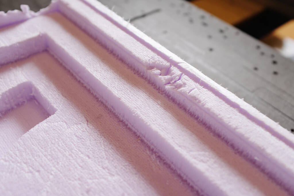
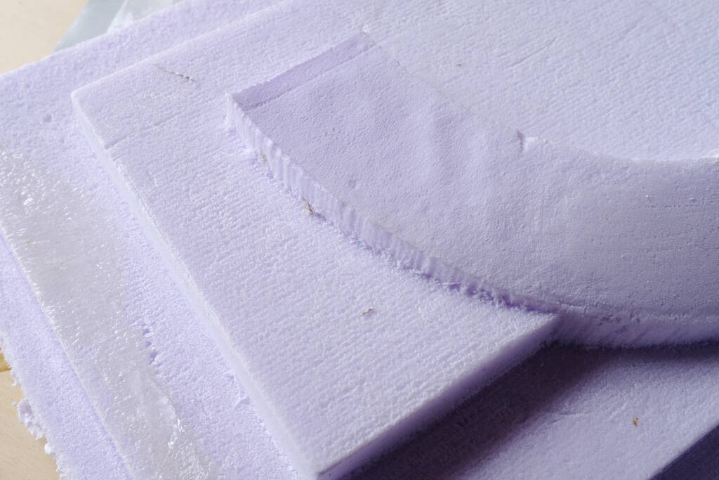
I then cut out a square piece for the lid. Notice that the two ends of the curve are now too deep for the milling bit to reach without having the collet hit something, so I cut out another square piece with margins of 25 mm (the radius of the collet is 21 mm):

The milling bit can now reach all parts without hitting anything.

From this, I extract the lid leaving out the part where the composite material of the corner should reside:

I then cut out a part where the lid should be placed:

And place it such that it exactly fits:

Then there is still a rim that is too high with which the collet will collide, so we cut out another 25 mm piece:

Setting up VCarve
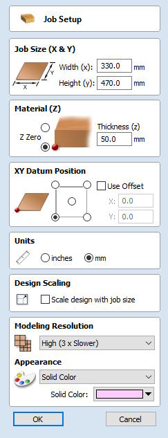
Job Setup
First, I set up the job settings in the same way as I modelled the foam in FreeCAD:
The inner workings of VCarve maintains to ellude me. To me the following settings seem to be correct. The foam is inside the red boundaries that (I believe) define the material setup.
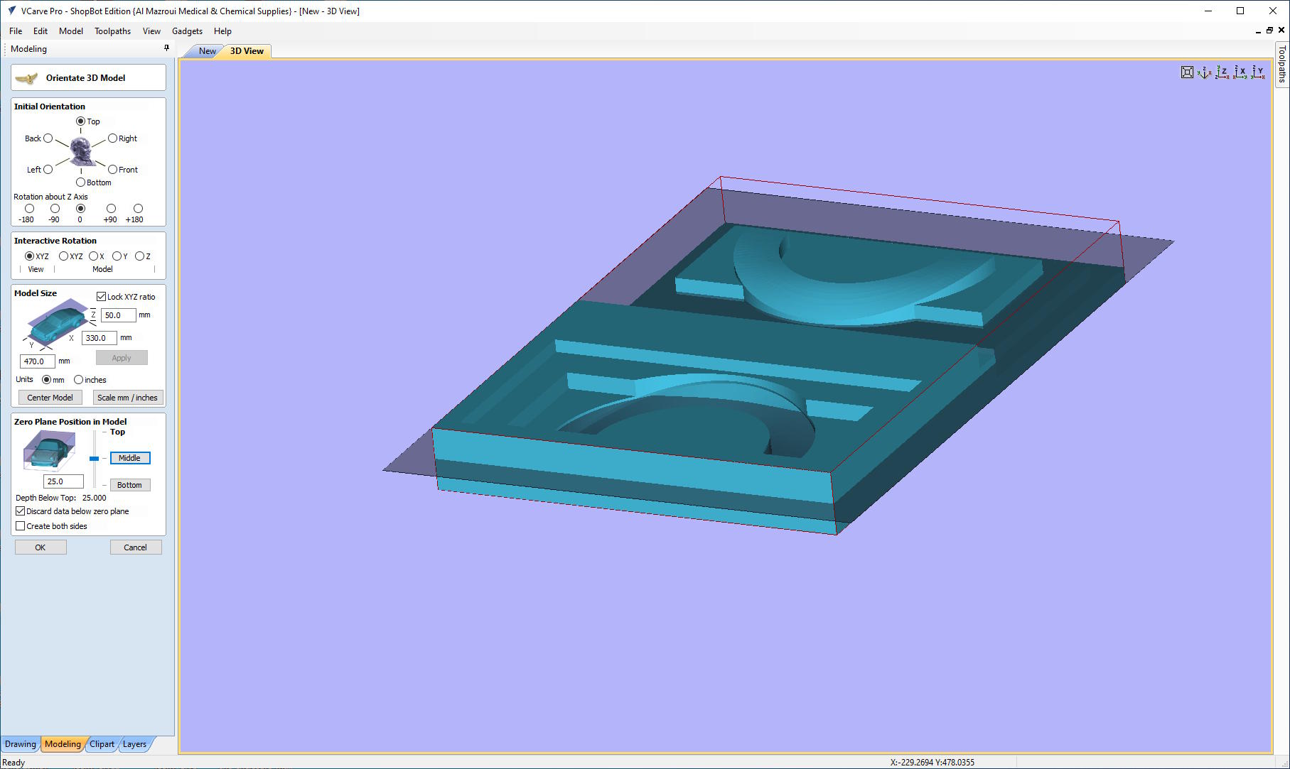
However, this is incorrect. Apparently, I need to set it like this, on top of the plane that cuts through the boundaries of the material:
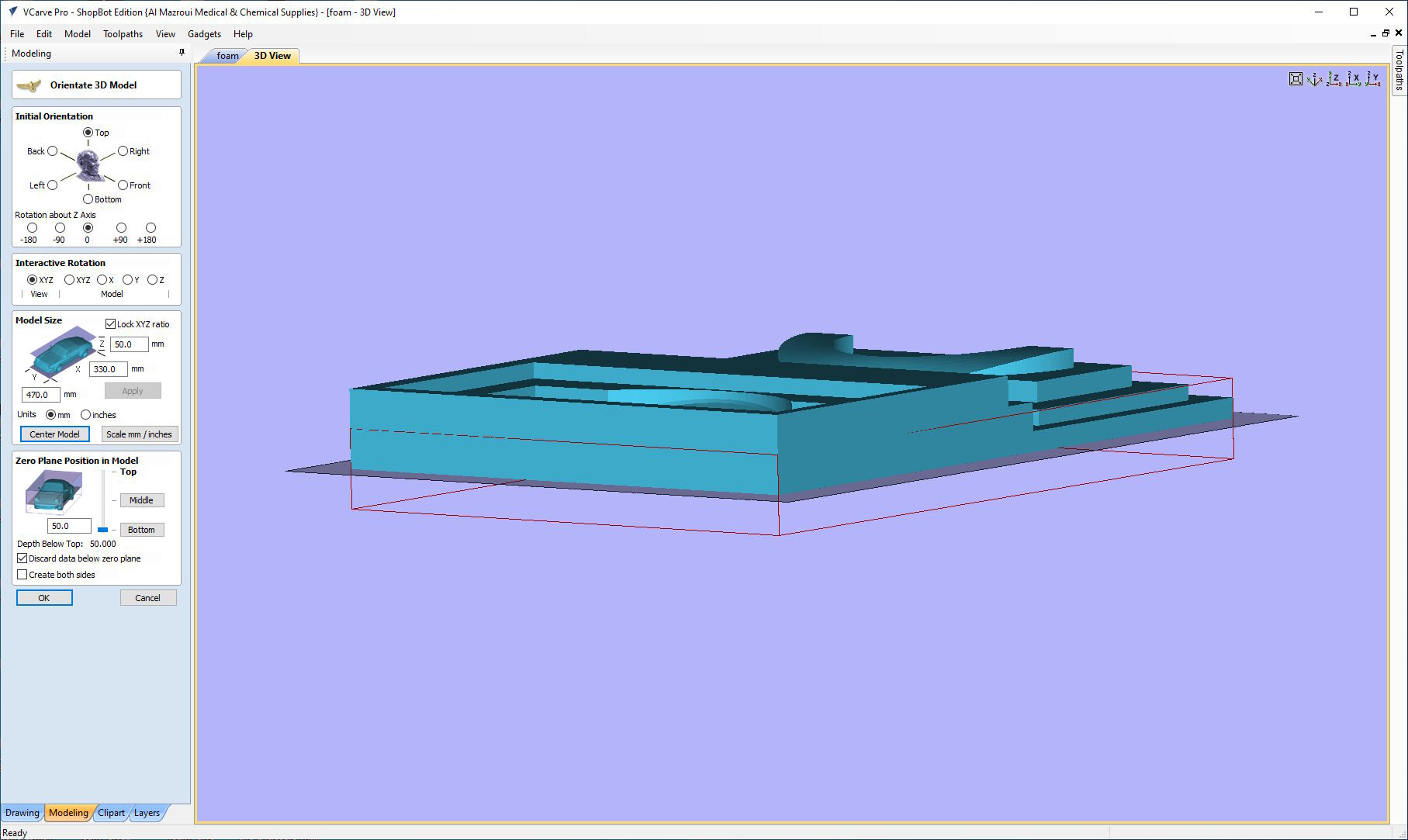
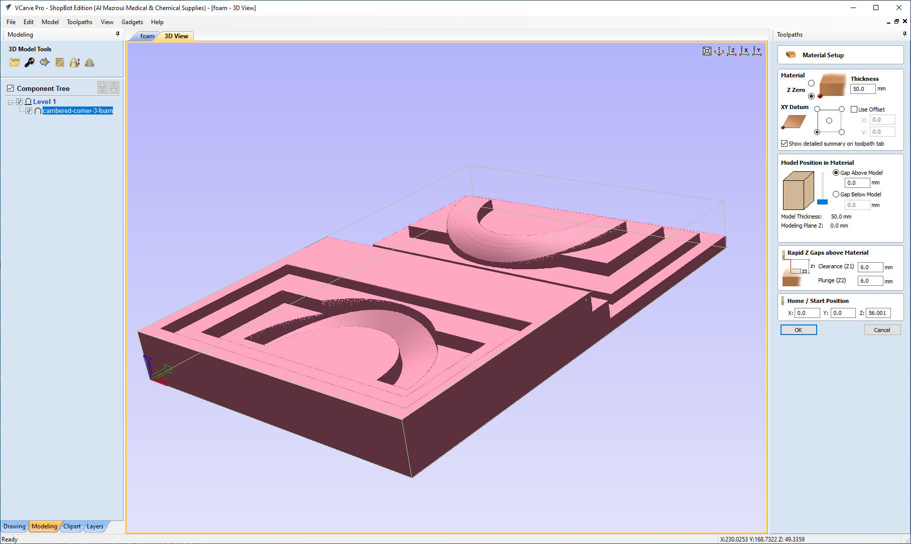
Then when setting up the material it looks right to me:
Defining the Toolpaths
For the rough cut, I used the following tool settings:
| Setting | Value |
|---|---|
| Type | End-mill |
| Diameter | 5 mm |
| Pass Depth | 5 mm |
| Stepover | 4 mm (80%) |
| Spindle Speed | 8000 RPM |
| Feed Rate | 120 mm/s |
| Plunge Rate | 25 mm/s |
For the finishing toolpath, I used a smaller diameter because I have quite some sharp corners in the model. The settings:
| Setting | Value |
|---|---|
| Type | End-mill |
| Diameter | 3 mm |
| Stepover | 0.6 mm (20%) |
| Spindle Speed | 8000 RPM |
| Feed Rate | 100 mm/s |
| Plunge Rate | 25 mm/s |
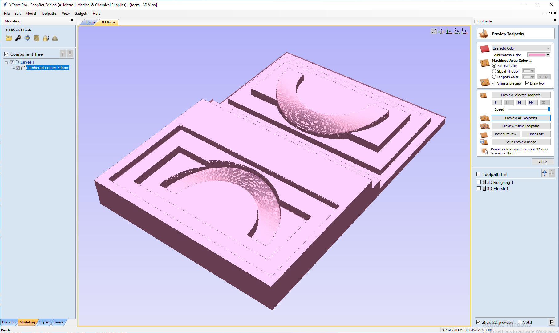
The Simulation
The simulation of the toolpaths looked good to me:
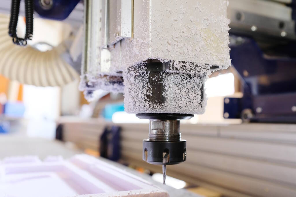
Milling
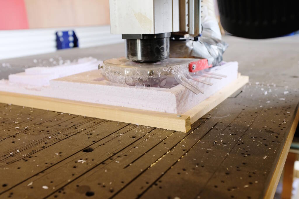
The Rough Cut
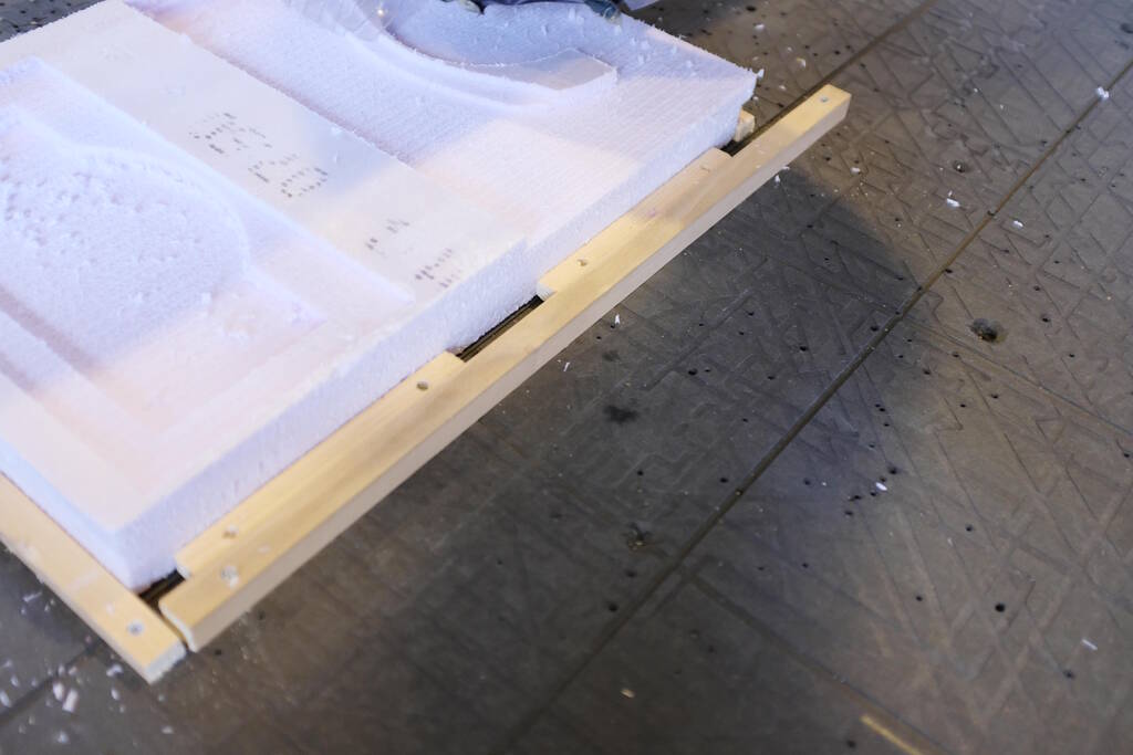
I wanted to use double-sided tape to fixate the foam to the bed of the CNC, but the tape was missing. Henk suggested to use wooden beams which I did:
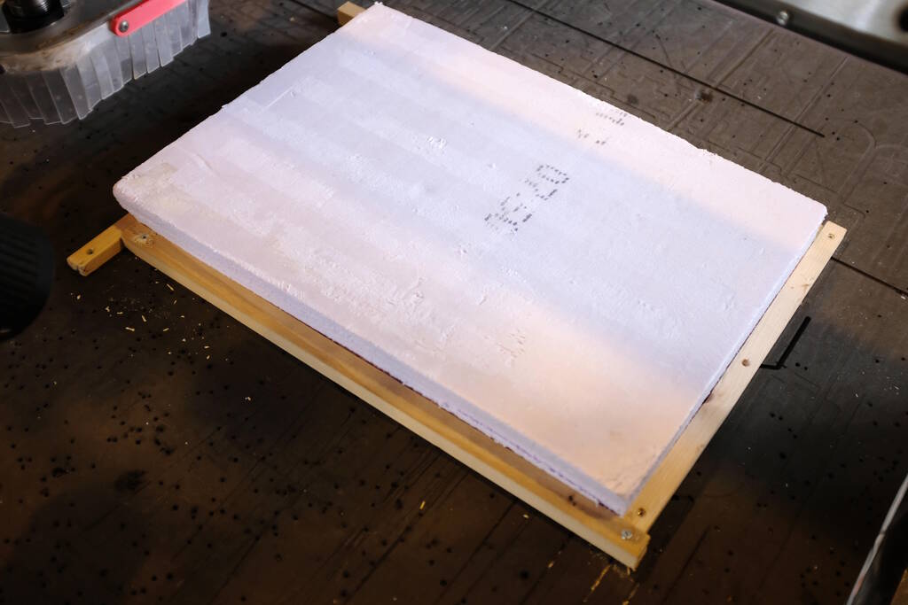
I Z-zeroed the machine and notice the wooden beam underneath the foam. I measured the length of the foam at the top but the foam had been cut about a cm in. This will lead to problems up ahead...
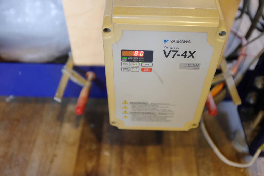
I used a speed of 8000 RPM:
The milling appeared to go well:
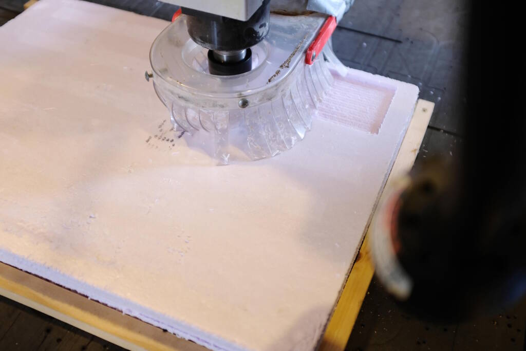
Then I noticed that the milling bit would extend beyond the wooden beam which had screws:
So I checked in my model if there was risk whether the milling bit would hit the beam and/or the screw. Well, the milling bit would not go deeper than 13 mm and the wooden sticks above were 12 mm, so I have space of 1 mm, but not very comfortable. However, the stick on the long side was much higher, so I solved it with clamping the 12 mm sticks without screws with the just removed stick:
In the end, it turned out that the 1 mm was indeed enough at least for the rough cut:
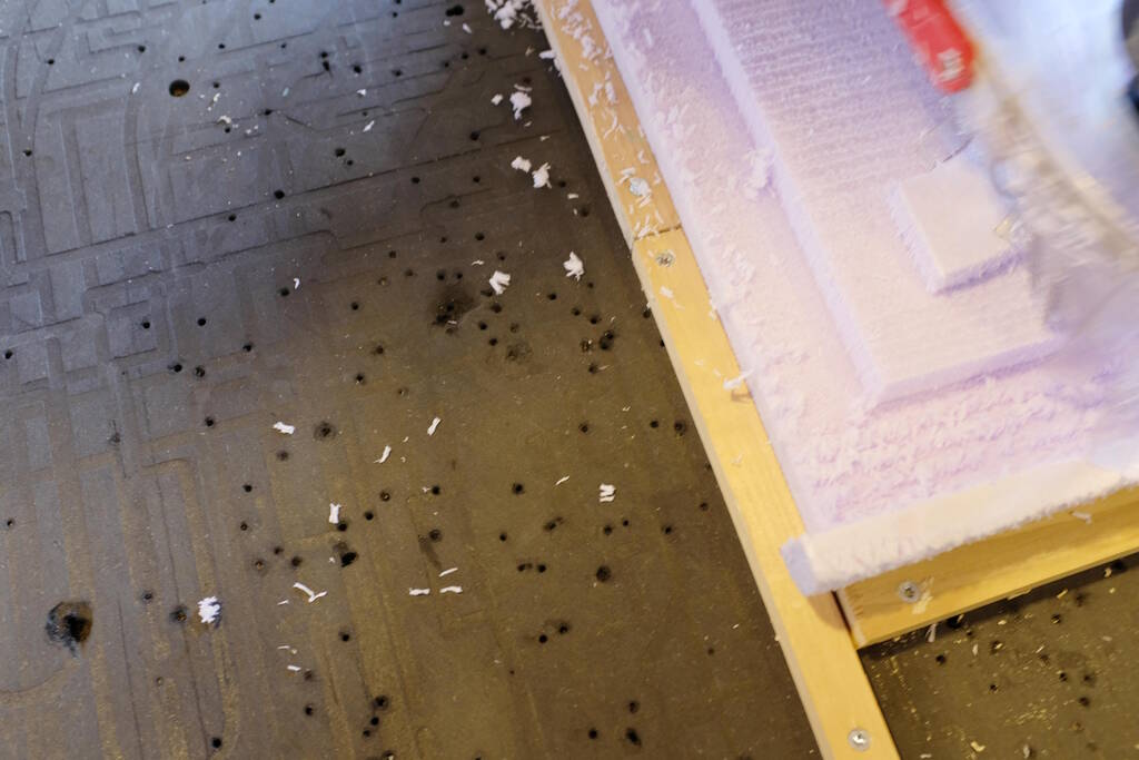
For the finishing path I wanted to have a better solution. I paused the machine to get rid of a rim that extends a bit outside of the modeled foam (the foam was not completely straight):
For the finishing cut, I solved the screw/height problem with this solution:
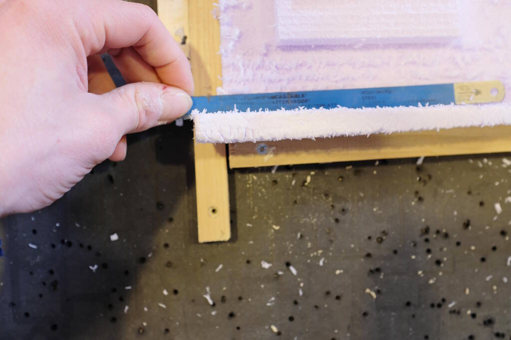
However, I then found these thin beams of which I would be sure that it could hold down the foam and be low enough not to hit anything:
I also used it for the long side:
The Finishing Cut
For the finishing cut, I changed from the 5 mm end mill to the 3 mm end mill:
I had to zero again, of course, and start the new job.
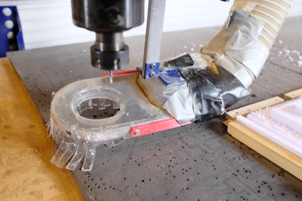
While milling, the skirt was very close to the rest of the model:
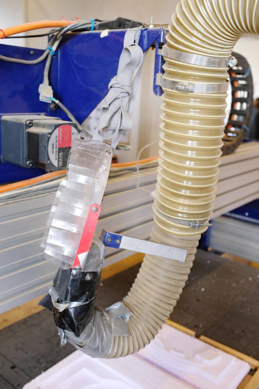
It is destroying a side wall, but that has hardly any function. Later however, it was destroying something that was critical for the design:
This piece should be nice and smooth for a good finish at the top surface of the corner, but the skirt was hitting it. I asked Henk and he recommended to abort the job, take good care of the position of the file and remove the skirt. Getting it off the machine here:
Attaching it safely to the machine such that it moves with the head and cannot come close to the milling bit:
Restarting the Job
I recorded the exact position of milling head and on which line the machine was:
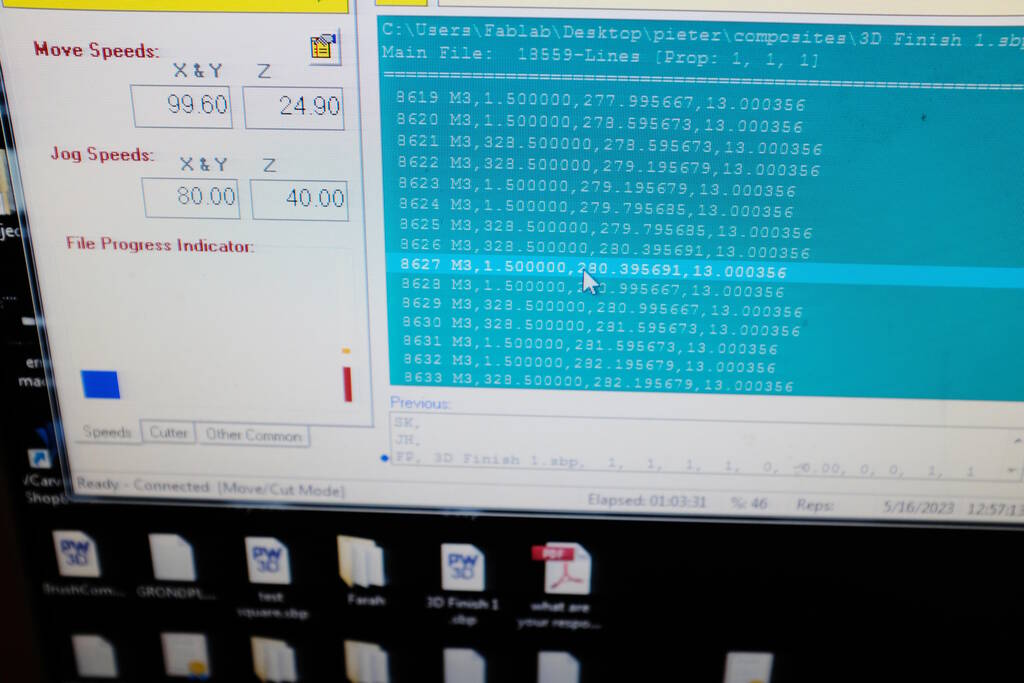
This means that the machine is about to execute line 8627. I edited the file and left the relevant header in:
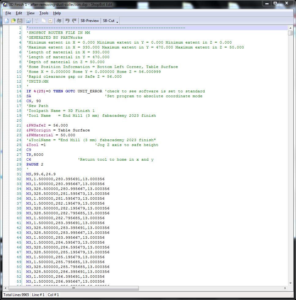
This means that the machine executes the instructions in the header, sets the move speed (MS) to 100 mm/s and 25 mm/s (plunge) and then line 32 is what used to be line 8627. This worked out perfectly well and the job was resumed.
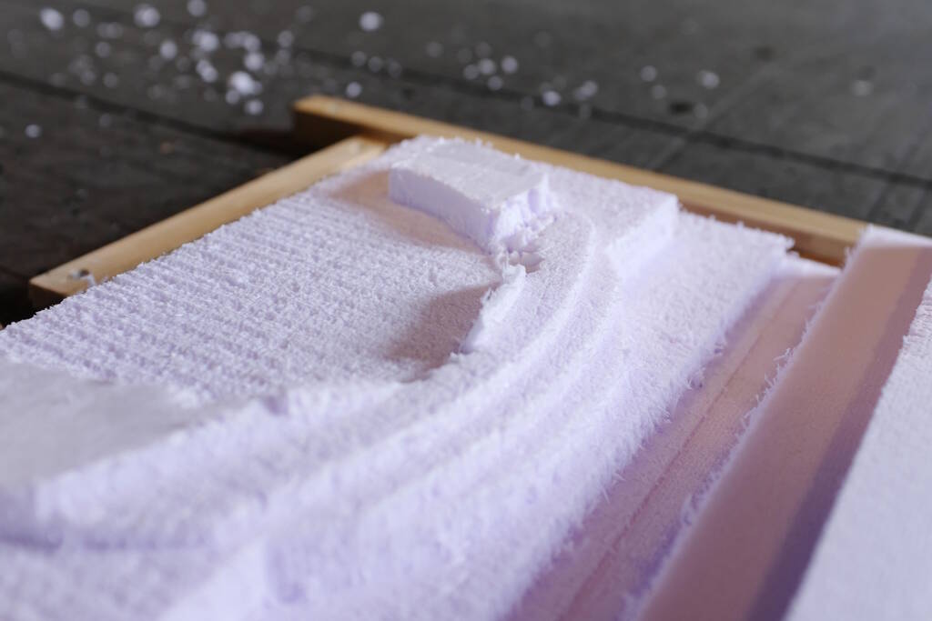
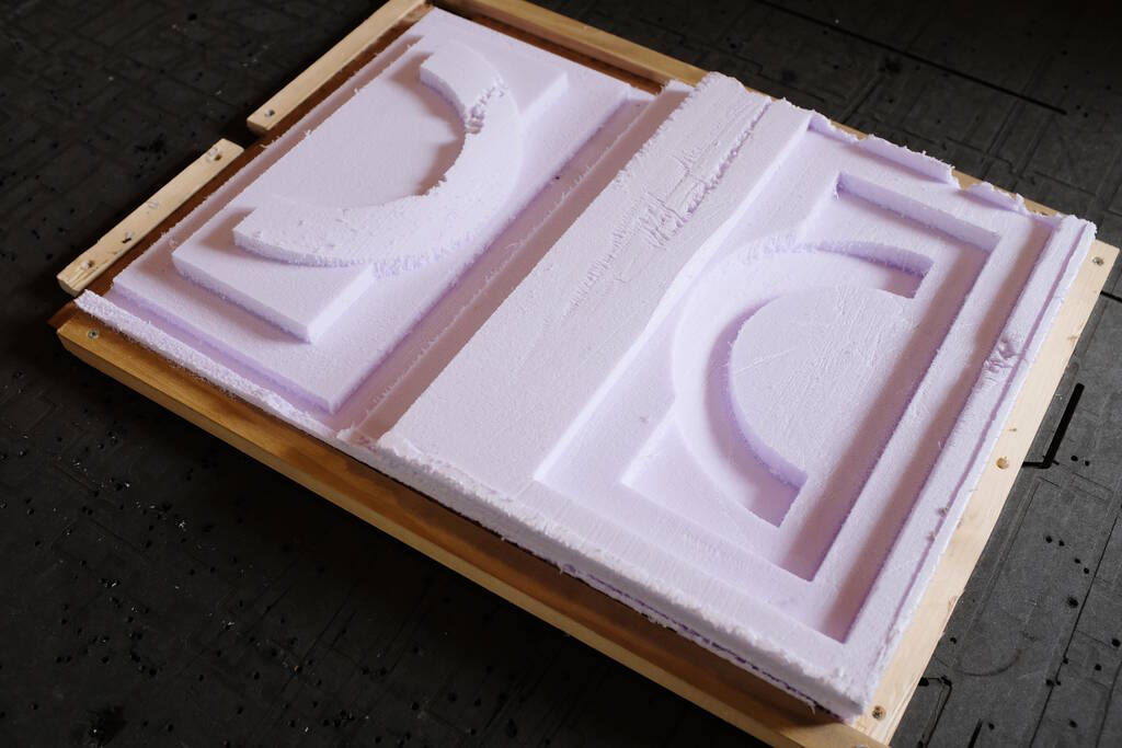
The Result
The amount of foam slivers was all right:
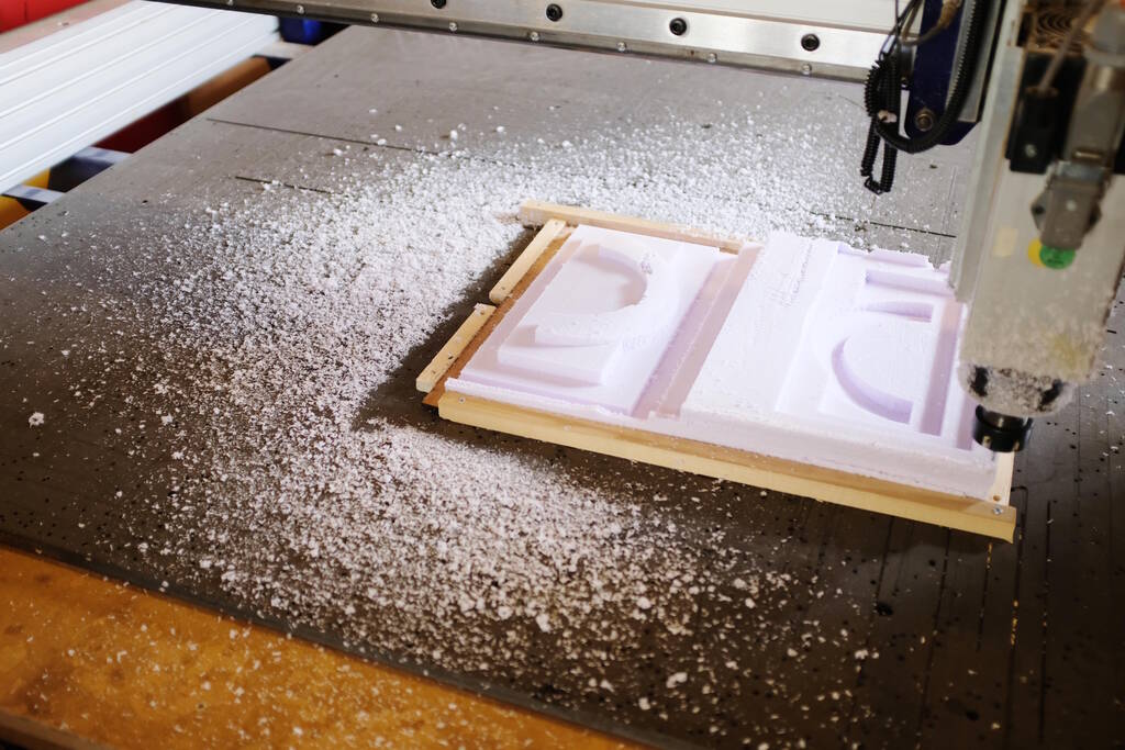
The head was a bit dirty:
It is easy to clean with a vacuum cleaner since the material is so light.
This is the end result:
With this part destroyed...
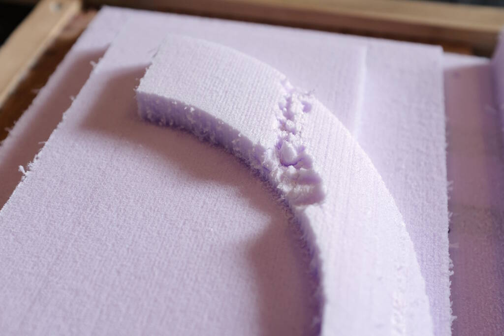
Apparently, the collet had hit a side wall after all:
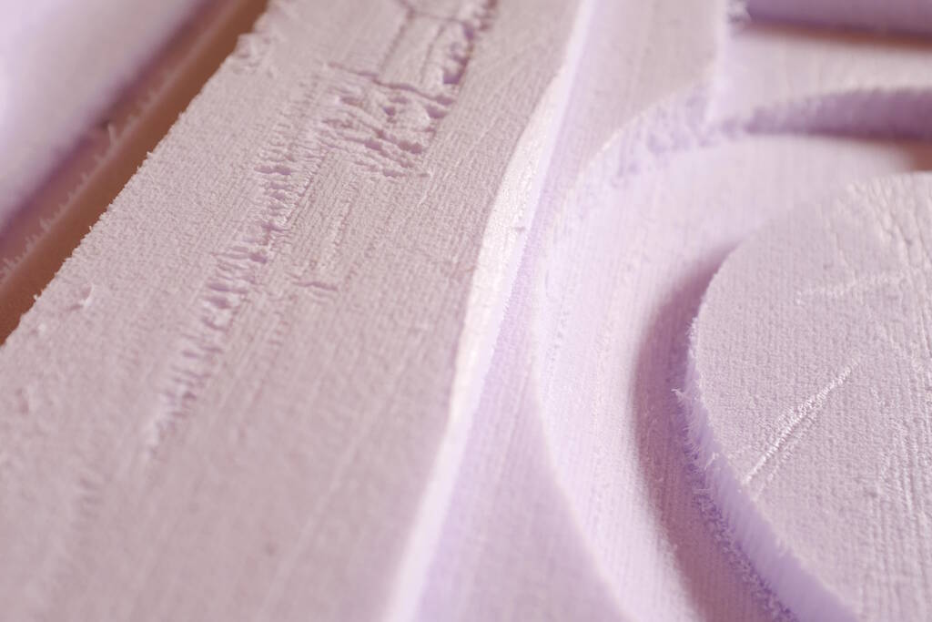
The skirt also messed with the surfaces below, but those are not critical:
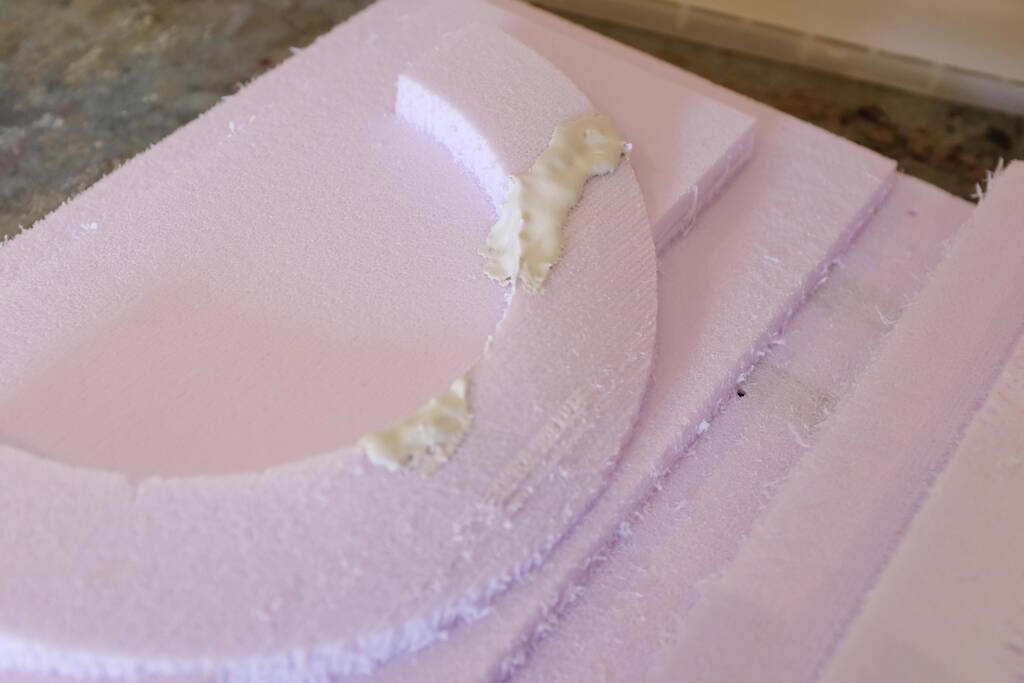
Fix the Mold with Gypsum
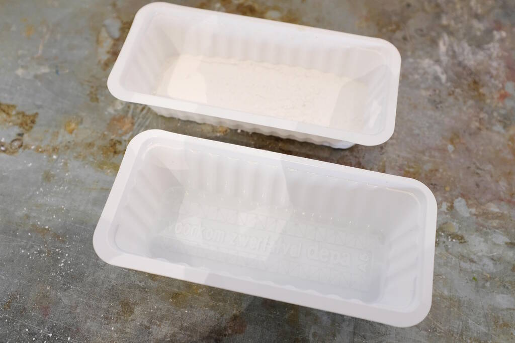
I never really worked with gypsum before, but it turns out to be great to fix these kinds of problems. I mixed two parts gypsum powder with one part water:
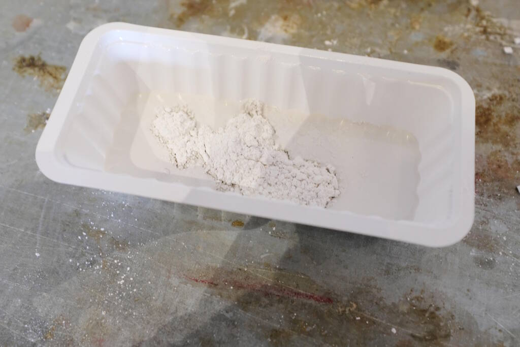
I had to let it sit for a couple of minutes and then stir:
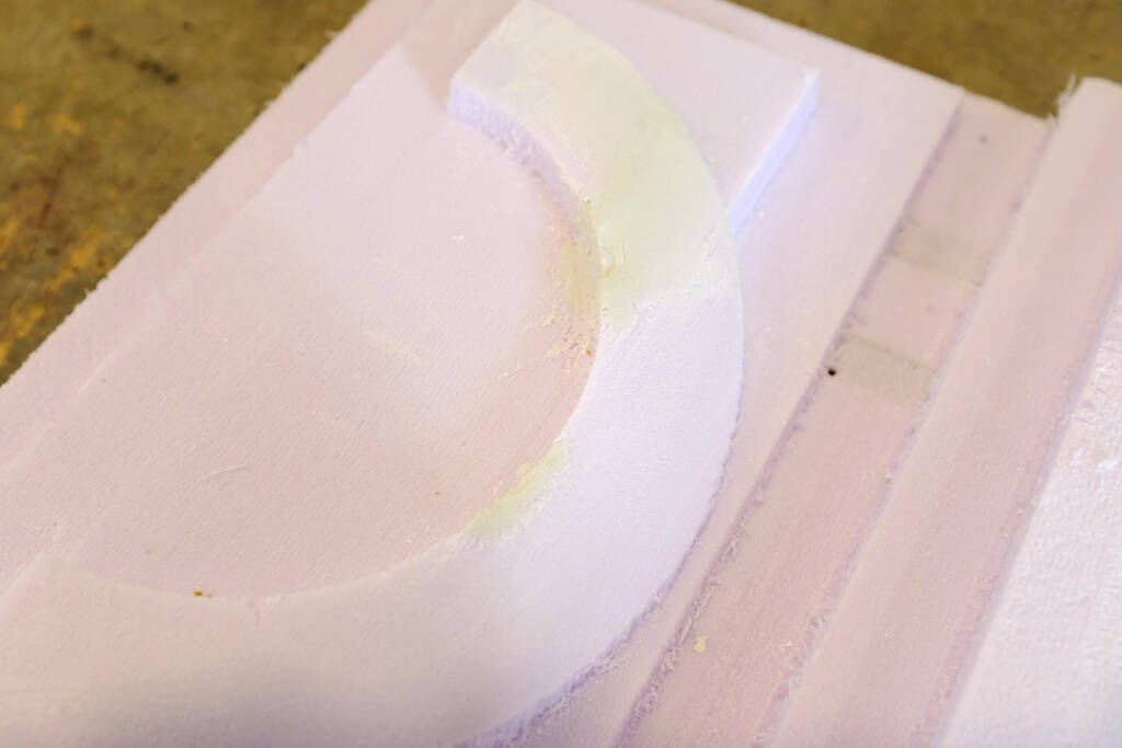
I then applied it to the model:
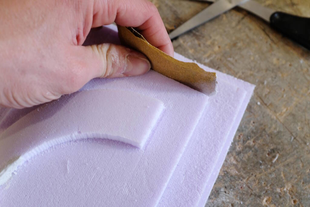
And sanded it down after 45 minutes or so:
Casting
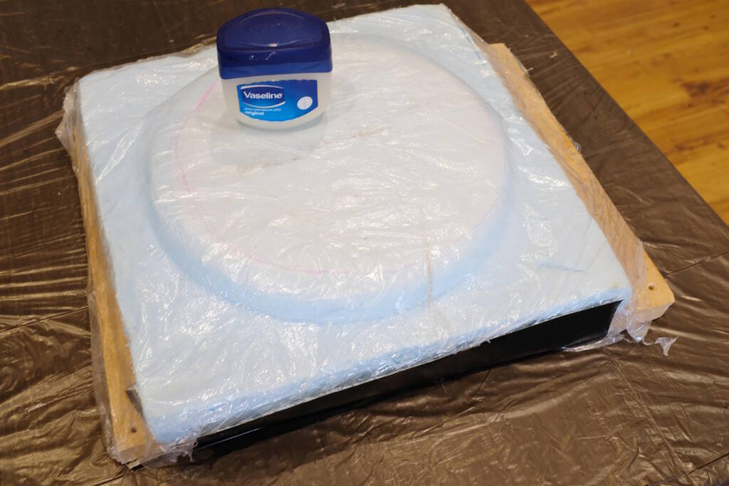
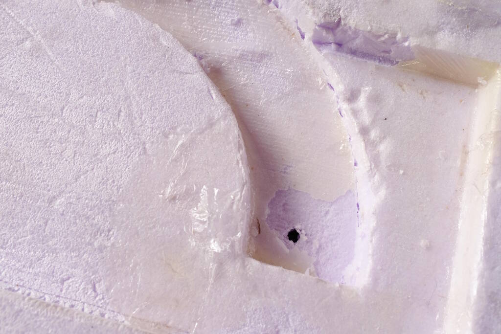
I realize now that I didn't leave any margin for the lid, so I had to sand it a bit to make it fit properly. It is very tight though...
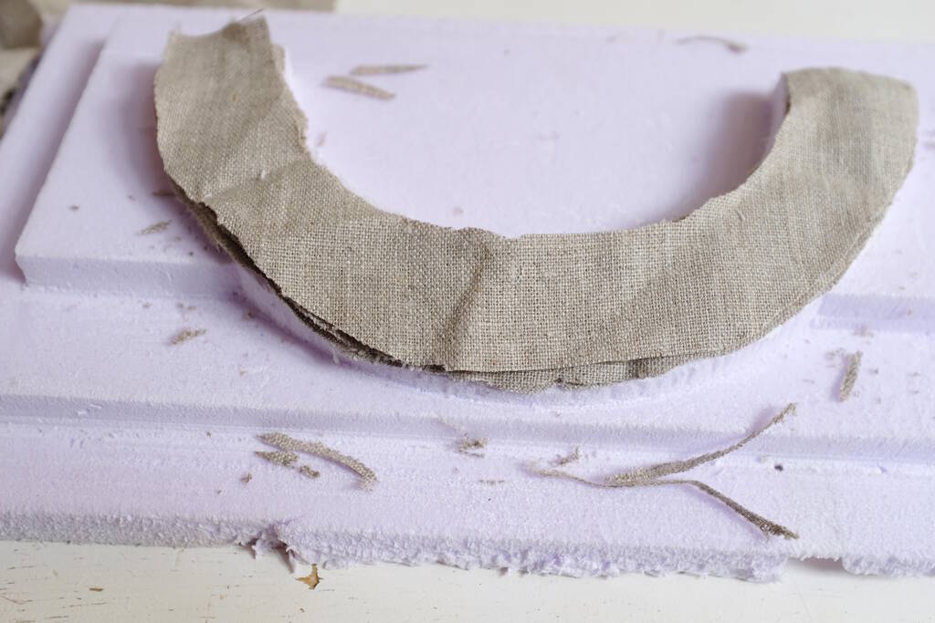
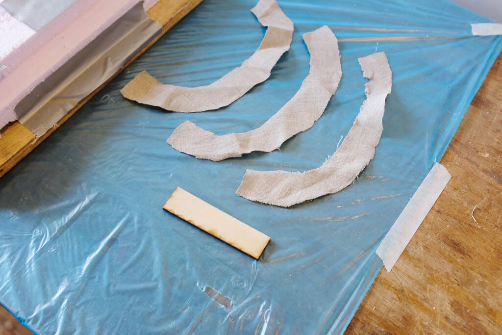
I cut three pieces of linnen to use as composite material
I added foil to the mold:
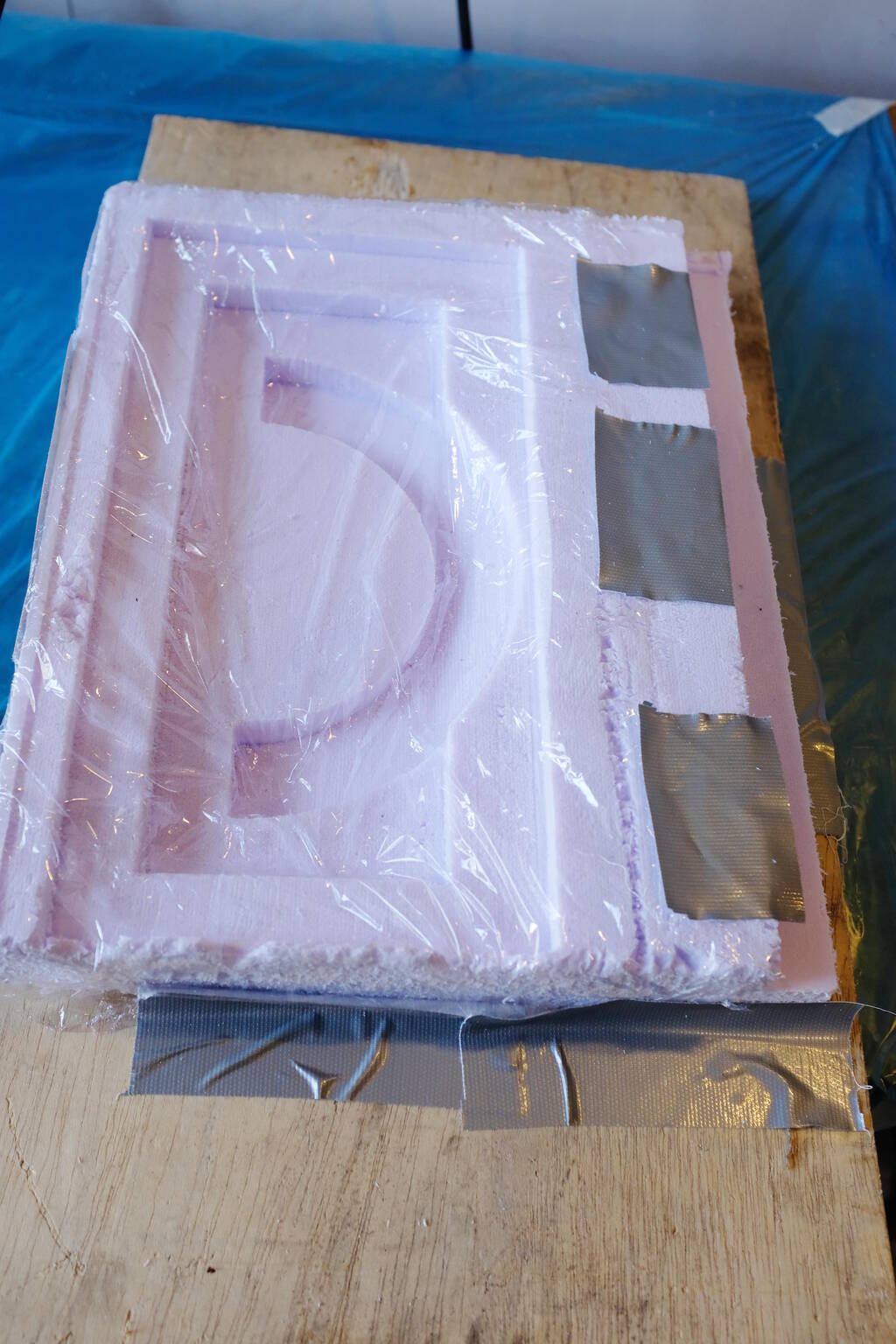
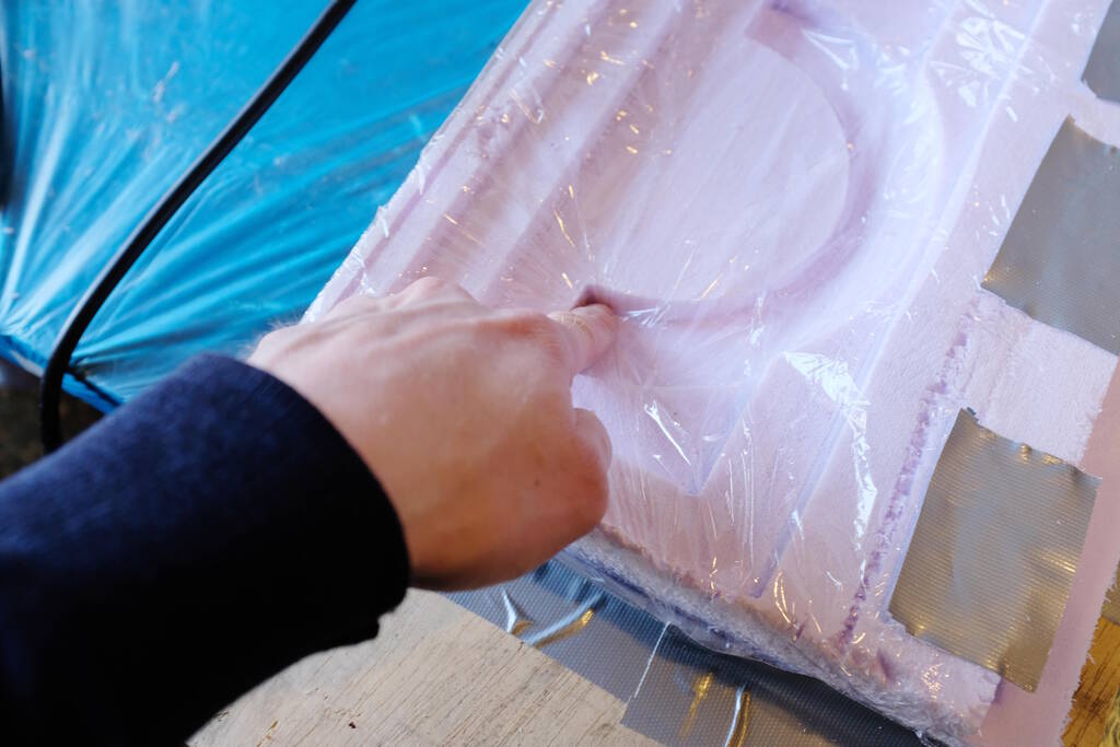
The shape is now quite complex, so I have to be careful to make sure that the foil is not too tight so the foil breaks if another corner is pulled down:
The top as well:
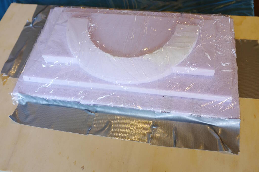
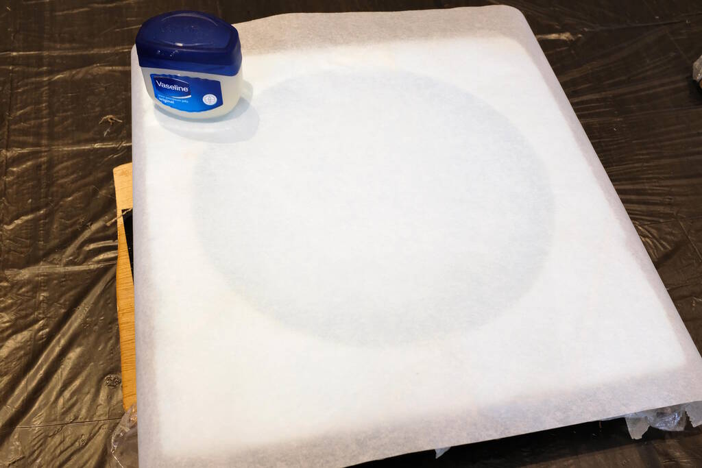
Adding Vaseline:
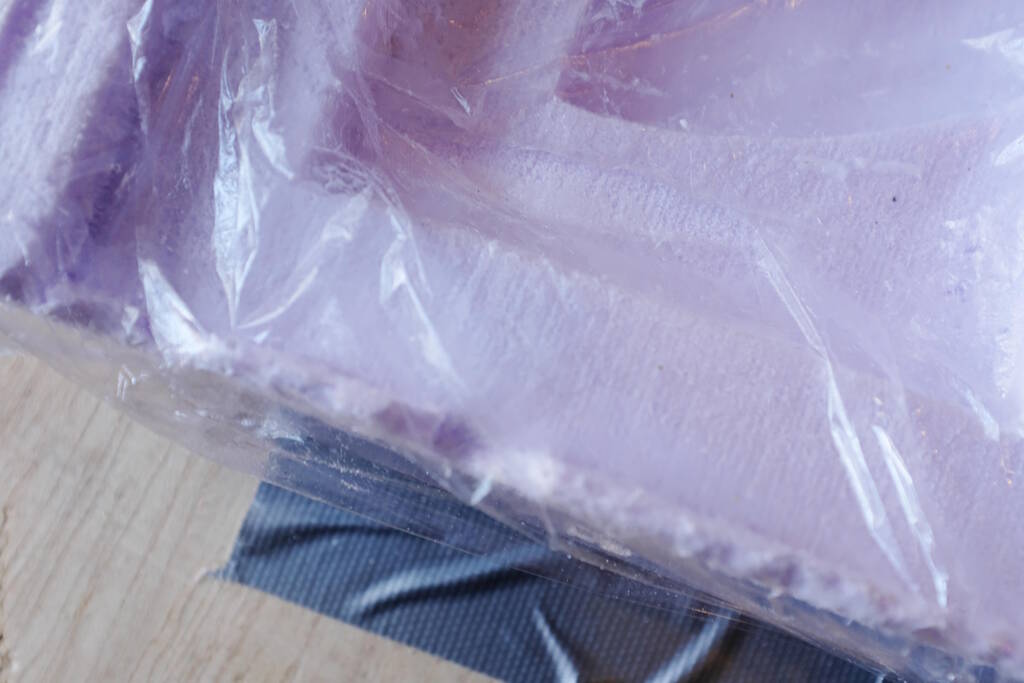
I accidentally ripped a part of the foil. I think this will potentially ruin the mold as soon as I get the material out:
I noticed that when I add parchment paper, it folds over the rim that I made. This will most likely make the surface uneven, so I decided to cut out a piece of parchment paper for the rim:
I prepared everything for soaking the linnen with the epoxy:
I turned on the ventilation:

And started mixing (three minutes of mixing and 11 minutes pot life):
I soaked the material:
I scraped all the material making sure everything was fully soaked and pressed in. I then carefully placed the three layers in the compartiment and finished it with an extra layer of epoxy:
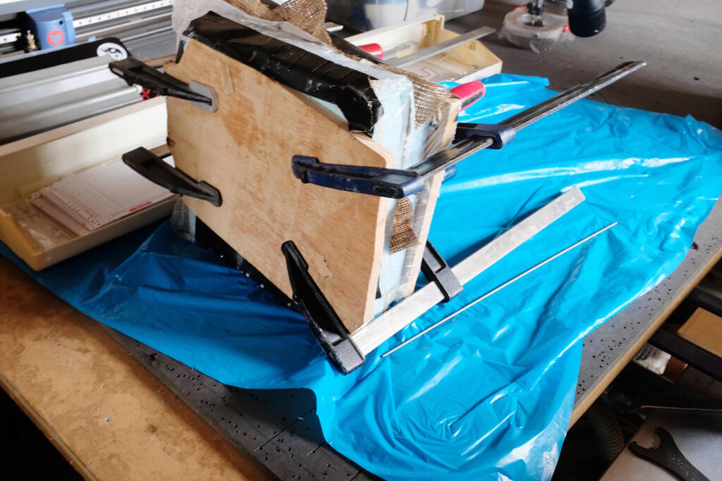
Closed the lid and compressed the wooden blocks:
Let's wait until tomorrow!
Acquiring the Object
The next day I separated the two pieces:
The top part came out well:
The gypsum appeared to be mor or less intact and didn't suffer from the exothermic reaction. The left side seemed a bit "wobly":
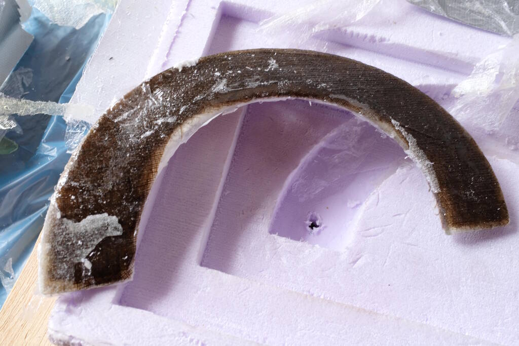
The cambered corner sitting in the bottom piece:
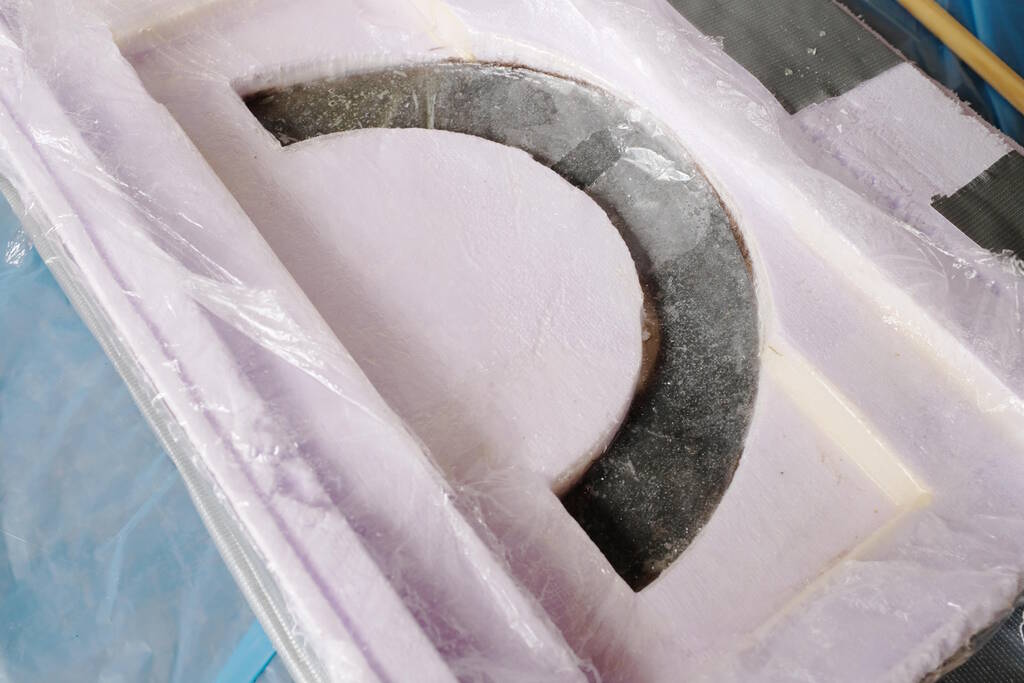
There is a whole thin layer of epoxy around:
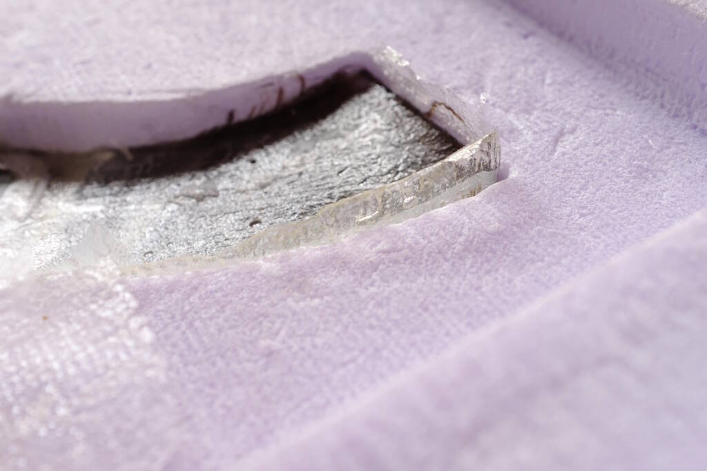
It was quite difficult to get it out of the form, but in the end it came loose:
I needed to push it out from the back side, making a whole and pressing against the piece:
This is the piece that came out:
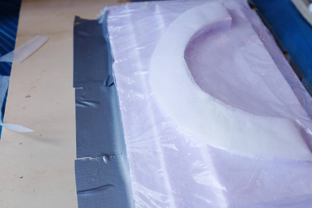
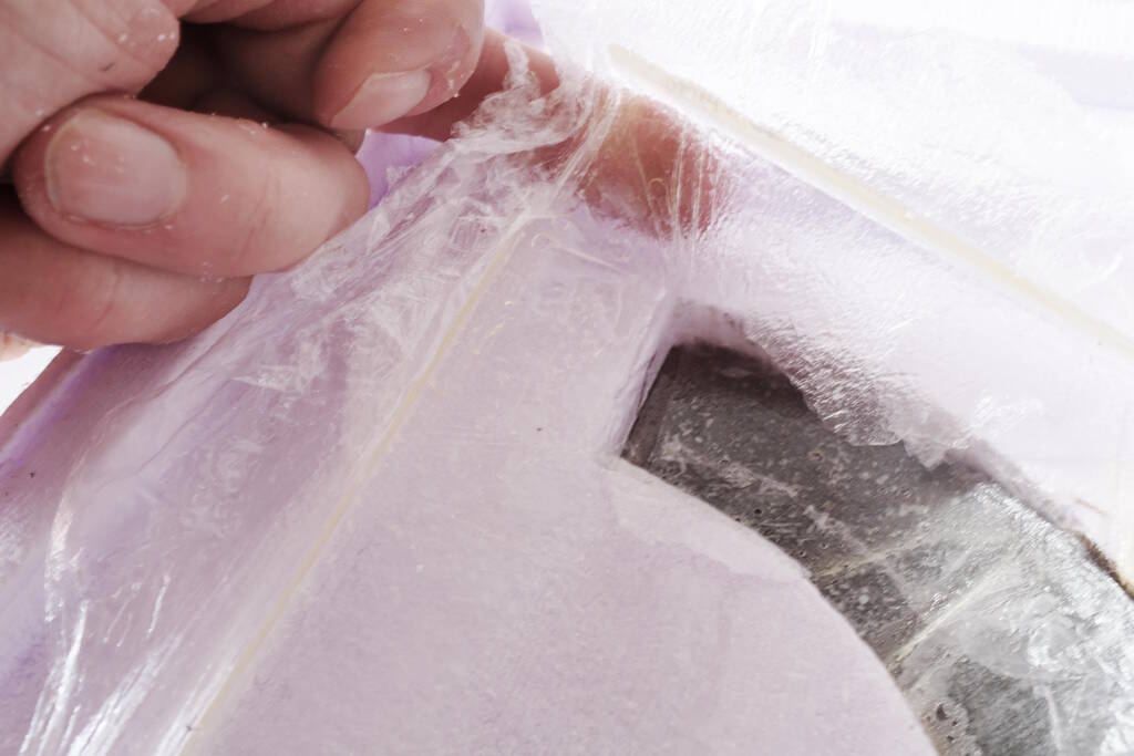
Removing the parchment paper:
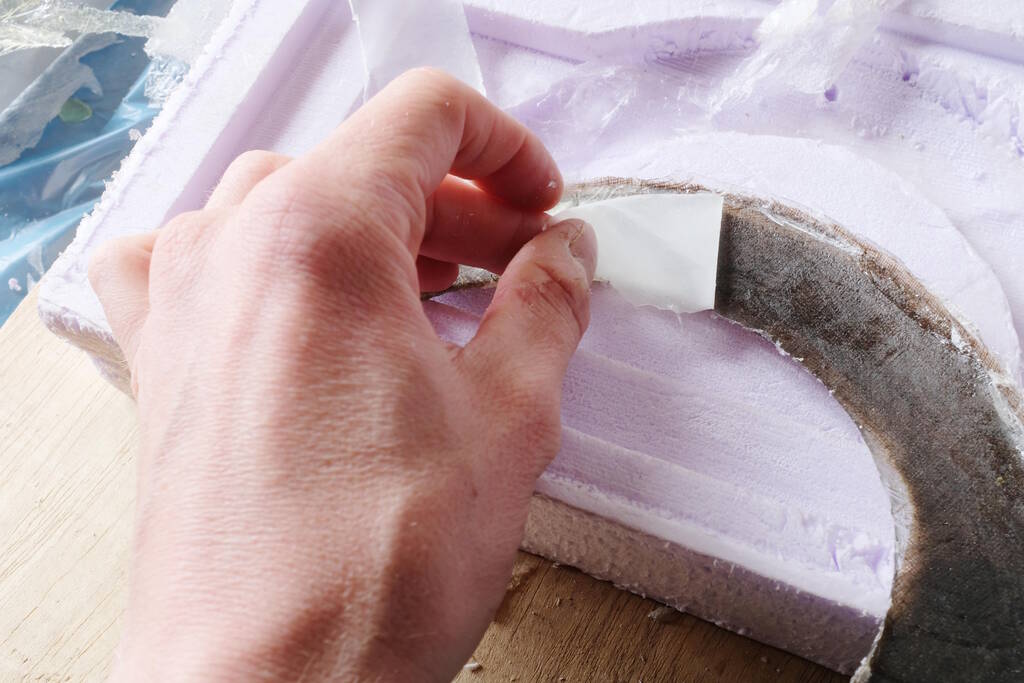
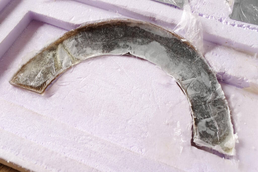
The result:
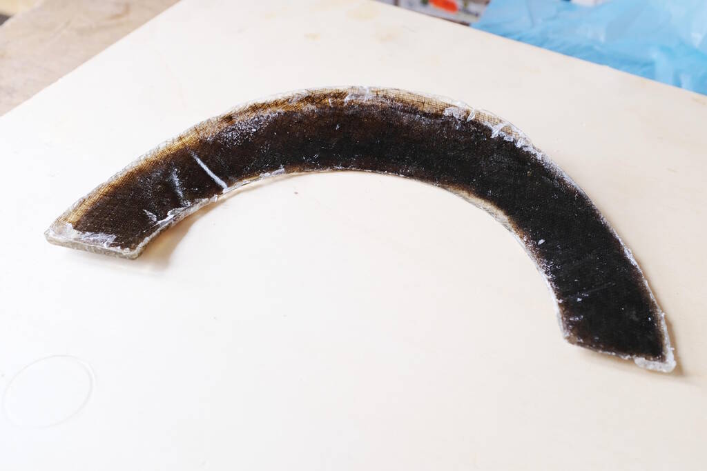
There are still thin layers and you see some folds:
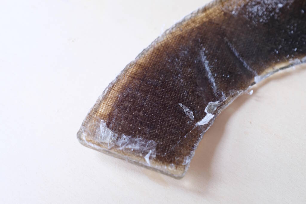
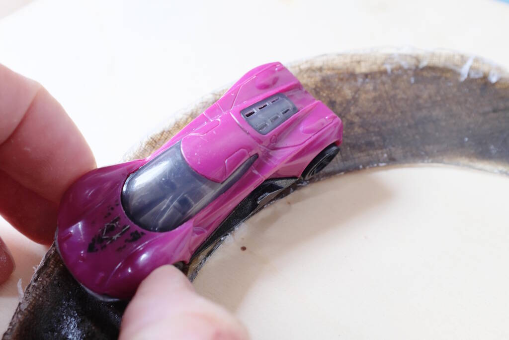
The U-turn is a bit small in dimensions for the car but the camber came out well:
Reflection
The surface is not as smooth as I would want it, but I think I could make this work in a next iteration, now understanding better how the object comes out. However, this process has been very elaborate and for my final project, quite some experimentation would be needed to find the proper dimensions, the right angle for the camber and the radius of the u-turn. As such, this process is not very suitable for my project and I think I can achieve a better result in terms of smoothness with applying flexures on wood.
For a second iteration, I would try to find a better way to design the mold around the model. This may be resolved with a better way to handle "deep" milling, perhaps with multiple layers of foam. Additionally, I would analyze how the skirt of the mill affects the foam. Finally, I would laser cut the pieces of fabric to get a cleaner result.
Tasks
Fab Academy
- Design something with a digital fabrication process not covered in another assignment.
- Document the requirements that your assignment needs.
- Include everything necessary to reproduce it.
- Demonstrate workflows in the used process.
- Select and apply suitable materials and processes.