Lecture Networking
Today is a national holiday (King's day) but we continued anyway. Erwin and Bas were there and Erwin gave a lecture on networking and communications. In my computer science study we never went beyond the bits, with hardly any attention for the physical layer, so in this lecture I could try to understand the physical layer as well. Below I summarized what I learned from the lecture.
UART
I think I should have known and I probably knew this at some point, but the baud rate is the number in bits including the overhead bits. In an earlier week, I had already realized that serial does not need a clock but that you need to agree on the speed of transmission. I didn't know about differential signals that have better resistance from outside influences.
SPI
I prefer to use the terms "main" and "secondary" and the devices connected by SPI don't have a receive or send port, but MOSI and MISO. This works as follows: For the main device , MOSI is the output ( Main Out Secondary In) and MISO is the input ( Main In Secondary Out).
For a secondary device , MOSI is the input (Main Out Secondary In ) whereas MISO is the output (Main In Secondary Out ).
Daisy Chaining is an interesting technique and suppose we have a buffer of 8 bits:
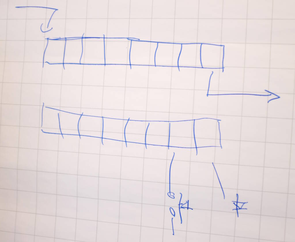
The top buffer is for receiving and sending and the bottom buffer is the device's copy, let's call it the "device buffer". If chip select becomes active, the device copies the receive/send buffer into the device buffer. If chip select becomes inactive, the device copies its buffer into the receive/send buffer. Each clock cycle a bit is shifted onto the line.
This mechanism ensures, that we can read from the network and write to the network based on pins that are connected to our buffer, for example a switch and an LED.
The clock is determined by the main device and this allows the main device to simply pause communication for a while. Sometimes it is necessary to mix signals between 3.3 and 5 V for example. This can be achieved by level shifters and SparkFun has devices for that.
Send Messages between Projects
Samson, Michelle, and I decided to analyze the serial communication with between two ESP32C3 and analyze it with the logic analyzer. Samson had the receiving ESP32 and Michelle the sending one. I would be in the middle analyzing the communication with the logic analyzer. This was the setup:
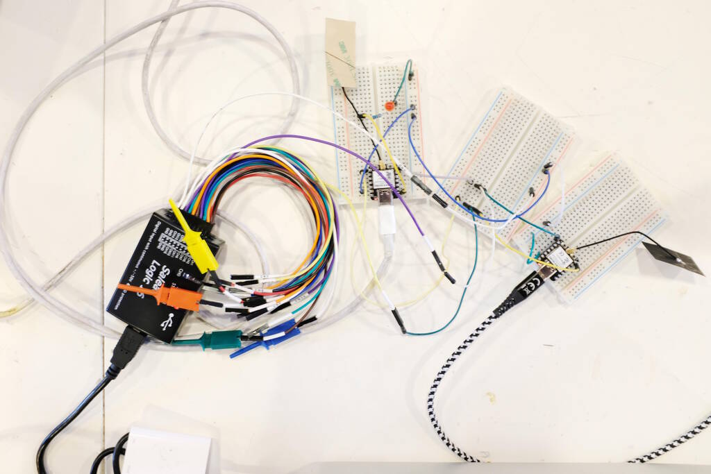
Michelle and Samson both had trouble uploading code to the microcontrollers, with Michelle getting null pointer exceptions in the Arduino IDE. We then decided to switch to Arduinos but while we could analyze the traffic coming from Michelle with the logic analyzer, Samson's device (an Arduino Leonardo) did not receive it.
As we were switching power sources, it turned out that somehow Michelle's communication was powering an LED on Samson's Arduino Leonardo (there was no other power source than the serial communication). This was the non-working setup:
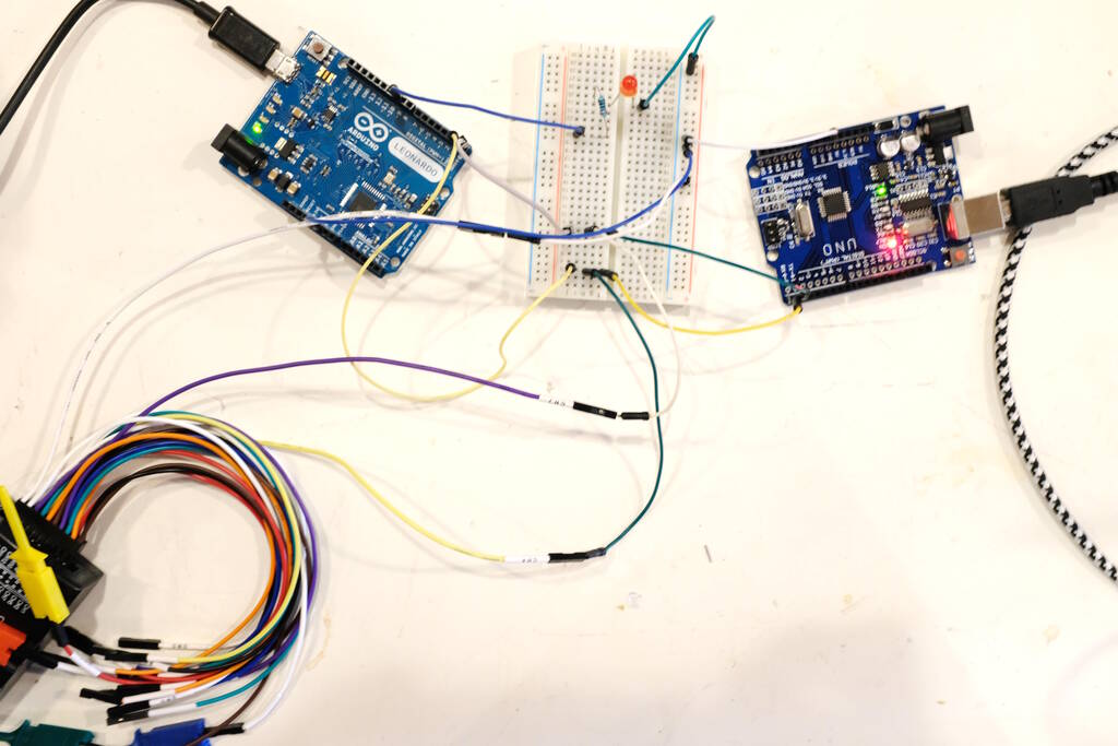
We then switched out the Leonardo for a different Arduino and then it worked:
Using the Logic Analyzer with sigrok and PulseView
We used the Salaea Logic16 device and I wanted to use sigrok with PulseView as GUI. Unfortunately, although the device was recognized, I couldn't connect to the device with PulseView.
I decided to install Saleae's proprietary software Saleae Logic and this allowed me to recognize the device. However, Henk told me that PulseView should simply work, so before actually using Saleae, I opened PulseView again and then it somehow worked.
After investigating, it turns out that sigrok needs firmware for this device and it provides a tool to extract it from the Saleae proprietary software. My hypothesis is that the Saleae proprietary software recognizes the device, uploads the firmware after which I can use it in sigrok. I think Henk at some point extracted this firmware and installed it in a place where sigrok can find it. The hypothesis is strengthened by the fact that each time I unplug the logic analyzer, I have to reopen the Saleae software to make it work in PulseView.
Setting up PulseView
In PulseView, you can press the "Configure Channels" to only show the channels that you attached to the logic analyzer. In our case, it was channel 4 and 7 (and ground, of course).
Uploading the code is visible on the logic analyzer as well:
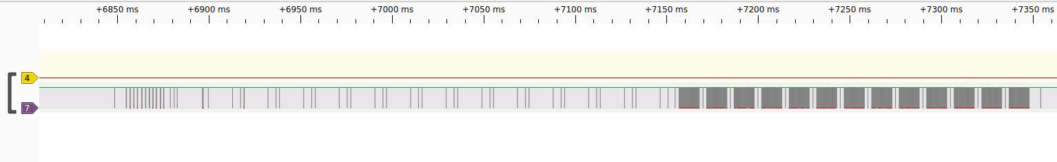
To decode UART, we can do the following: press the "Add protocol decoder" button which opens the "Decoder Selection" panel. Here we can search for UART and double click on it to add it as a channel. We can then double click the label to configure it with settings such as baud rate.
Recording the Sent Data
Michelle's device repeatedly sends the characters '0' and
'1', which should
translate to
0x30
and
0x31
respectively. The output for
sending '0':
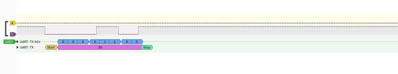
The output for sending '1':
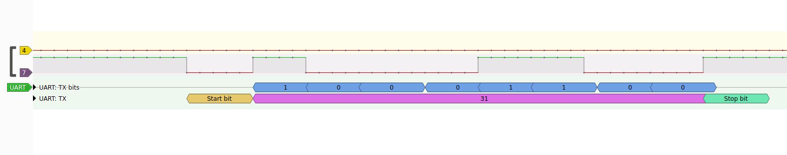
I'm a bit confused that PulseView doesn't use the convention to show
hexadecimal numbers prefixed with
0x
. In addition, I initially
didn't recognize that the bits are actually the bits sent in order, so you
have to read them from right to left, so we sent
0b00110000
and
0b00110001
, which is
0x30
and
0x31
in hexadecimal and
48 and 49 in decimal.
This communication was read by Samson's device that based on this turned on the LED as we could see in the video above.
ESP32 CAM
I decided to change my final project to a model car race track similar to what I built in week 3 but then from wood. The reason is that I foresee many difficulties with getting the water to my eyes and I would like to have something that moves in it, with a stepper motor or something. One of the ideas is to make a recording of passing cars and create a web application that streams this or builds a website for a particular run. Based on this, I decided to experiment with cameras and streaming.
Arduino Setup
I experimented with a breadboard and the AI thinker ESP32 CAM board. To
make this work in Arduino, add the following URL to Preferences
➜
Settings
➜
Additional Boards Manager URLs:
http://arduino.esp8266.com/stable/package_esp8266com_index.json
. In
Tools
➜
Boards
➜
Boards Manager, look for ESP32 and
update.
I wasn't sure which board I had with which exact pinout. I suspected that I had the AI thinker board, but there wasn't any mark on the board that confirmed this. This website allowed me to compare various pin layouts seeming to confirm that I have indeed an AI Thinker board.
So, in Arduino, I could select the AI Thinker ESP32-CAM board in Tools ➜ Board.
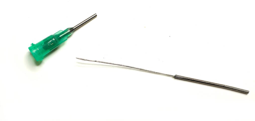
Programmers
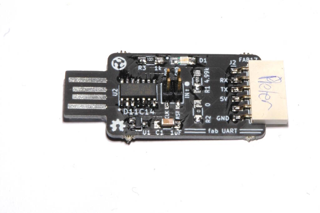
Since the Xiao boards have a USB-C connector, we don't need separate programmers so I did not have much experience with that until now. In the Bootcamp we soldered some programmers and I was looking for an FTDI programmer, but Michelle told me it doesn't really matter, and all programmers are essentially USB to serial devices. So, I used the following programmer from the bootcamp that I soldered myself:
Enabling Streaming
I followed this tutorial (until "Home Assistent Integration") and copied the code from Example ➜ ESP32 ➜ Camera ➜ CameraWebServer and modified it slightly for the pins and the network.
This simply worked, so I wanted to have a board for that. I later noticed that Neil used the exact same example in his networking class.
The Board with Microphone
I found out that the ESP32-CAM board doesn't have a microphone, but I would like to have audio as well, so I decided to add an I2S microphone. I used Neil's configuration from the Input Devices week but for some reason I erroneously concluded that the 4030D microphone that Neil used was not in the inventory anymore and instead I used the SPH0645 microphone.
I needed to make sure that the ESP32-CAM board had the correct pins broken out to use I2S. Fortunately, I read in the data sheet that I2S can be enabled on any GPIO pin.
Board Design
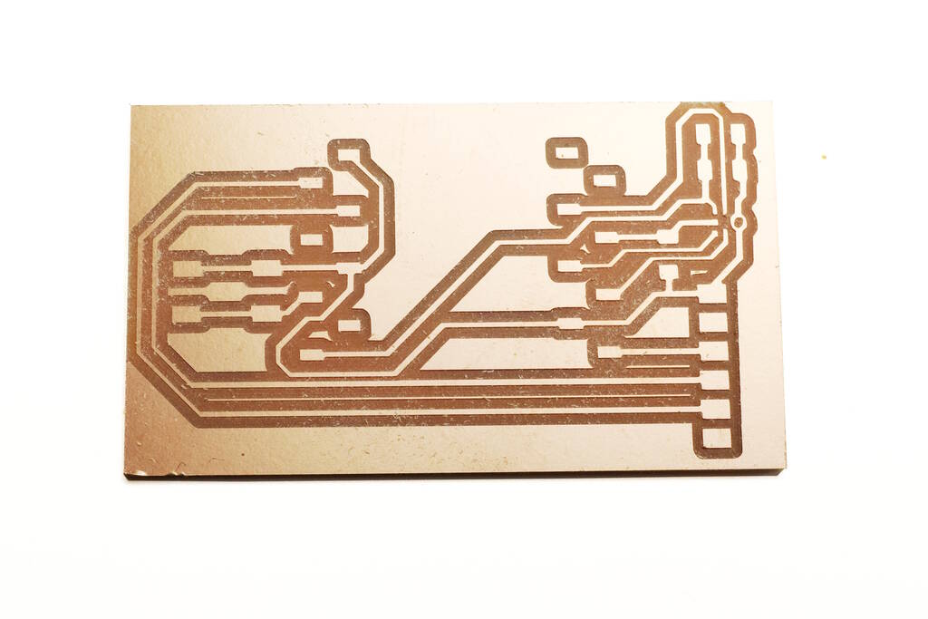
I made a couple of mistakes in the board design. I have two wires that pass underneath a resistor and to make that happen, the track needs to be less than 0.4 mm. Unfortunately, I only figured this out after I milled the board:
It turns out that the constraints have not been set up well in File ➜ Board Setup... ➜ Design Rules. In setting Constraints ➜ Minimum Clearance is not enough for these design rules to be checked. It is also necessary to set the Clearance and Track Width in Net Classes ➜ Default.
To solve this, I added a pre-defined size of 0.28 mm in Design Rules ➜ Pre-defined Sizes. For a particular track-piece that you want to be thinner, you can look up the properties (press E or right-click for Properties) where you can modify the track width.
The schematic that I used:

The Bill of Materials:
| Reference | Value | Footprint | |
|---|---|---|---|
| C1 | 200 pF | Capacitor_SMD:C_1206_3216Metric_Pad1.33x1.80mm_HandSolder | |
| C2 | .1 uF | Capacitor_SMD:C_1206_3216Metric_Pad1.33x1.80mm_HandSolder | |
| J1 | Serial | fab:PinHeader_1x06_P2.54mm_Horizontal_SMD | |
| MK1 | Mic_MEMS_Digital_SPH0645LM4H | fab:Mic_MEMS_Digital_Knowles_SPH0645LM4H | |
| R1 | 100 kOhm | Resistor_SMD:R_1206_3216Metric_Pad1.30x1.75mm_HandSolder | |
| SW1 | Boot | fab:Button_Omron_B3SN_6.0x6.0mm | |
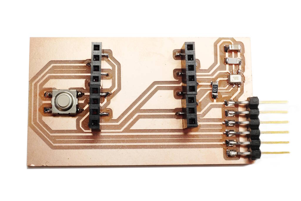
| U1 | ESP32-CAM | fab:Ai-Thinker_ESP32-CAM_SocketSMD |
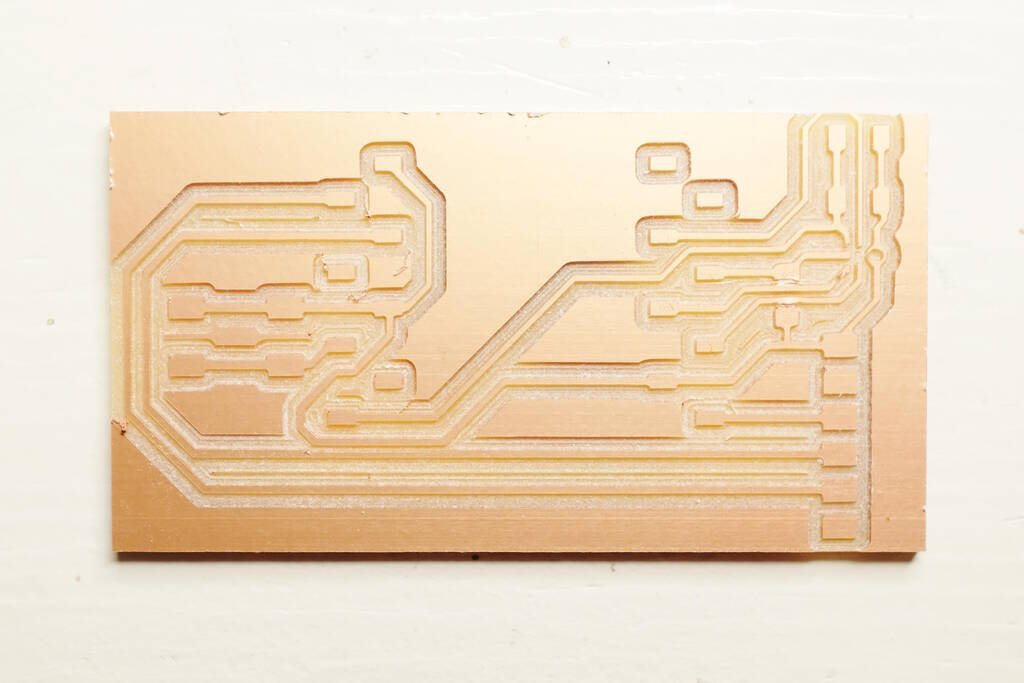
The PCB:

Notice the two wires that pass underneath R1 at the middle right. Additionally, I added the footprint of the ESP32-CAM myself to the Fab KiCAD repository.
Milling the Board
I still have issues with milling with the z-height. I zeroed on the front of the board, milling started 2 cm from the front of the board and milling is fine there. When the mill moves to the front, for some reason it cannot touch the board fully any longer and it starts engraving. I asked Henk and noted that Michelle removed a piece of paper inbetween the board and bed of the mill. Henk reinstalled the piece of paper and then the milling was fine. It seems as if the board is not completely flat. This seems to be a larger issue at the right side of the bed.
With this setup, I am able to succesfully mill a PCB:
Soldering the Microphone
Soldering the microphone did not go well. I need to use solder paste and this was my first attempt that blew off the cap of the microphone:
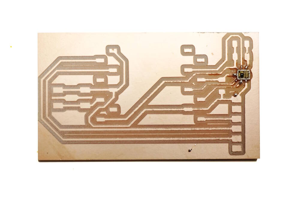
I followed a tutorial where the used 300 degree Celcius and I forgot to check whether this would work for the microphone as well. It turns out that it is too hot. One of the tubes of paste was clogged, so I used a new one and unclogged it immediately:
On this board, I2S seems to work by only get the value 0 as sample, so most likely this doesn't work.
The second attempt went better and I started with a temperature of 175 degree Celcius. Unfortunately not much happened with the solder paste so I increased the temperature step wise to about 270 (the maximum in the datasheet) and then suddenly the solder paste melted.
For this version I only read 1 as a sample and it seems as if VDD is bridged with the data line. However, I can't measure a connection between the two lines, so something else may be wrong.
The Camera Streaming
Streaming works:
To make this work, only minimal changes to the original Arduino example were necessary. For completeness, the diff with the original Arduino example.
$ diff --color CameraWebServer CameraWebServerOriginal/
diff --color CameraWebServer/CameraWebServer.ino CameraWebServerOriginal/CameraWebServer.ino
17c17
< //#define CAMERA_MODEL_ESP_EYE // Has PSRAM
---
> #define CAMERA_MODEL_ESP_EYE // Has PSRAM
24c24
< #define CAMERA_MODEL_AI_THINKER // Has PSRAM
---
> //#define CAMERA_MODEL_AI_THINKER // Has PSRAM
37,38c37,38
< const char* ssid = "********";
< const char* password = "********";
---
> const char* ssid = "**********";
> const char* password = "**********";
So, I only changed the SSID and password, and I selected the AI Thinker board instead of the predefined board.
Tasks
Fab Academy
- Send a message between two projects.
- Design, build, and connect wired or wireless node(s) with network or bus addresses.
- Explain the programming processes.
- Outline problems and how you fixed them.
Personal
- Getting the microphone to work.
- Creating a merge request for the ESP32 in the Fab KiCad library.
Files
The files contain the code that runs on the board, the design of the board, the two footprints for the ESP32-Camera boards for KiCad library files. The symbols in KiCad libraries are not stored as separate files but are stored in one big file. Therefore, I included a diff with the Fab KiCad library. My plan is to create a merge request for the Fab KiCad library to have it included.