Lecture Molding and Casting
Introduction Molding and Casting
Saco and Henk gave us an introduction to molding and casting, a subject I've been looking forward to since the beginning because I have no experience with this whatsoever.
Saco started to explain about sand casting that is still often used. For example Mitshubitsi creates turbo chargers with sand casting. We're not going to do injection molding where you use the pressure, but casting.
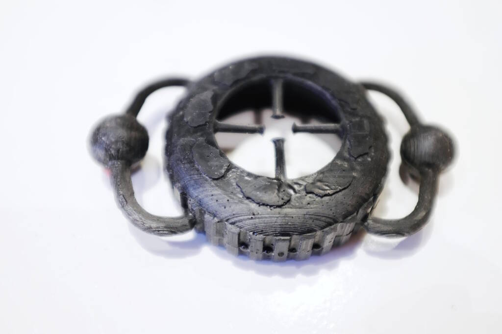
Saco showed some of his work and he created a rubber tire:
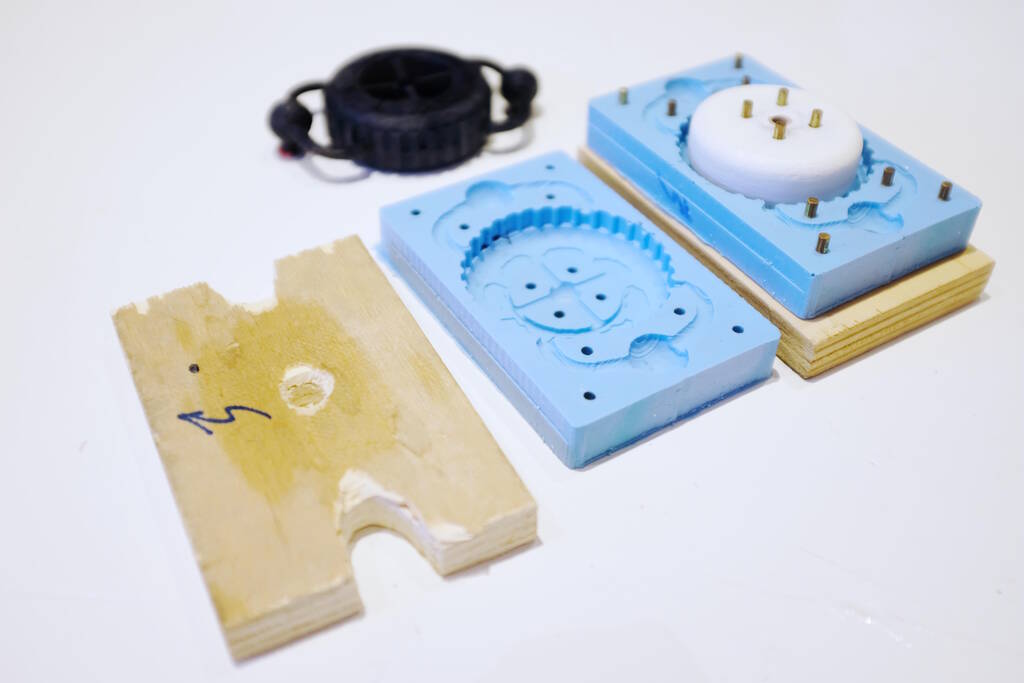
The molds, the inside core and the two wooden plates that press everything together:
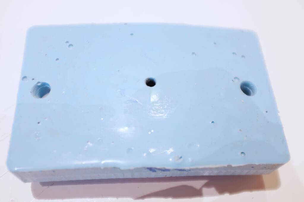
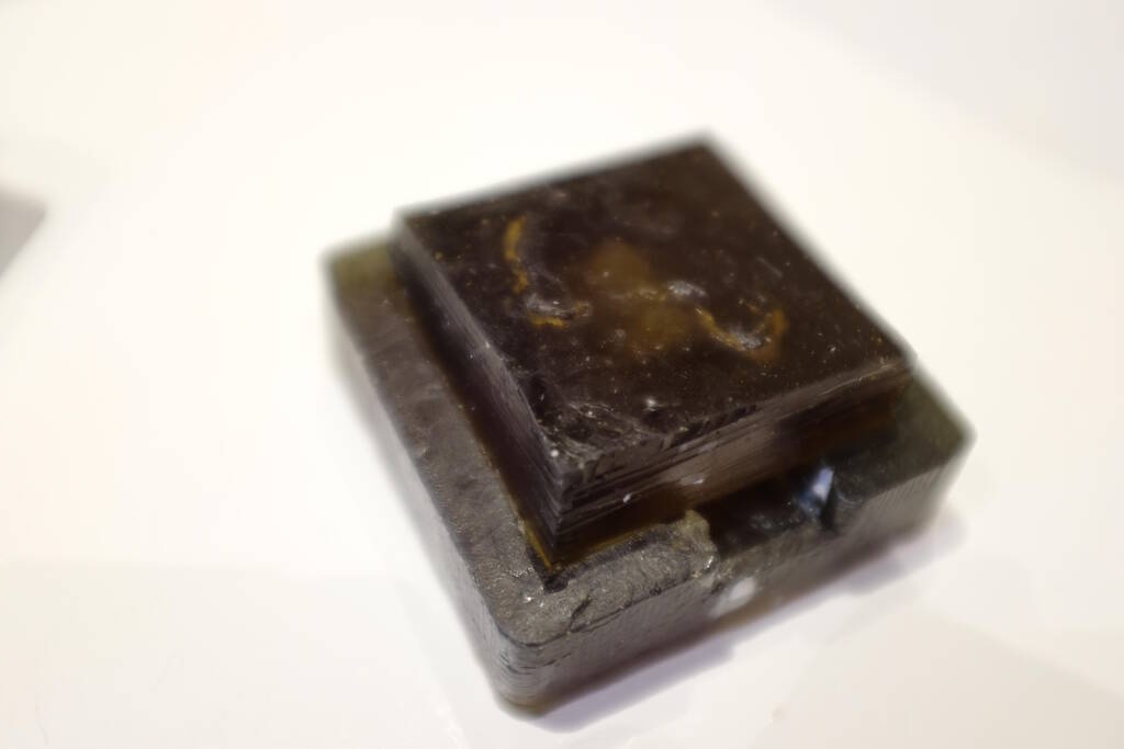
An example of the wax positive mold from another project:
Some terms: we are dealing with positive model that you get from a negative mold . There are blind risers and open risers that allow the material to expand. The open riser is good to have to be able to verify whether you have enough material and it is good to have vents .
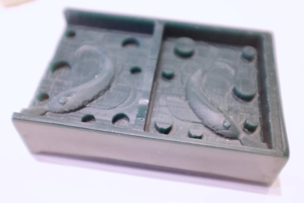
In the middle you see a vent and on the two sides there are holes to pour the material:
There are pins to align the two pieces but you can also design the mold for good alignment:
You have to take into account the viscosity of the casting material and and also whether the material is exotherm . Most materials are exotherm except for silicones and you have to take into account volume as well. A large volume produces more heat, accelerating the curing process, creating more heat, etc.
Another important factor is the draft angle or lossingshoek in Dutch. This is a problem for fixed molds and less of a problem for flexible molds. A rule of thumb is that if the endproduct should be soft, you use a hard mold and vice-versa. Sometimes it is useful to use ejectors or uitwerpers in Dutch that allow you to push out the end product.
Another thing to take into account besides volume is surface area: If the material has to flow over a large distance, for example a long piece, you need to give it time to get there and you may risk that the material doesn't reach well.
The workflow is roughly as follows: You design something in 3D. Then you create a positive mold around that in. This positive mold has pins, vents, and blind and open risers, etc. You will CNC mill this positive mold in a block of wax. From this positve mold, you create a negative mold. This negative mold is used to cast the end product.
Milling a Block of Wax
With the CNC mill you will create a rough cut and then a fine cut in a block of wax. This is essentially for saving time and it may be possible to use the same milling bit for both tasks. An important point from Neil is that you first select the tool for milling and then create the design based on that. The longer the tool is, the more force is exerted on it, making it potentially imprecise.
Measuring the Block of Wax
Before we fixate the block of wax, it is a good idea to measure the block of wax:
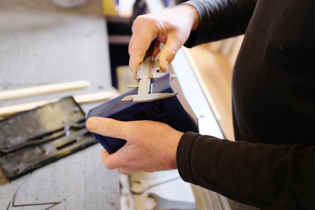
It is good to take multiple measurements of the Z to find the minimum and flatten that later with the CNC. The blocks of wax are recycled from old flakes of wax and the blocks are likely not to be straight in any way. For example on the block above, the Z was 38.55, 40.80, 38.50, and 39.90.
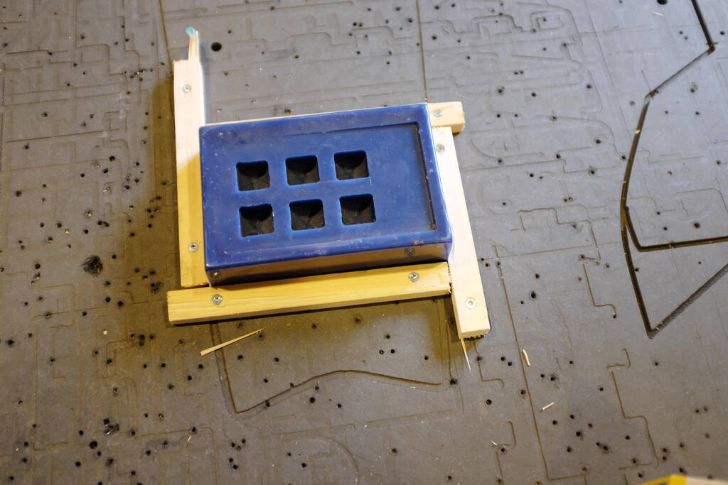
Fixating the Block
After we sand the sacrificial layer to make sure there are no screw holes that make the surface uneven, we use double-sided tape to fixate the block of wax to the sacrificial layer of the CNC:
For the shear forces, we fixate the block to the sacrificial layer with four bars of wood, making sure the block can not move in the x or y direction:
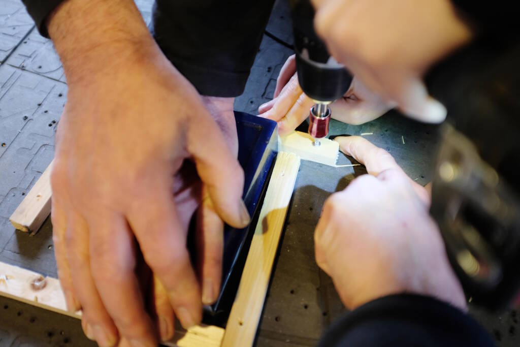
We use a "star" form:
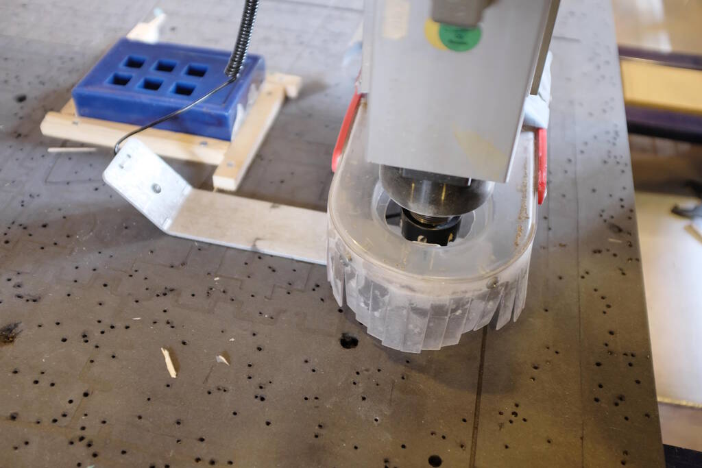
Setting up the CNC Mill
We zero the machine:
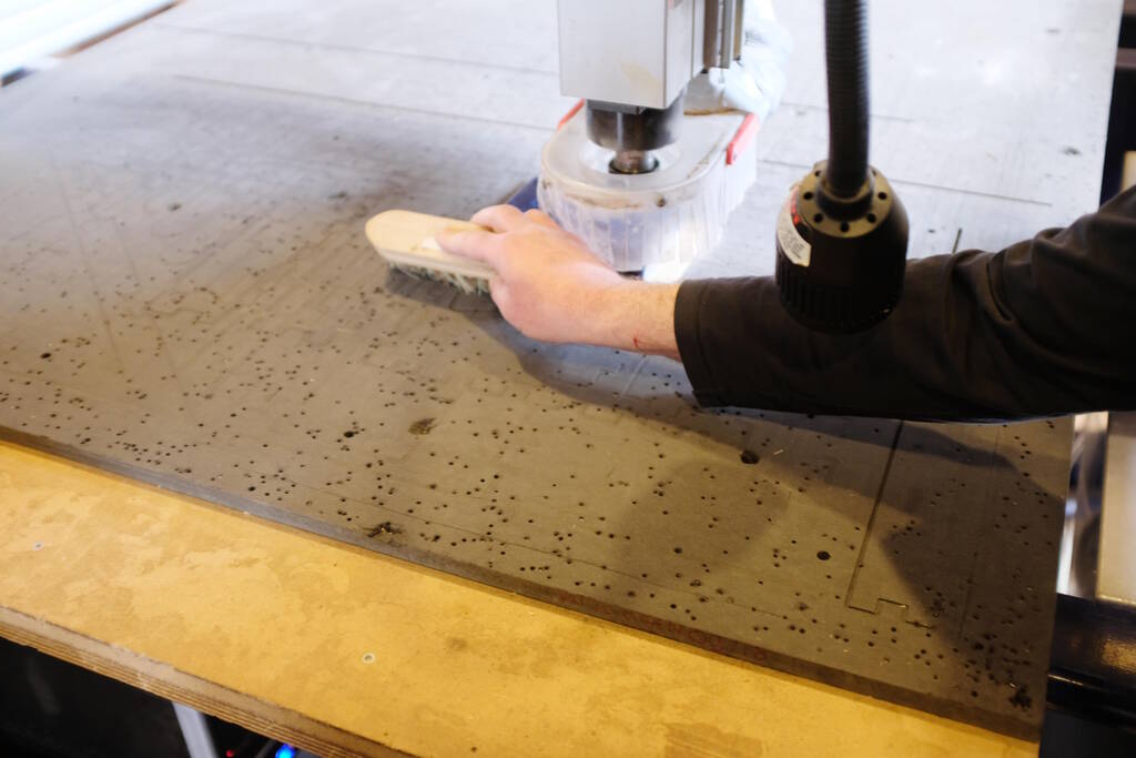
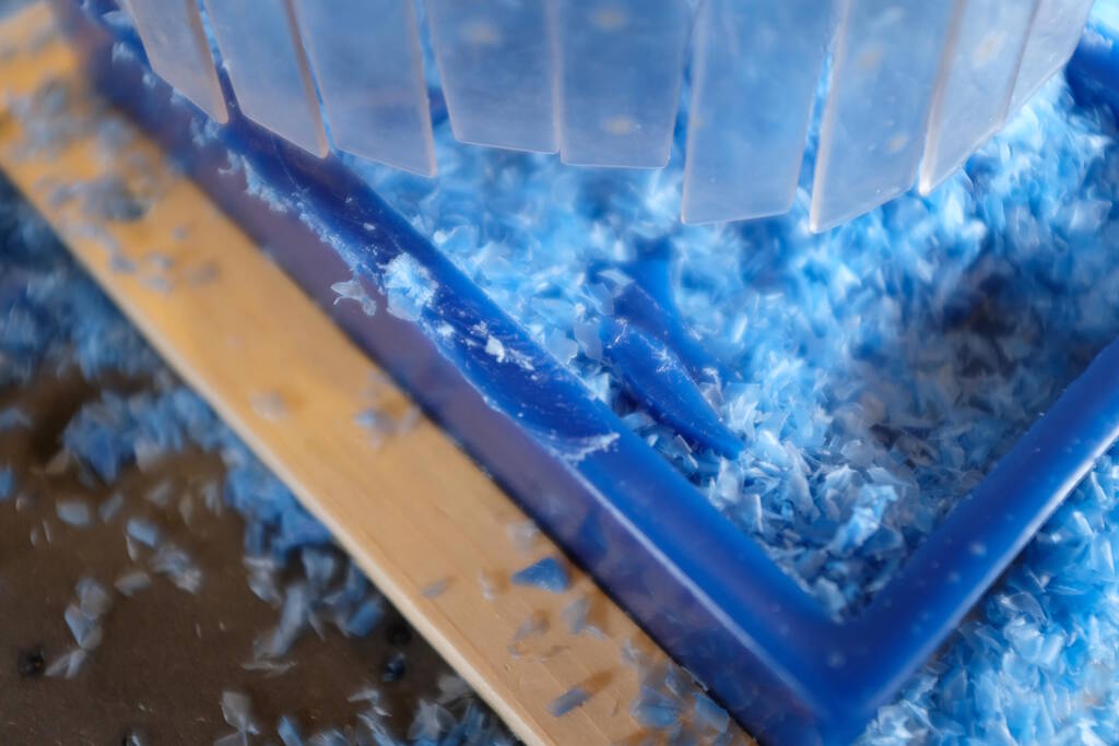
And we remove all the dust and other dirt from the sacrificial layer as this prevents other material to mix with the wax shredded pieces that we want to collect later. These pieces will be reused to get new wax blocks:
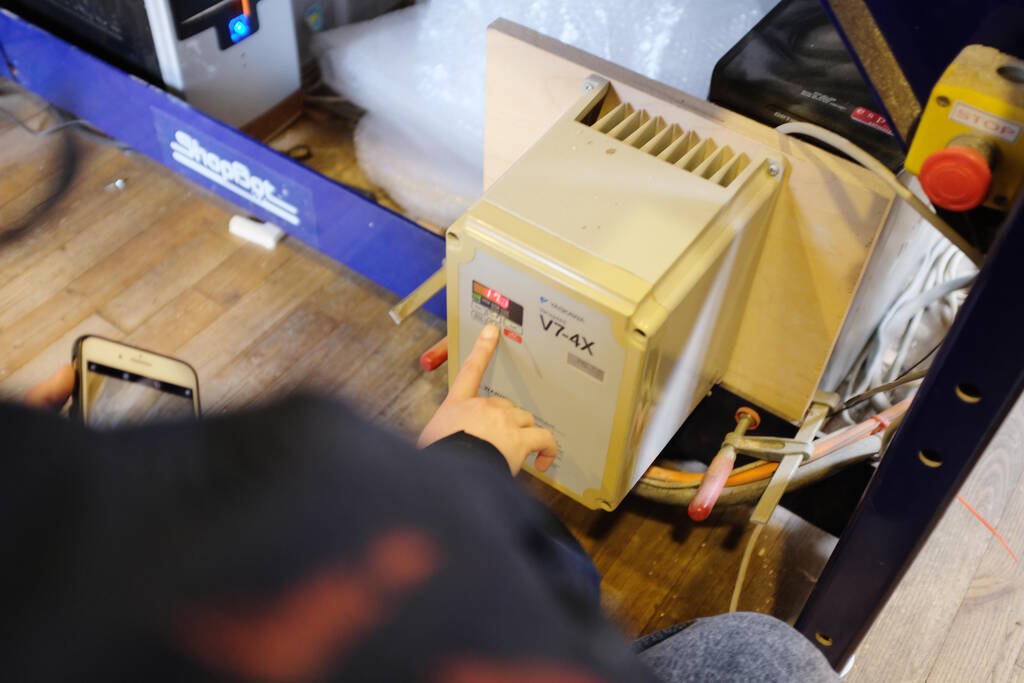
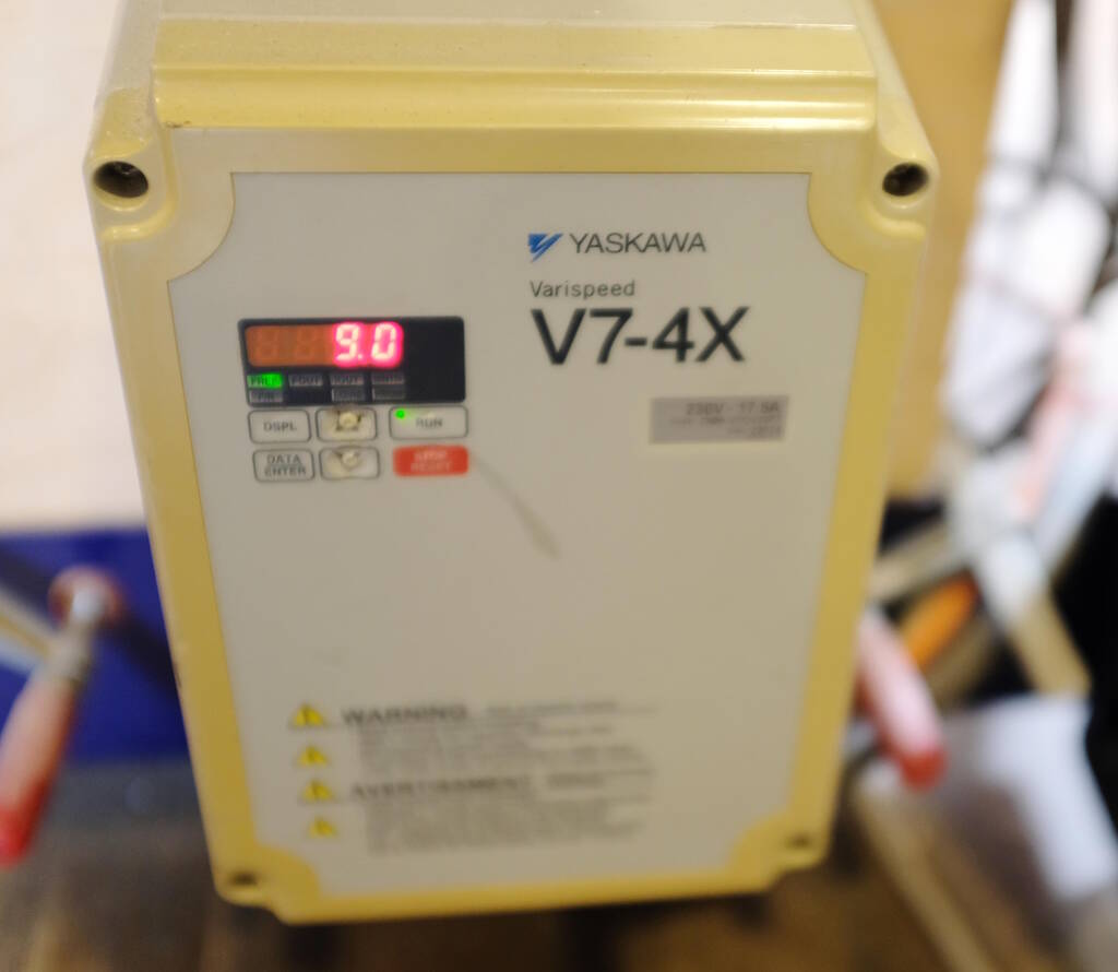
We also set the spindle RPM to a lower number, more suitable for wax, in our case to 9000 RPM:
VCarve Setup
Michelle created a small design as a test case for the block of wax we had. Setting up VCarve is quite complicated. We start with a new file and provide it with the dimensions of the model we use. We then import the model and modify the orientation. The Z-position of the model may not be right and we are going to fix that in "Material Setup".
Picking a milling bit depends on the smallest radius of your model. In our case, the smallest radius was 2.5 mm. In principle, this means that we can create such radii with a milling bit with a diameter of 5 mm, but as a rule of thumb it is better to choose a milling bit with a smaller diameter, for example 4 mm.
There are two roughing strategies available: z-level, which is essentially a strategy that slices. The 3D raster strategy follows the profile. Which strategy to choose depends on the model. If you have curves in the Z direction, you may want to use 3D raster. In general Z-level is good enough for rough cuts. We prefer the raster Y strategy because with this strategy only the head has to move and not the whole Y-axis.
The pass depth for a rough cut can in principle be set to 1 time the diameter of the tool (so 4 mm in our case) because wax is soft. The stepover can be set to a low value of 20% because wax is easy to process. We chose a pass depth of 2.5 mm because this allows us to flatten the surface on the machine (for which we chose a value of 3 mm). This can be set up in "Model position in Material".
The spindle speed can be set to 9000 RPM because dissipating the wax slivers is not that critical. The feed rate depends on that as well and we chose a value of 60 mm/s. We chose the plunge rate as 30 mm/s.
Milling the Block
To mill this small piece, we moved the head to the corner of the block of wax. Since we were only doing a test case, we did not record the absolute coordinates, but simply set the coordinates to the job coordinates and started milling:
The result:
We were not completely happy with the level of detail but it good to understand what comes out with the settings that we had.
Introduction to the Materials and Equipment
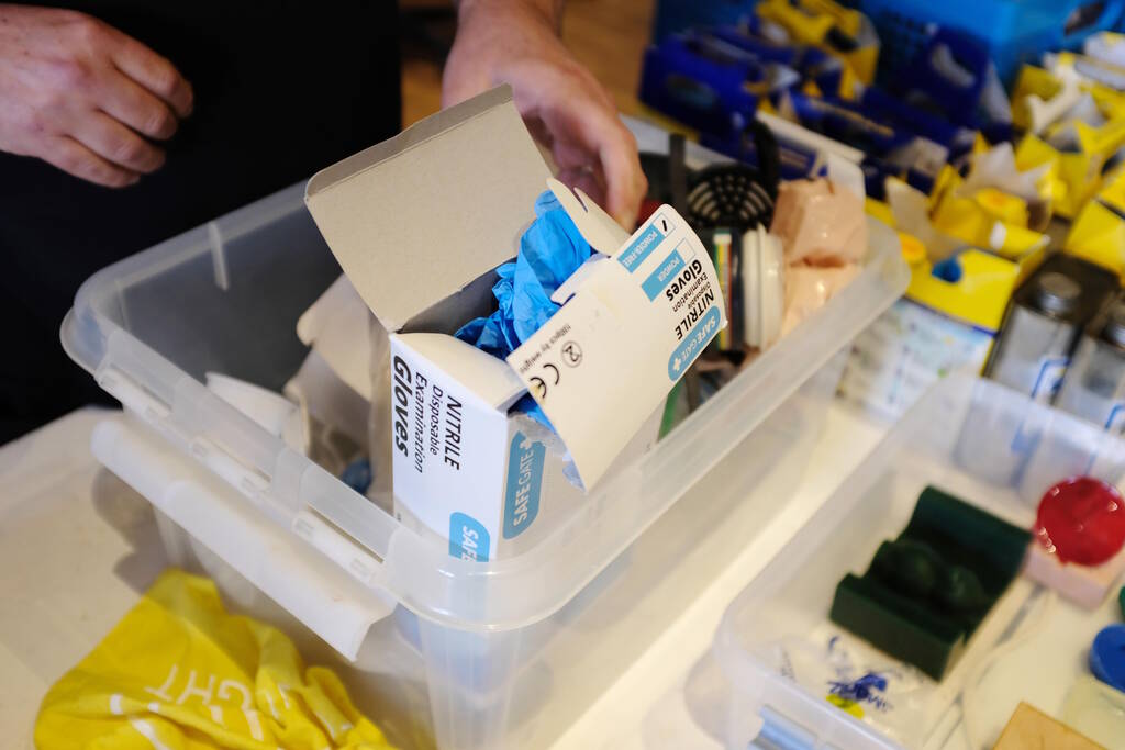
Saco and Henk gave us an introduction to the materials that we have at our disposal to do the casting and molding. We have boxes with gloves, other safety equipment, and other appliences such as cups and pieces of wood to stir.
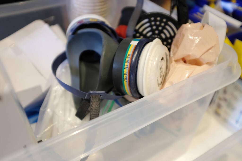
The vacuum pump and accessories to degass casts:
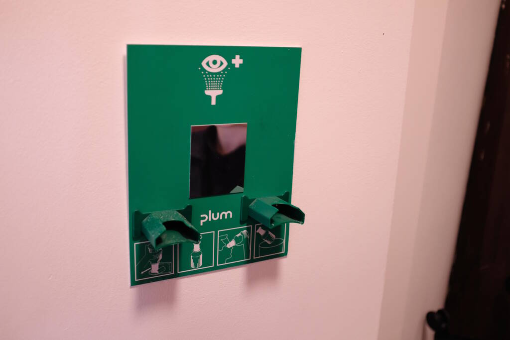
We have something to clean the eyes as well, but it is currently not loaded with the required capsules:
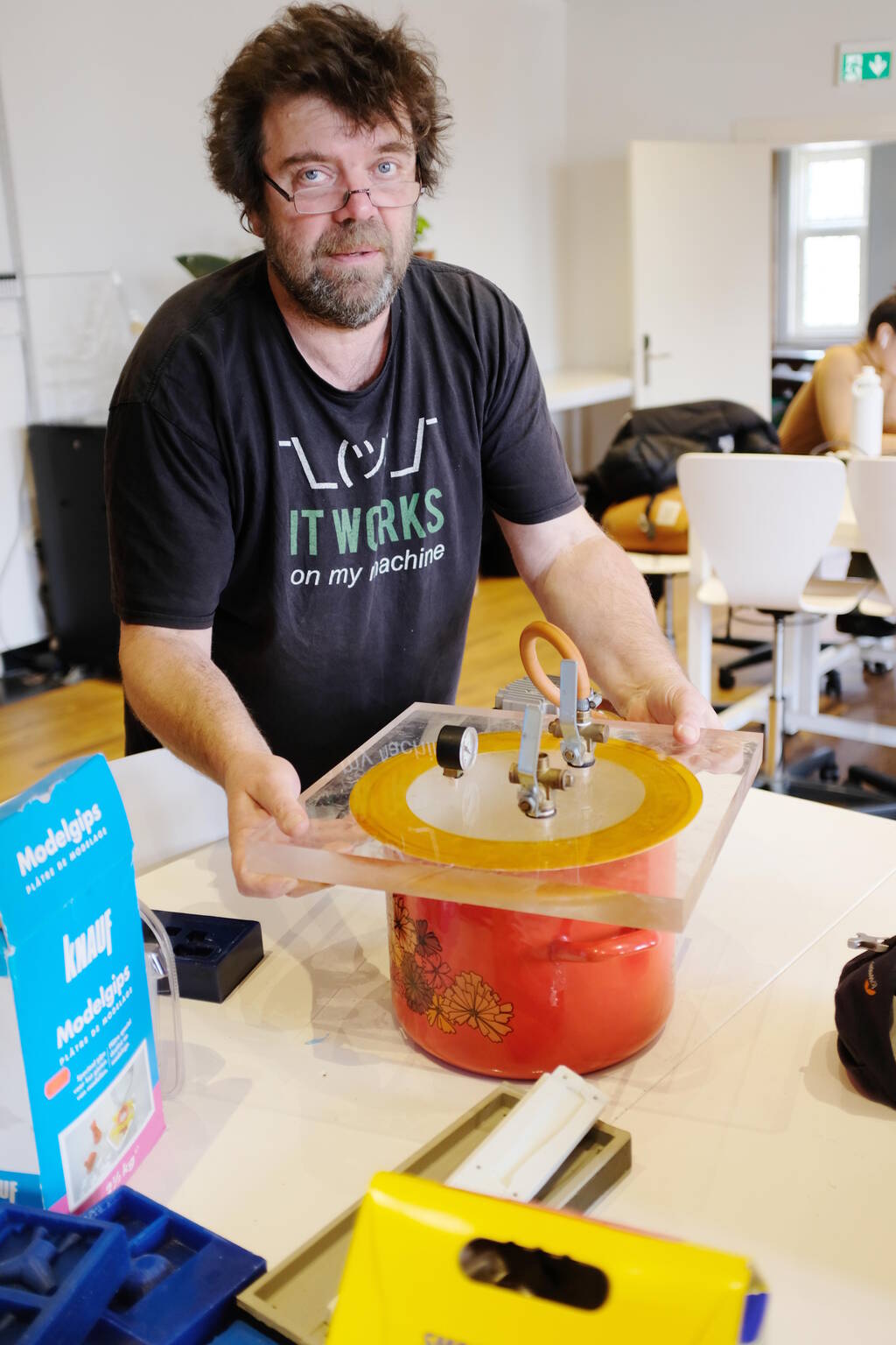
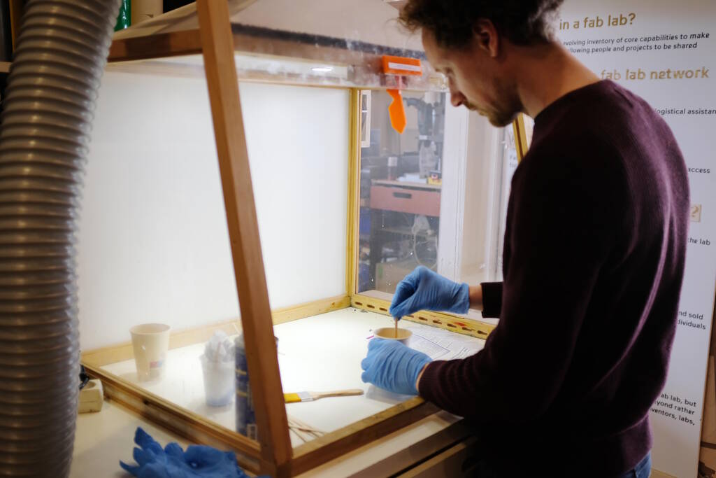
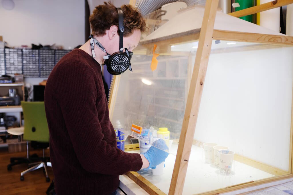
We also have an air filtration system, so if the datasheet mentions a well-ventilated room, we can use the following set up:
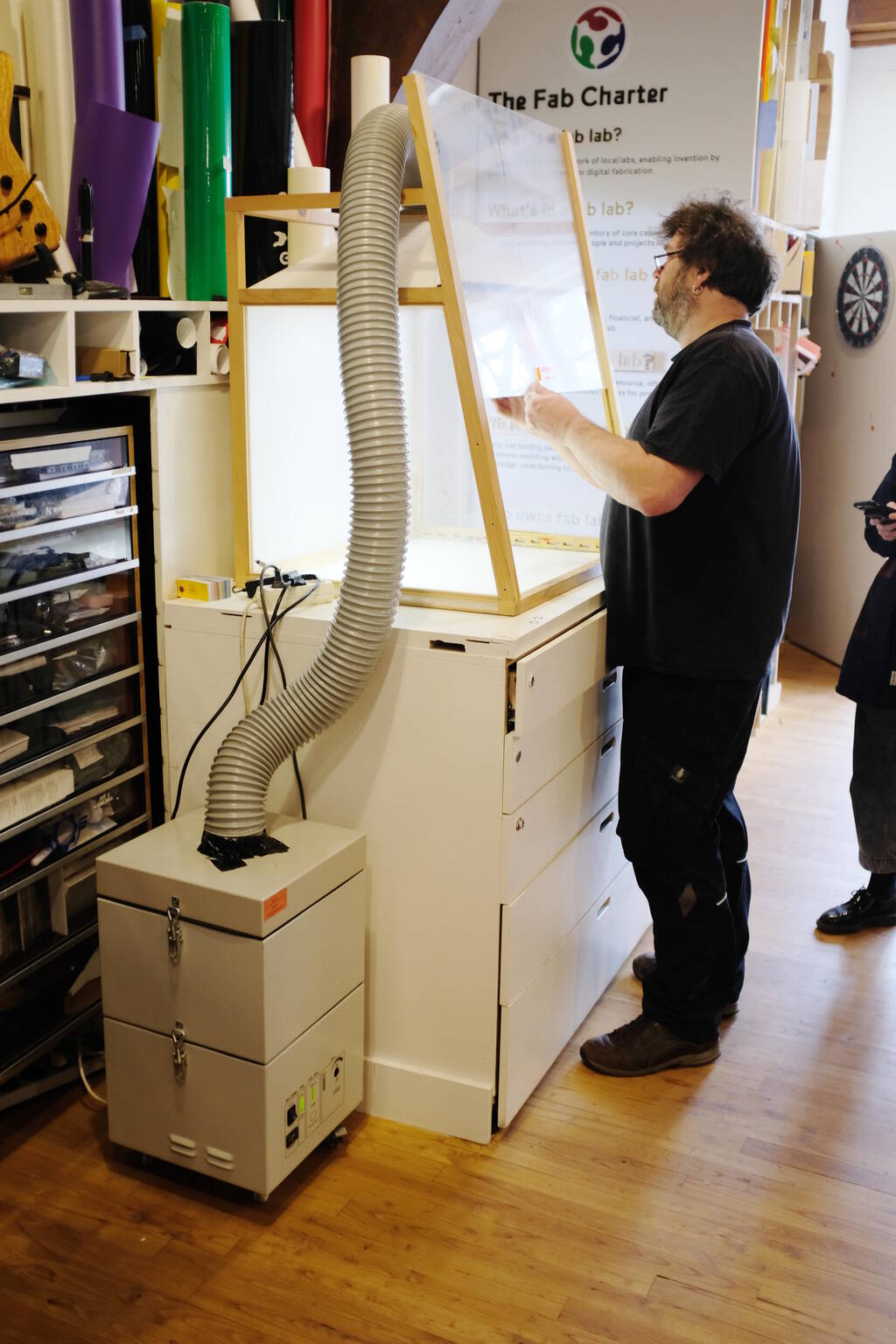
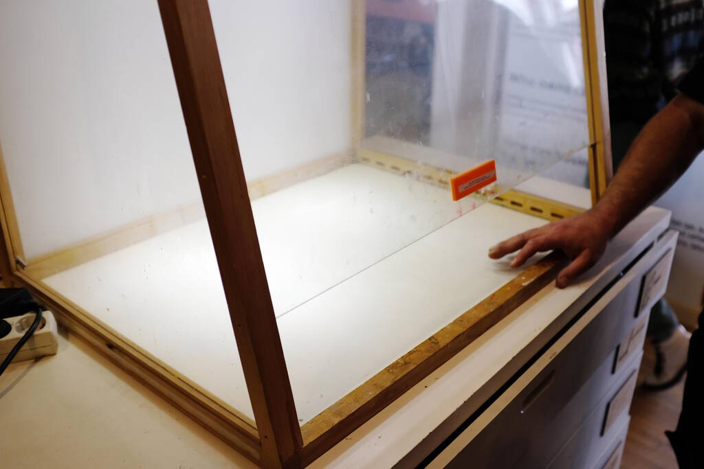
You can close the lid for your hands to enter:
The air filtration system operating:
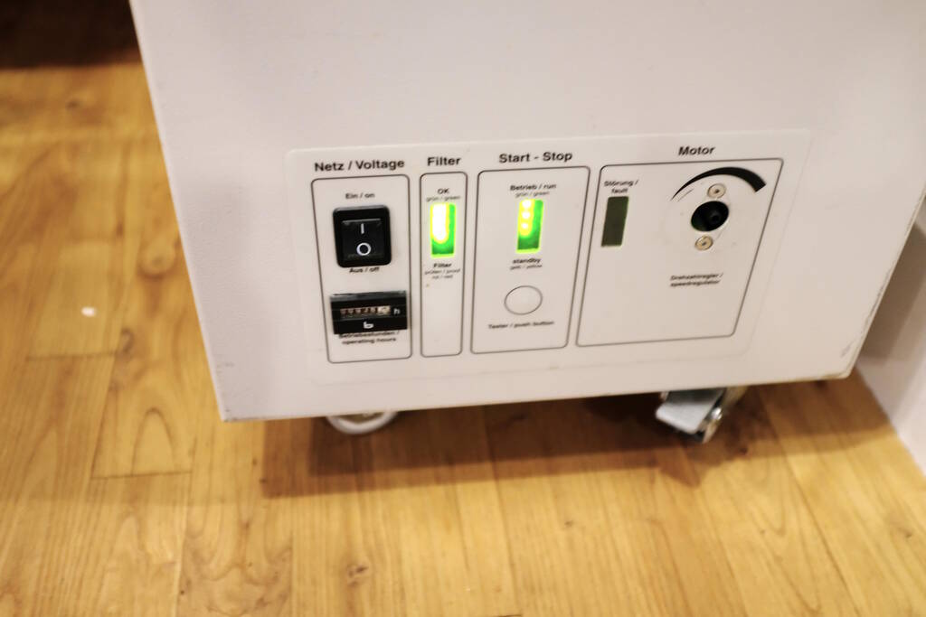
Henk tried to show us that quite some air is filtered per minute:
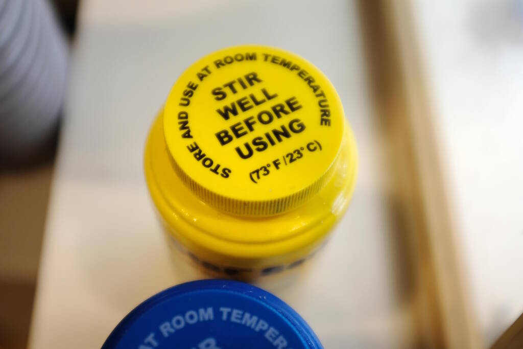
We have various materials to our disposal, for example this Smooth-Cast 305. It is important to note that most have two components that we typically mix in cups and the relative quantities can be measured in either volume or weight and sometimes both (not necessarily in the same ratios).
Other important notes are that we have mold release that we can spray lightly after which we make sure that it reaches all the parts with a soft brush. We can also color the materials if needed. The materials have a Shore number that defines how stiff the material is, a higher number is stiffer, so Smooth-Cast 305 is very hard material, whereas Ecoflex 30 is a soft, flexible material.
Review Safety Data Sheets
The Safety Data Sheets are important, but it is also good to understand that they are written from an American perspective with a very strong litigation culture.
I read the Safety Data Sheet of Smooth-Cast 305 and this was a quite interesting read because the material is not without hazards.
Firstly, these materials were used in previous years and the first thing to note is that the Safety Data Sheet that was in the box of Smooth-Cast 305 was not the correct one. So, this is the first thing to assure yourself off: Do you have the correct safety data sheet. It is most likely best, to simply look it up online.
The hazards are coded with the GHS system such as "H315" which means "Causes Skin irritation". Besides this mnemonic, there is a category number between 1 and 4 where 1 means that it is most dangerous.
Here the table of this material's hazards:
| GHS code | Description | Category |
|---|---|---|
| H315 | Causes skin irritation. | 2 |
| H317 | May cause an allergic skin reaction. | 1 |
| H320 | Causes eye irritation. | 2B |
| H332 | Harmful if inhaled. | 4 |
| H334 | May cause allergy or asthma symptomso or breathing difficulties if inhaled. | 1 |
| H335 | May cause respiratory irritation. | 3 |
| H351 | Suspected of causing cancer. | 2 |
| H373 | May cause damage to organs (Olfactory organs) through prolonged or repeated exposure (inhalation). | 2 |
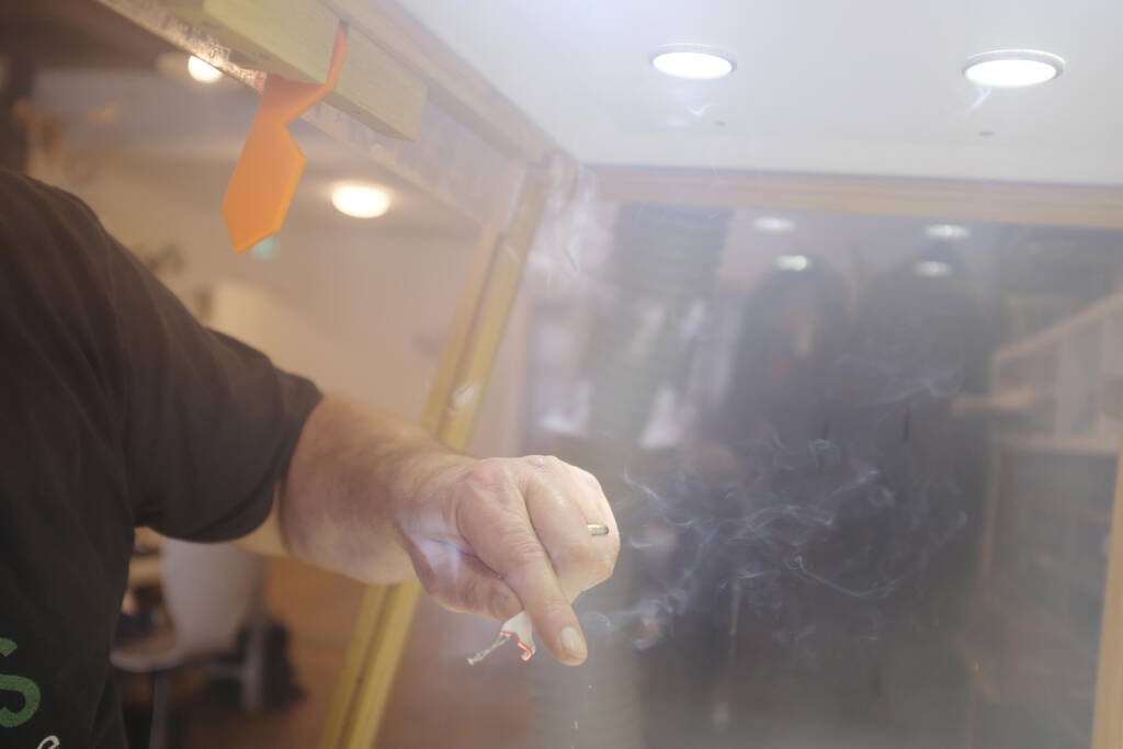
The recommendation is to wear liquid-tight gloves such as butyl rubber, neoprene or PVC, eye protection with side glasses. No additional clothing is required but it is recommended to have an ey bath and safety shower. Additional comments are to never eat, drink, or smoke in work areas.
A final interesting note is that the safety data sheet is split up in a part for either compoment. So, the hazards above applied to component A, but component B did not have hazards listed.
I also read the Safety Data Sheet of model gips but it was not hazardous.
Testing the Materials in our Lab
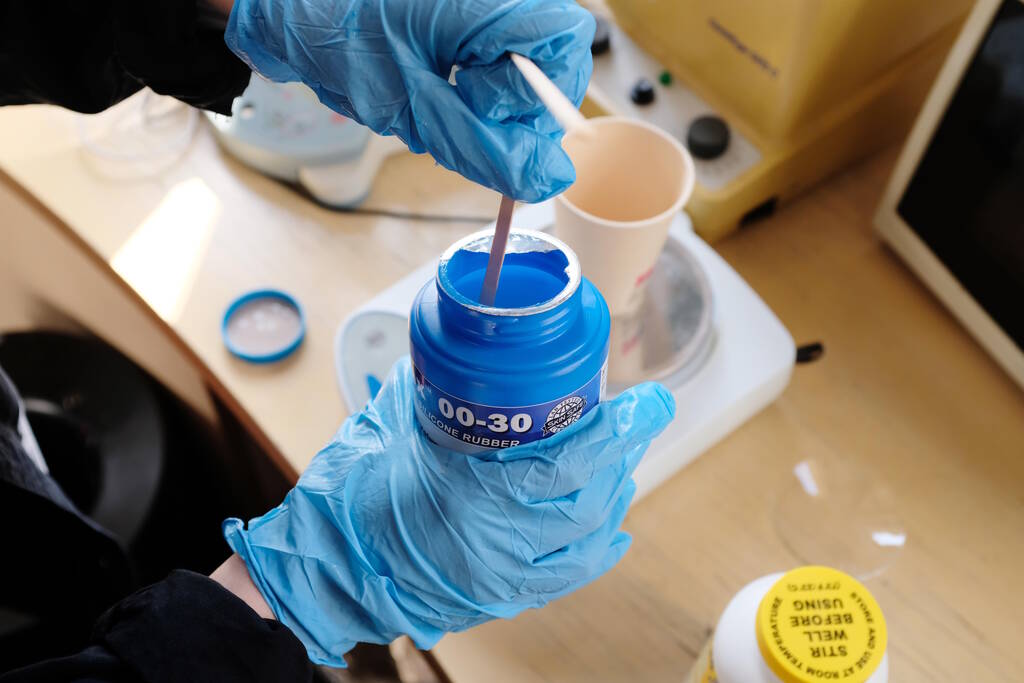
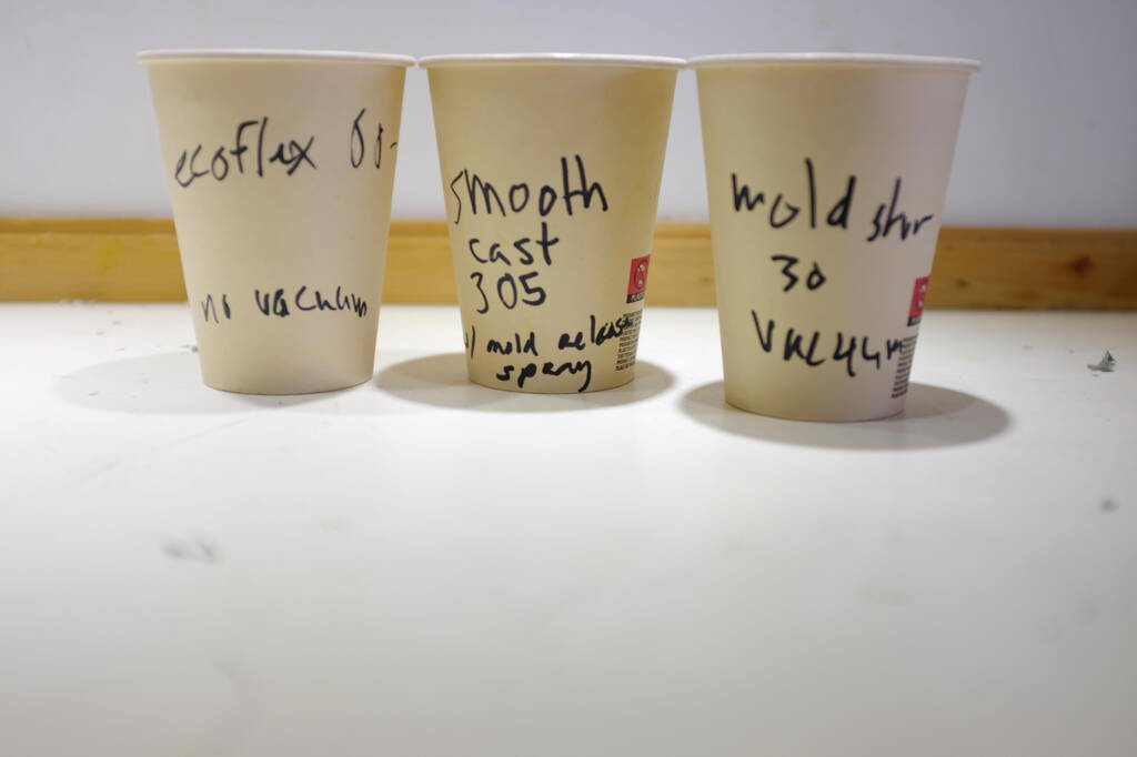
We tested three materials: Mold Star 30 using a vacuum pump, Ecoflex ... and Smooth Cast 305.
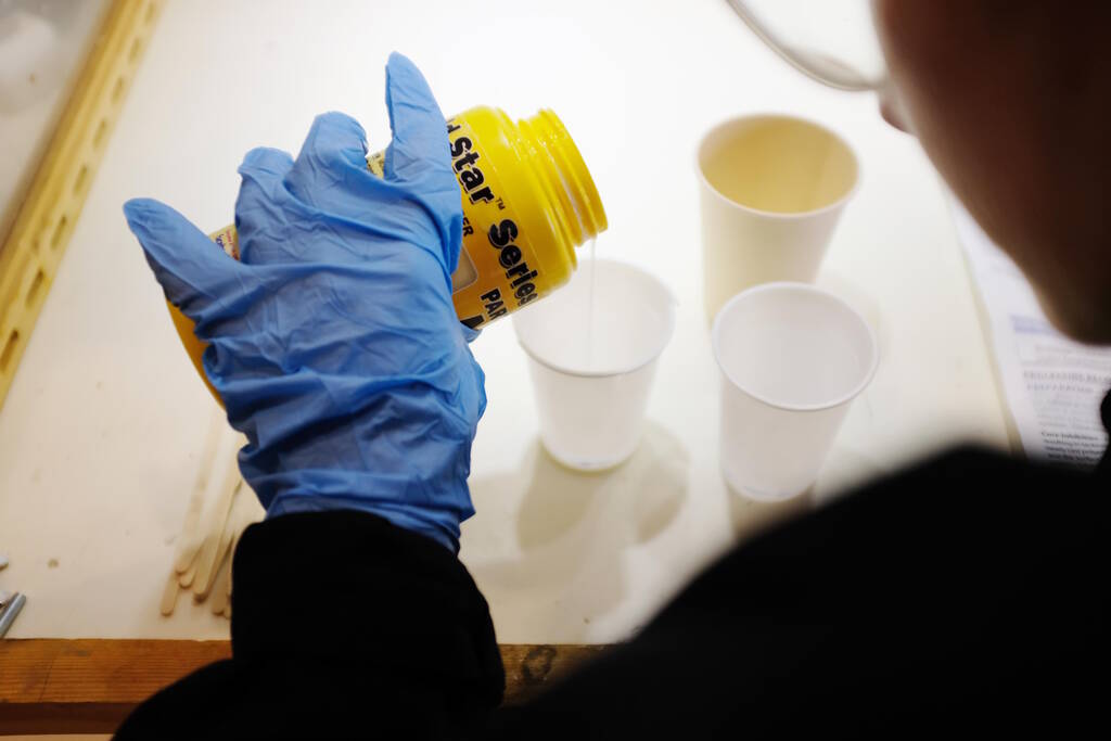
Mixing Mold Star 30
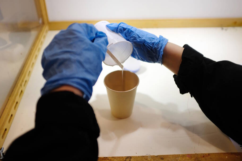
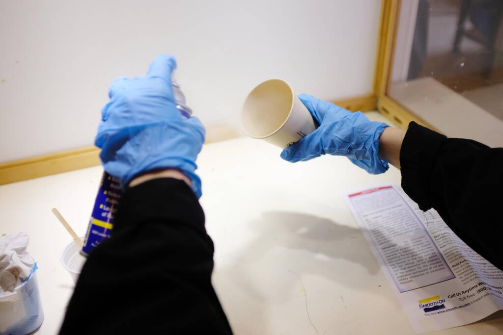
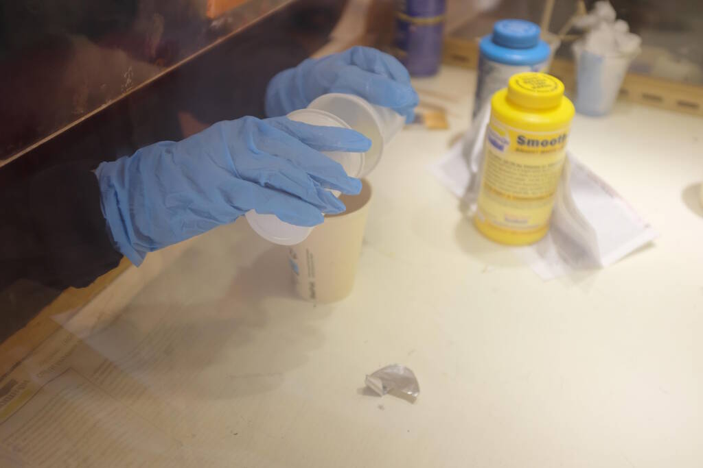
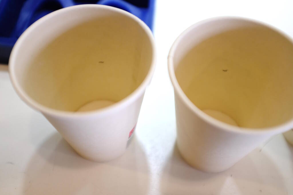
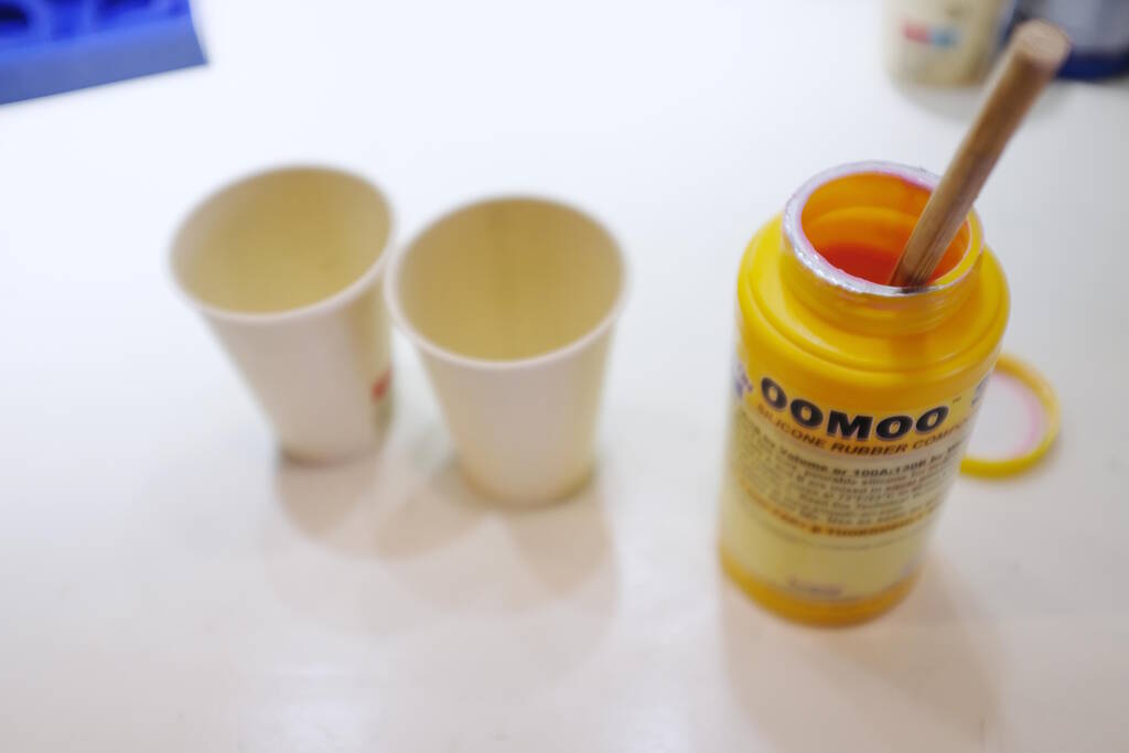
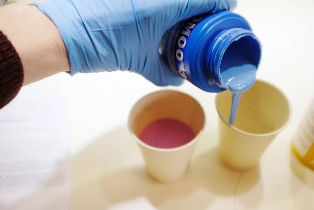
We could measure this by volume but with the cardboard cups that we had, it was difficult to figure out how to make sure we had a ratio of 1:1, so we used plastic cups which allowed us to mark the quantity on the outside. Pouring component A:
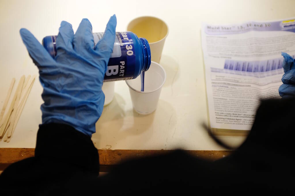
And B:
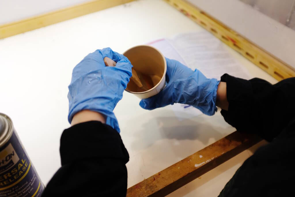
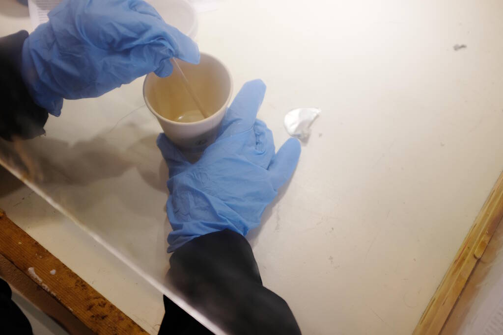
Mixing, trying to get everything out:
Stirring:
Then we noticed "Stir well before using" which we didn't do...
We placed this in the vacuum chamber and were surprised about how many bubbles came out:
Mixing Ecoflex 30
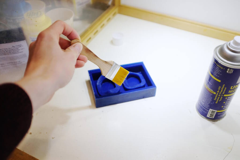
For the Ecoflex, we need to apply mold release:
And use the brush:
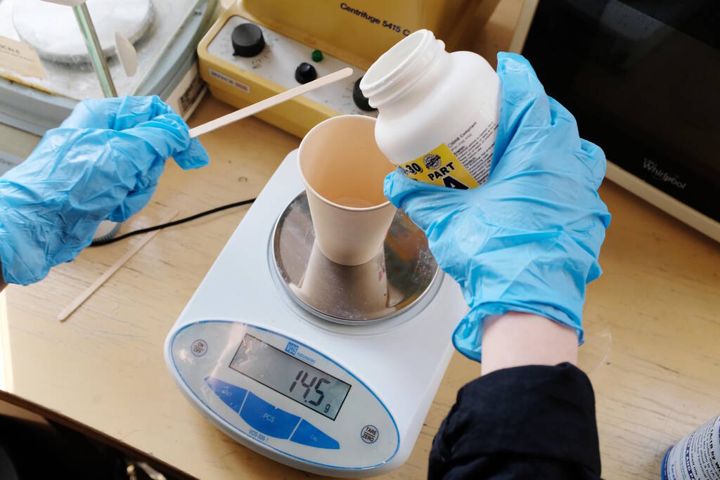
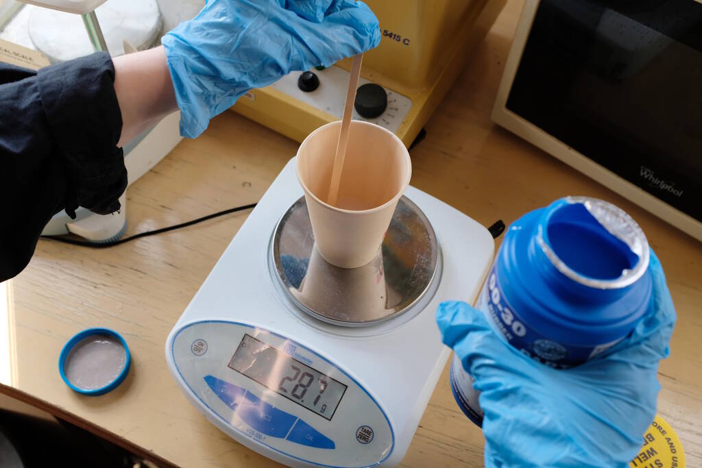
We needed to wait a bit but in the mean time we could figure out the right ratio based on weight:
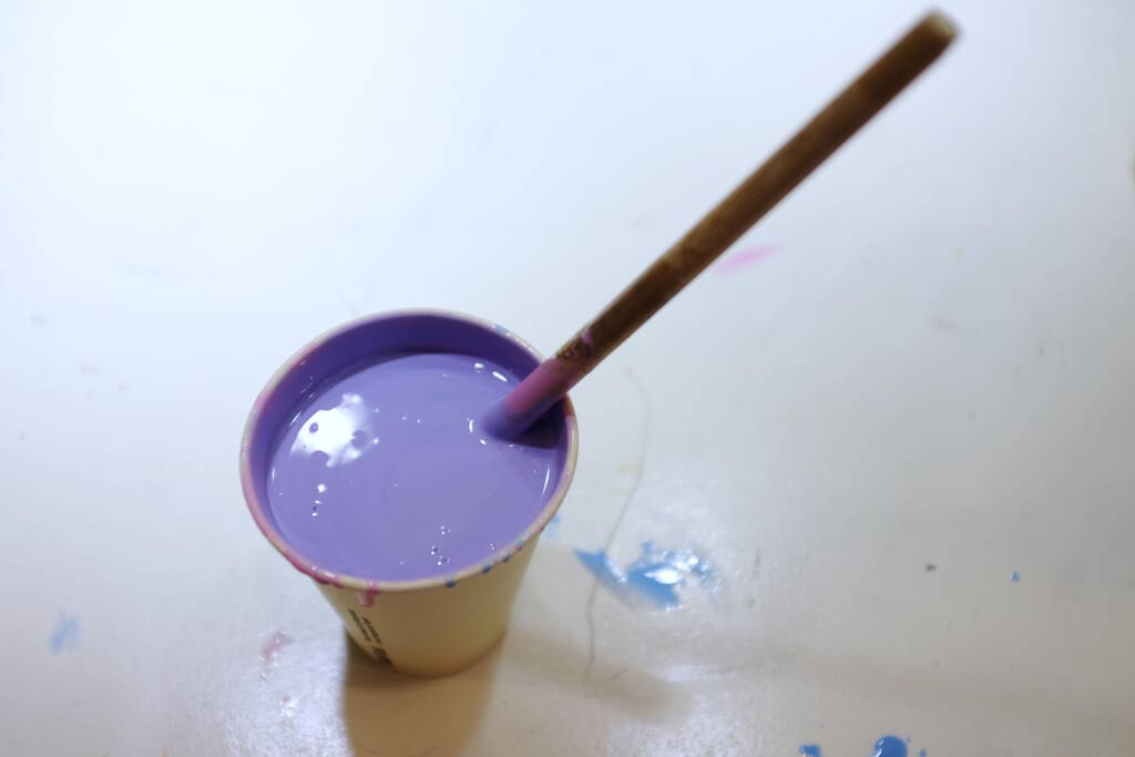
Stirring this time:
Getting the ratio right:
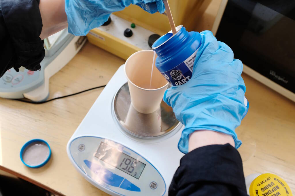
Mixing:
Stirring:
Mixing Smooth Cast 305
Opening up the bottle was not that easy:
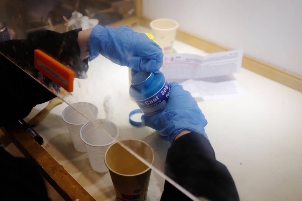
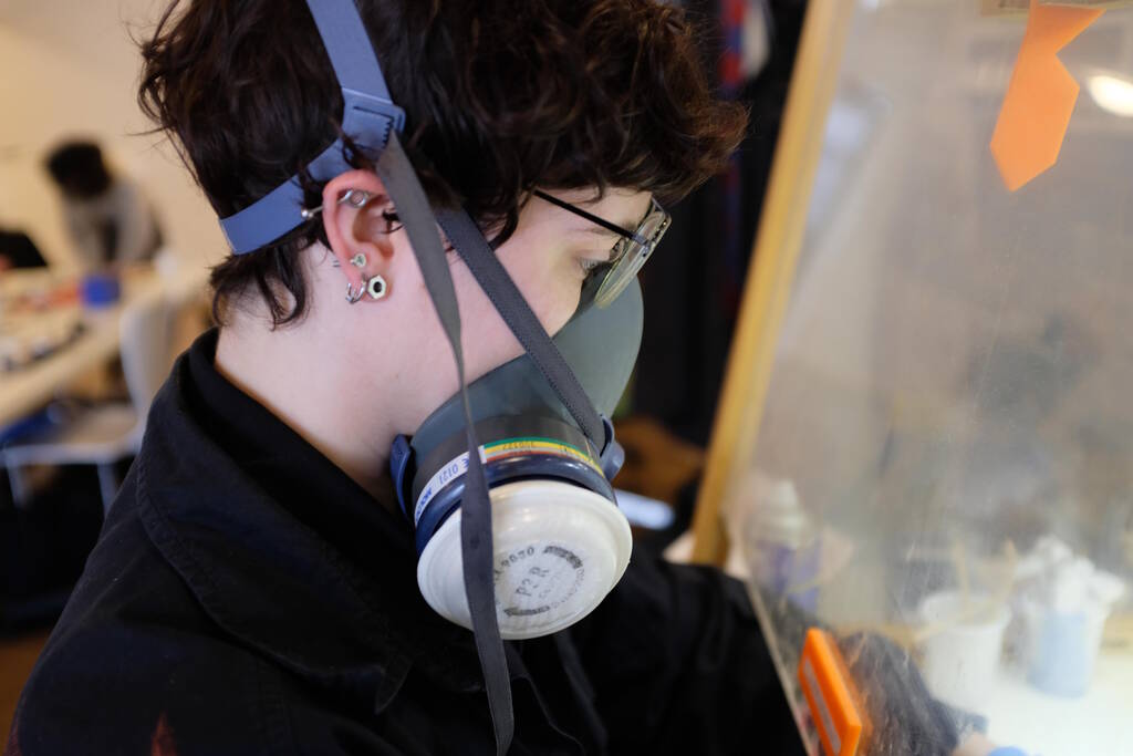
As I explained above, this is a nasty substance, so we wore the face masks:
Pouring component A, the dangerous one:
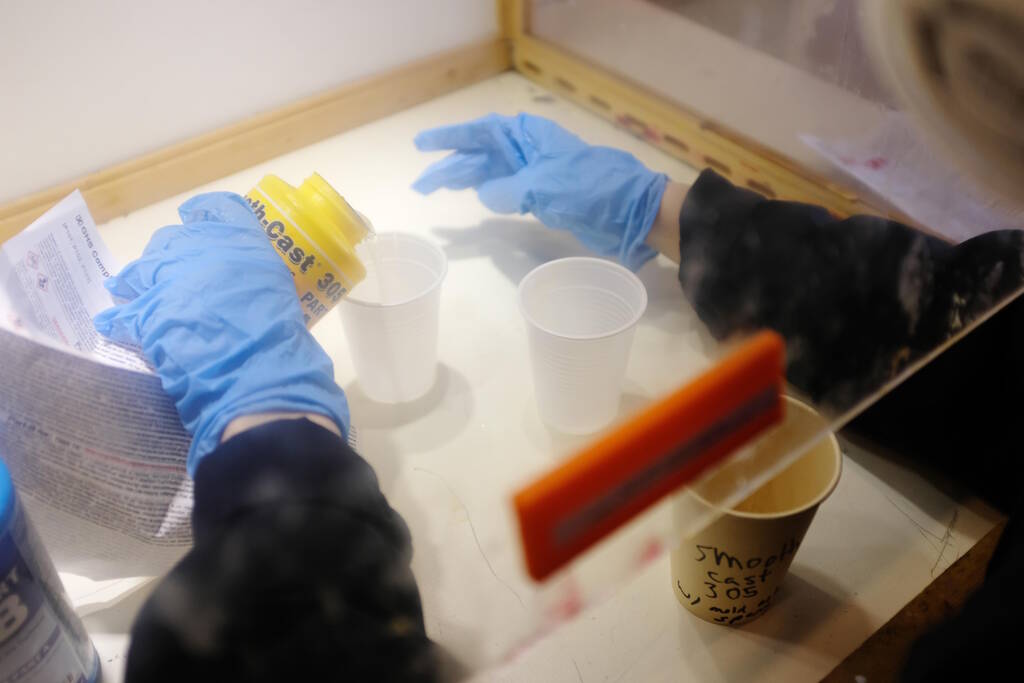
Mixing:
Stirring:
The Result
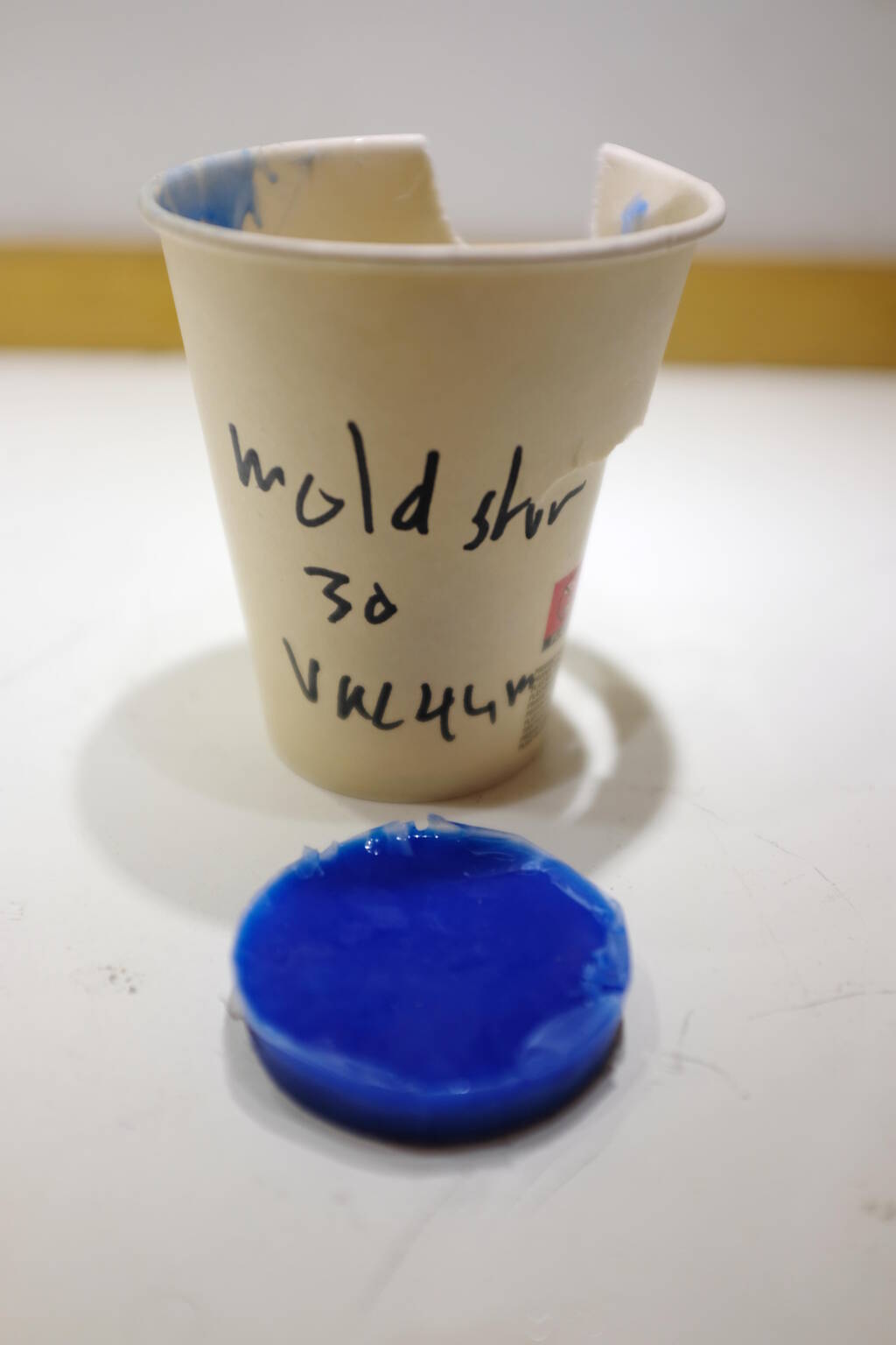
We inspected the result after we let the materials cure:
The Mold Star 30 came out well, despite the fact that we forgot to stir the two components separately:
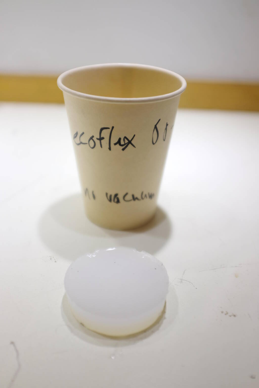
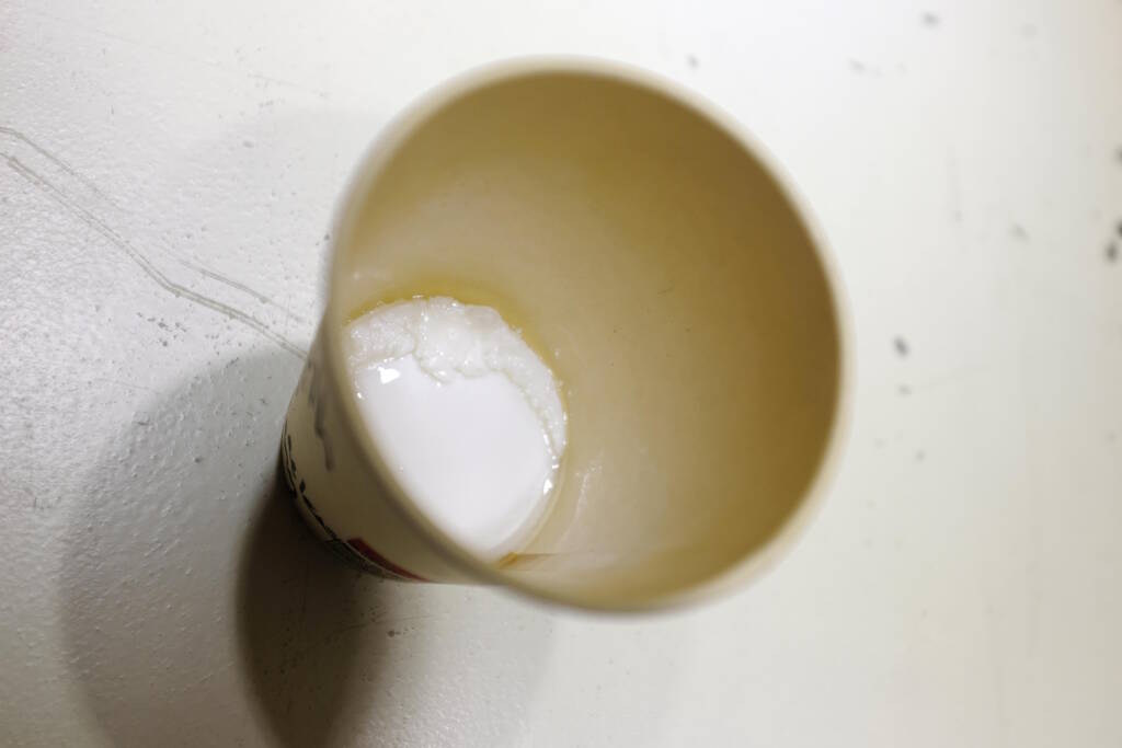
The Ecoflex 30 came out well:
However, the Smooth Cast 305 did not look so well:
Although the Smooth Cast was unopened, it was past its shelf-time (you can see a sticker with 0818:
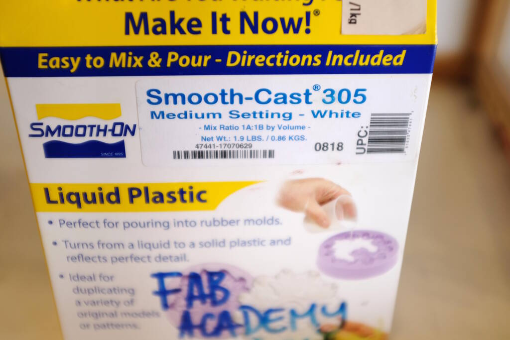
This sticker suggests that the material was from 2018. I later found out that these materials have a shelf life of typically one year, so this was not something that was going to succeed in any way.
Design a Model for Eyes
Given the scan of my face from week 5, I will try to model a rim for the device on which my face fits such that hot water reaches my eyes.
Most likely, the block that we have is not going to be large enough for what I want, so I will decide later what to do, for example, make something for only one eye. For now, I simply design something that will work for the final project.
My idea was to have a rim of about 1 cm wide on which my face rests with a cutout for the nose, such that the water reaches my eyes but I can still breathe. Now that I have a scan of my face from Week 5 - 3D Printing and Scanning , I can design the rim that I have in mind.
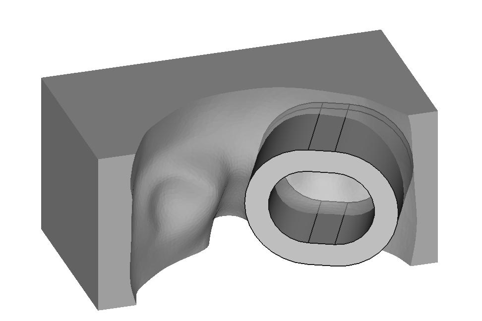
However, after designing this by modeing this both in Blender and FreeCAD, it turned out that the cut out of the nose is actually to low to have water reach the eyes because the water will pour out of it. Additionally, the sides of rim are much higher than I anticipated in weeks 1 and 2. This is a screenshot of the rim that I had in mind (bar the deep cutout for the nose and the high sides):
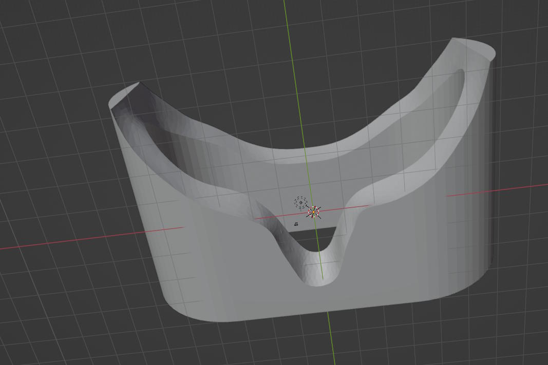
Although I think the cutout for the nose is very useful for breathing, the water can only reach the level of the eyes if my nose actually blocks the water from pouring out. This would mean that I first lay my head onto this rim and then have the water rise to the level that I want. That is much more complicated than I anticipated where the level would reach the cutout for the nose and my eyes would magically be submerged. I could tilt my head, pressing my chin against my chest to make sure that the cutout for the nose is higher, but this seems an uncomfortable position for the 15 minutes that I require my eyes to be heated.
Unfortunately, this model is too high for the block of wax that I have (about 3 cm high), so I cannot really test this. I have to find a different way to make a model given the design that I have.
The process to make this is as follows: The general principle is that I model mesh in Blender and BREPs in FreeCAD. I position the model in Blender so that if I import it into FreeCAD, I can immediately start modeling without rotating. This allows me to reimport the result from FreeCAD straight into Blender. In FreeCAD, I model the rim that I export as STL and import into Blender. Then in Blender I perform a boolean intersection to get the resulting rim.
I then experimented with one eye, but the height difference is still high. Finally, a suggestion from Saco is to rotate the cups for one eye to minimize the height difference:
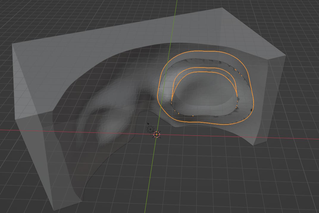
In FreeCAD I designed the following:
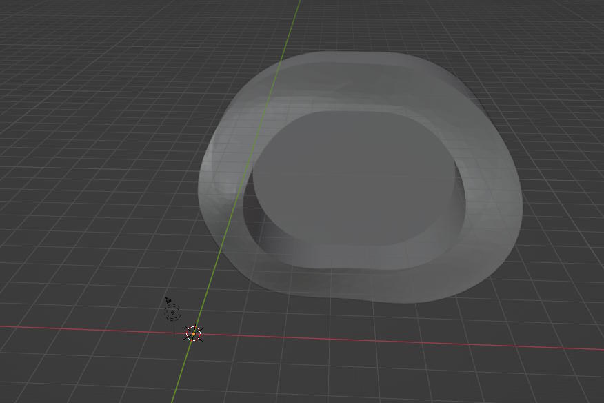
In Blender I take an intersection:
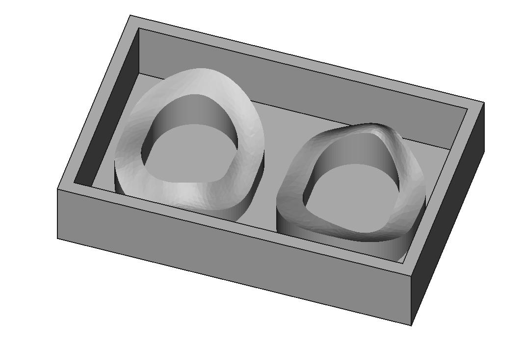
The resulting box is then:
Designing the Box
Designing the box for the positive model was fairly straightforward, but I made a crucial mistake by not "working from the stock" as Neil mentioned. This mistake will become apparent later.
What I should have done is measure the block of wax precisely and model that in 3D. Instead, what I did was roughly measure the box to make sure the model fits. Since I was only interested in the inner dimensions of the box shape, I just modeled a rim that would fit the block of wax.
What I ended up with is the following design:
Setting up the CNC Mill
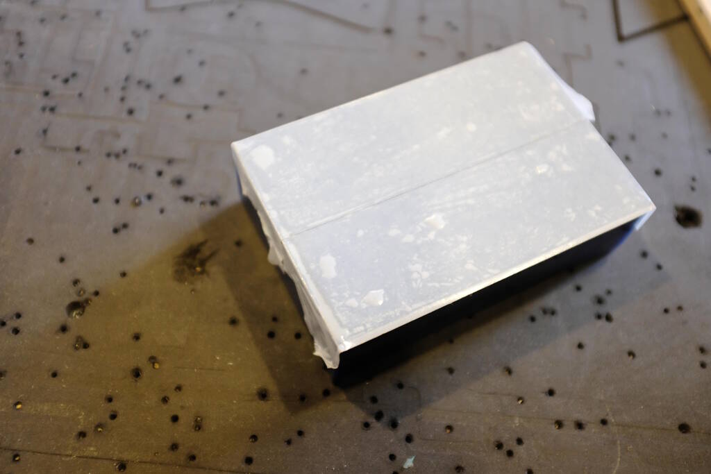
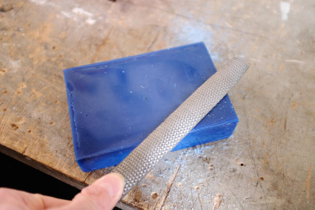
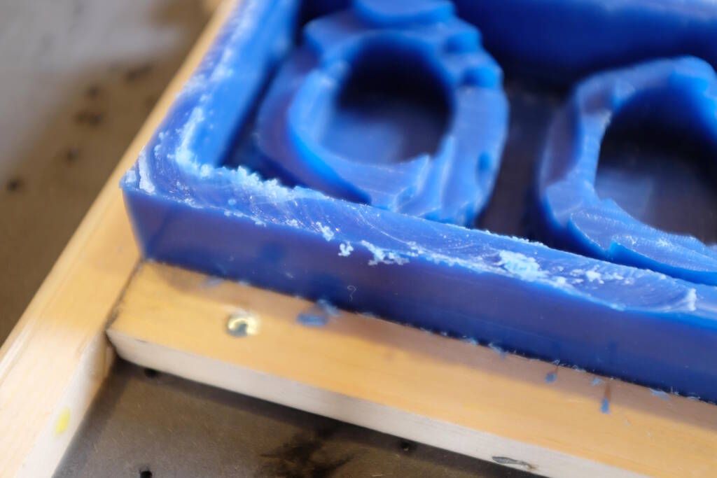
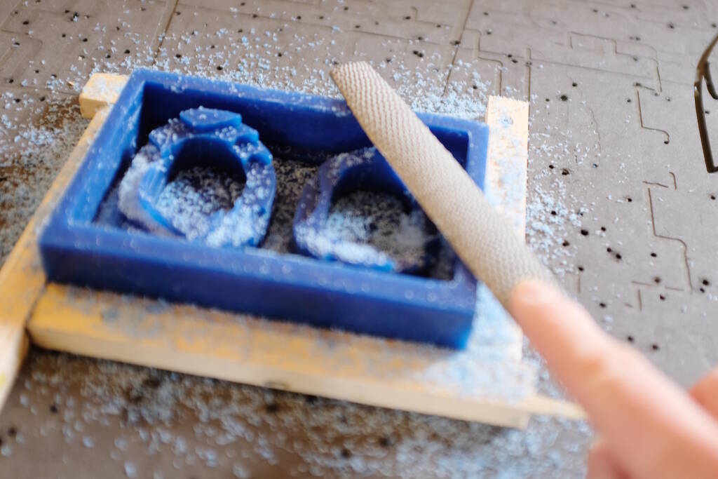
It turned out that my block was not flat on the bottom side:
I used a file to flatten it.
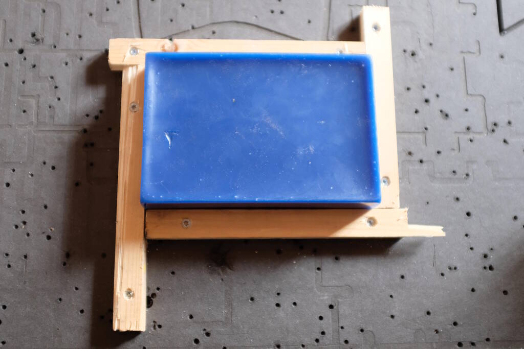
I used double-sided tape and the star form wooden beams to fixate the block:
I also made sure the spindle speed was 9000 RMP:
Setting up VCarve
I found setting up VCarve fairly complicated the day before with Michelle and Saco's explanation, so I kept track carefully of what I was doing. I measured the block of wax precisely, which turned out to be 96 by 144 mm. The height varied in the corners and I measured a thickness of 35.6, 33.6, 33.4, and 35.0, so I used the minimum value.
After consulting with Saco, I checked whether the mill bit could go deep enough. We concluded that it was going to be tight, because the mill bit was 50 mm, and it should have at least 18 mm inside the collet, so there would be 32 mm left.
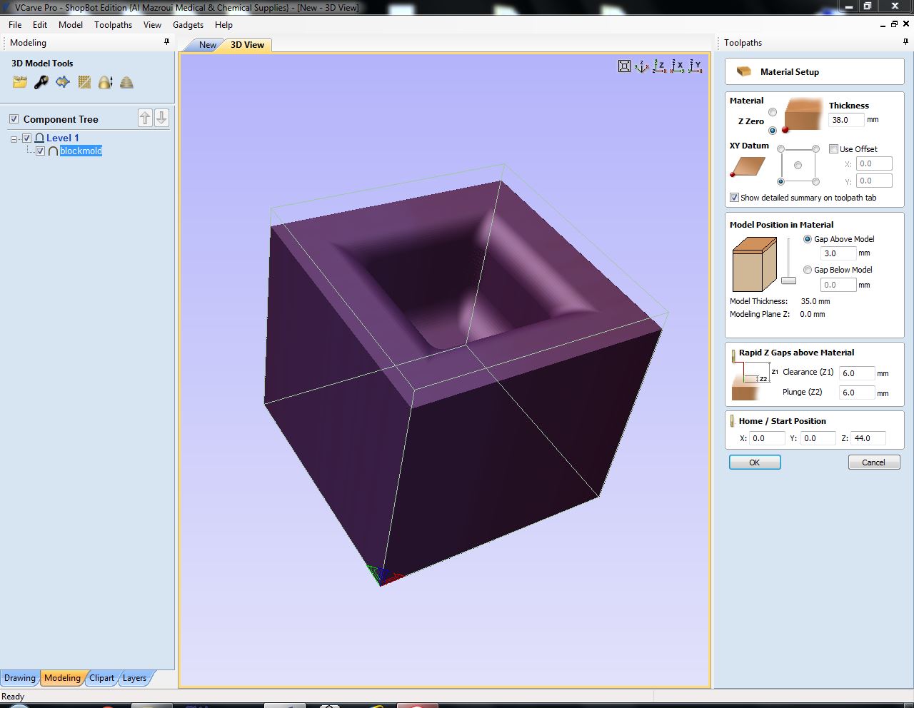
Setting up the Material and Model
I decided to choose the stock size a bit smaller because this allowed me not to be too precise on setting the X and Y coordinates. However, this turned out to be not such a good choice because then the software doesn't know about an outer edge that still exists. This will become a problem in the next section. I chose 141 mm for the X axis (instead of the 144 mm that I measured) and 91 mm for the Y axis (instead of 96 mm). For the thickness I chose 33.4. I chose modeling resolution high and a blue color because my block of wax was blue.
What is tricky at the CNC is that the long side is the X axis and my model had the long side at the X axis as well. However, the computer is at the Y axis and from the Y axis you have the best access to the sacrificial layer. So, it is very tempting to place the model such as if the side that you have access from is the X-axis.
I made this mistake as well and in the following picture you can see that I placed the block of wax such as if the horizontal axes is the X-axis, but in fact it is the Y-axis.
Luckily Saco spotted this mistake. So, I started all over with a new file using a 141 mm for the Y axis instead 91 for the X axis using an orientation of -90 degrees to make the model fit.
I designed the bottom of the box to be 2.5 mm thick but Saco was of the opinion that this was a bit thin, so in "Material Setup" we adjusted the placement of the model in the material setting the "Gap Below Model" to 1.5 mm which resulted in a "Gap Above Model" of 2.9 mm automatically. This would make the bottom 4 mm thick.
Defining the Rough Toolpath
I used a 4 mm end mill with pass depth 4 mm and a stepover of 80% using 9000 RPM for the spindle speed, a feed rate of 90 mm/s, and a plunge rate of 30 mm/s. I chose "Model Boundary" for the "Machining Limit Boundary" with a "Boundary Offset" of 0.0 mm. I think, however, that I should have chosen "Material Boundary" for this toolpath including using the correct measurements of the block of wax. The "Machining Allowance" was 0.5 mm and I chose as strategy "Z-level" "Raster Y" which ensures that not the whole Y-axis has to be moved, but just the head on the Y-axis.
Defining the Finish Toolpath
I used the same 4 mm end mill with a stepover of 13% using 9000 RPM for the spindle speed, and a feed rate of 60 mm/s. The "Machining Limit Boundary" was set to "Model Boundary" again with a boundary offset of 1.5 mm. Now that I'm reporting this, I don't understand why this value was 1.5 mm and not 0 mm. I will ask Saco about it.
Since I don't want steps in my model (I want it to be smooth to my skin), I used two finishing passes, one with "Area Machining Strategy" set to "Raster" with a "Raster Angle" of 45 degrees and one with a "Raster Angle" of 135 degrees. I choose to do both diagonally because then for both passes, the Y and X axis have to move. If I would have chosen 0 and 90 degrees, then for one the X axis would have all the movement, and for the other one the Y axis. It seemed more "regular" to use both axis movements on both passes.
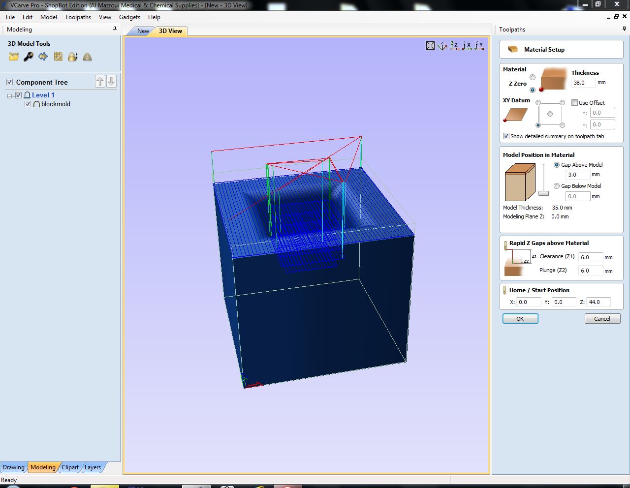
Simulating the Toolpaths
Although I simulated all three toolpaths, they looked fine to me. I didn't catch that for the rough toolpath, the outer edges of the block were not cut away. Even if I had spotted that, I don't think I would have guessed that this would have ramifications later on...
Milling the Model
Initially, the cutting went fine:
However, as I said above, I didn't pay attention to what happened to the top layer in the rough cut. It turned out that the rough cut did not remove the outer edges with three different (likely) causes:
- Because of the offset parameter the milling stayed away from parts that I anticipated to be cut away.
- Because of not choosing "Material Boundary", the rough cut did not cut into the outer edges.
- I used too small a stock size resulting in parts of the wax block of which the software was not aware.
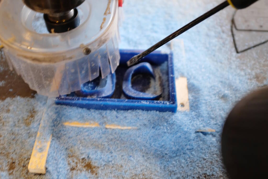
Because of this, the collet was bumping against the outer rim of the box.
Saco was there as well and we decided to stop the rough cut and file away the high parts.
Unfortunately, it was getting late and I had to leave for home. Luckily the others could simply use a different part of the machine and I would get back to it on Monday. I was smart in recording the absolute coordinates that I made my job zero coordinates (X: 143.412, Y: 335.394).
On Monday, I noticed that Michelle had used a 3 mm milling bit so I changed back to the 4 mm one. Since the rough cut was almost done, I continued with the two finish cut toolpaths and the following video shows that it is close, but the collet doesn't hit the rim anymore.
Inbetween the two fine toolpaths I paused the job and removed the chips just to make sure that the tool can move freely.
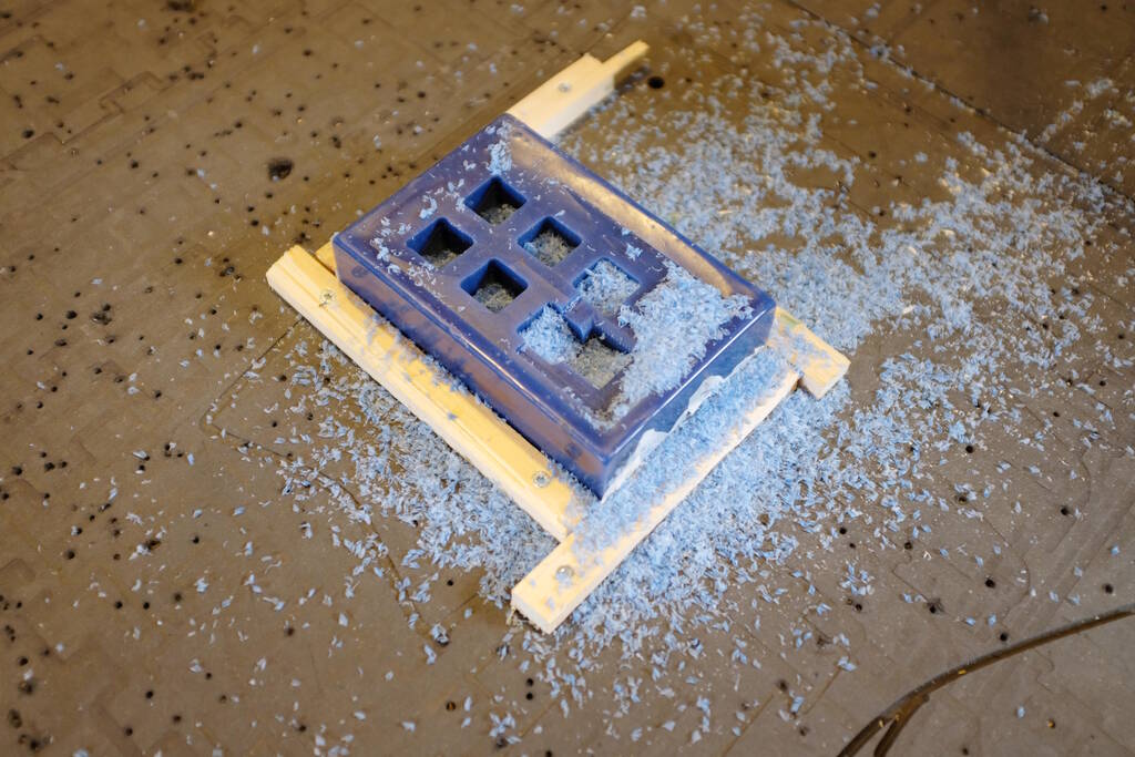
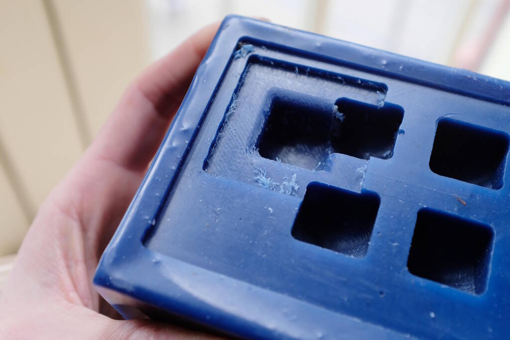
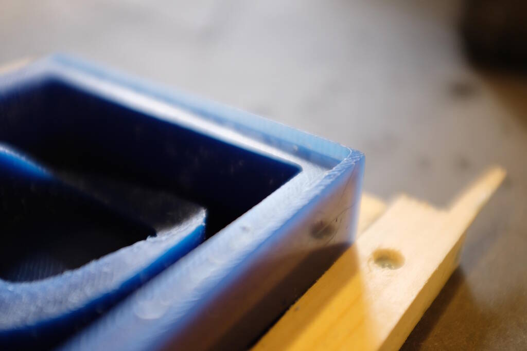
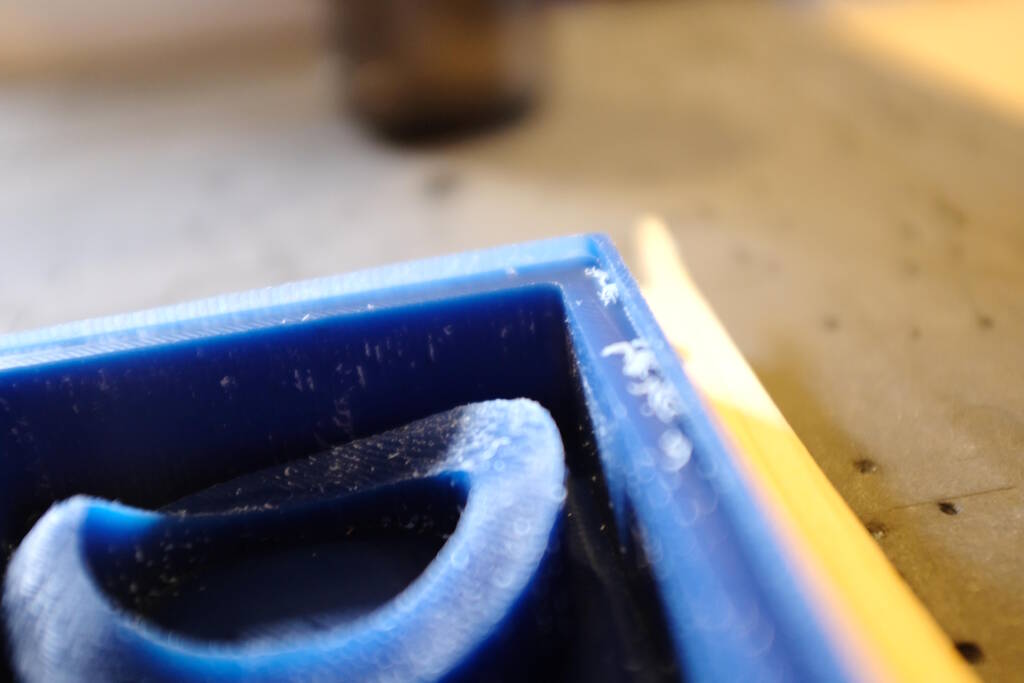
The result is the following:
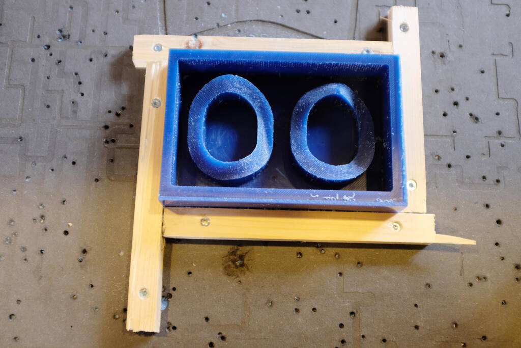
You can see the rims that were left because I didn't set the stock size to the true dimensions of the block:
Casting the Negative Mold
As a rule of thumb, Henk and Saco mentioned that if you want a stiff end product, you cast in a flexible material and vice versa. So, based on this, my plan was to cast with Smooth Cast 305 for the negative mold which will result in a stiff negative mold. My idea was then to use Ecoflex to create a material that is soft and it safe to touch my skin.
However, Henk asked me how I would get the hard negative mold out of the wax model. This will indeed be difficult, so this rule of thumb is not completely true I think. So, now I have to understand how in which softer material I can cast eco flex.
Reading the Data Sheets
The data sheets are called Technical Bulletins and I started with Ecoflex to understand if I could cast it in OOMOO.
Ecoflex
A critical point in the data sheet of Ecoflex is that tin-cure silicone (which OOMOO is) may cause cure inhibition. They recommend to do a test run. Since this whole exercise is a test run, I'm not going to do that and I wouldn't have time.
To prevent this inhibition, it is recommended to apply one or more coatings of clear acrylic lacquer to the OOMOO negative mold in this case. Henk looked into this and stated that I can use the mold release as sealer. Let's try this and see how it goes.
OOMOO
Reading the data sheet for OOMOO, it catches my eye that they recommend to level off the rubber at least 1.3 cm over the highest point of the model. This may be a serious problem in my model. Unfortunately, I'm very limited in terms of depth of the milling bit. So, this is another factor that can influence the result. Let's wait and see what comes out of it. The dimensions of my model as tight anyway, so I have to be very careful demolding the OOMOO.
The data sheet also makes it clear that no release agent is necessary in wax. Perhaps I do this afterall because of the thin bottom of my negative mold.
Measuring the Quantities
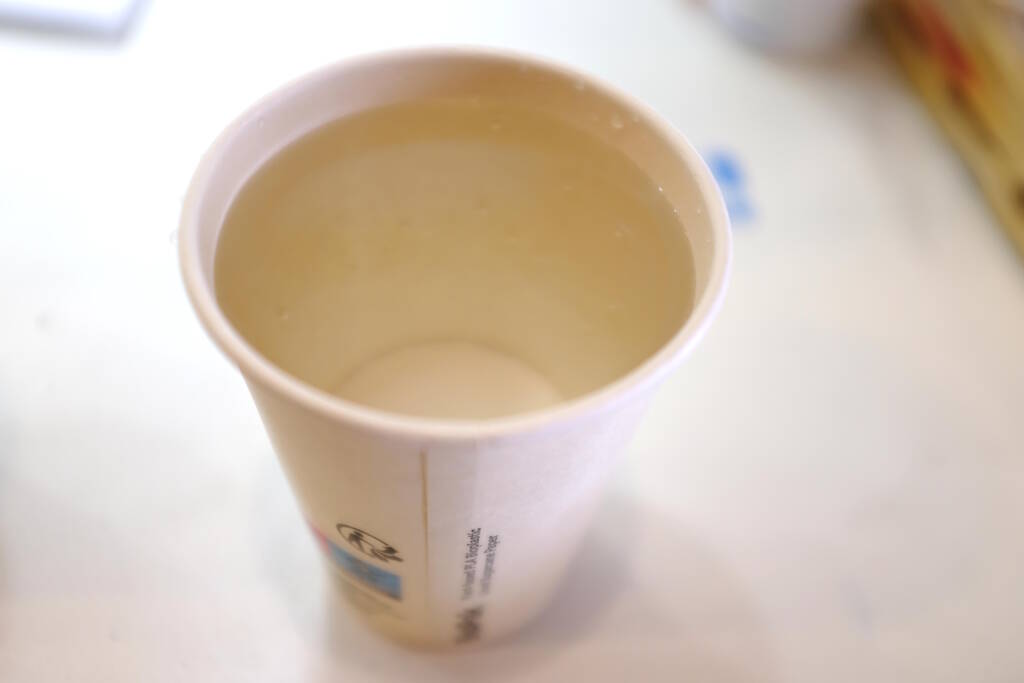
I filled the wax model with water and tried whether it would fit in a cup, which it does:
I poured the water in two other cups to figure out to what level I would need to pour:
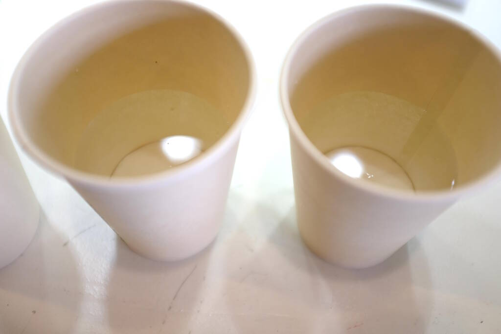
I marked it:
Stirring
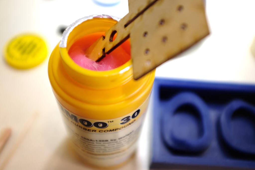
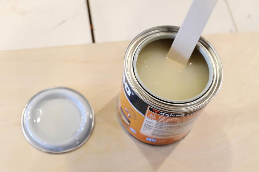
Henk bought fresh OOMOO but immediately after I started stirring, it seemed not right. I asked Henk and he told me that I just had to stir well:

The tiny wooden sticks were not enough, so I was looking for other pieces of wood, from our failed ornithopter:
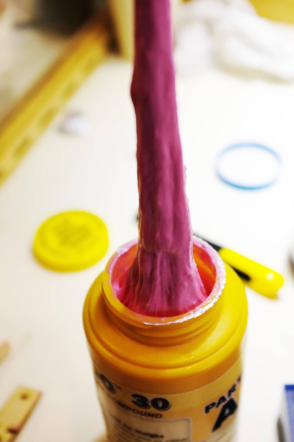
After 20 minutes of stirring with ever more stronger pieces of wood, the component was unpourable. I could simply keep it upside down and nothing would come out. Since I didn't have experience I didn't know what to expect. Henk showed me a video where they could actually pour it and that was not what I had.
I checked the shelf life and the Smooth-On Shelf Life page stated that I should look at the production time stamp from the lot number, where the first two digits is the year and the second two digits is the month. The lot number was Lot# 2101462 for component A and Lot #2101601 for component B. Most of the materials have a shelf life of 12 months except for OOMOO that has a shelf life of 9 months, so this material expired in October 2021, which means that it is one year and a half overdue.
Second Attempt
It is now Wednesday 26 April and Henk got us new OOMOO that was manufactured in September 2022, so it will last us another 2 months. I am continuing the process now.
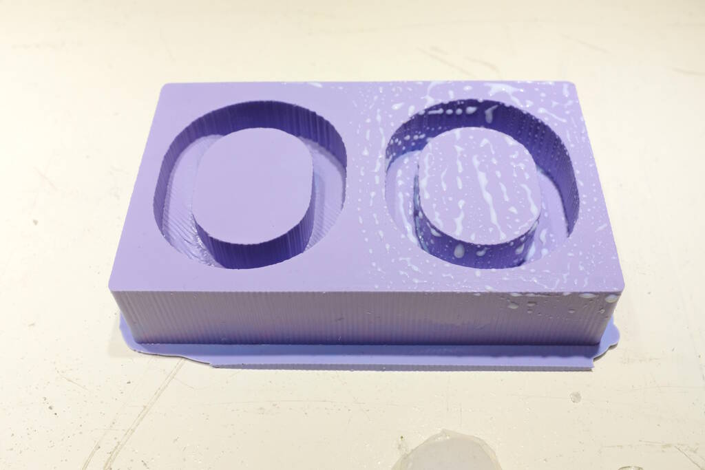
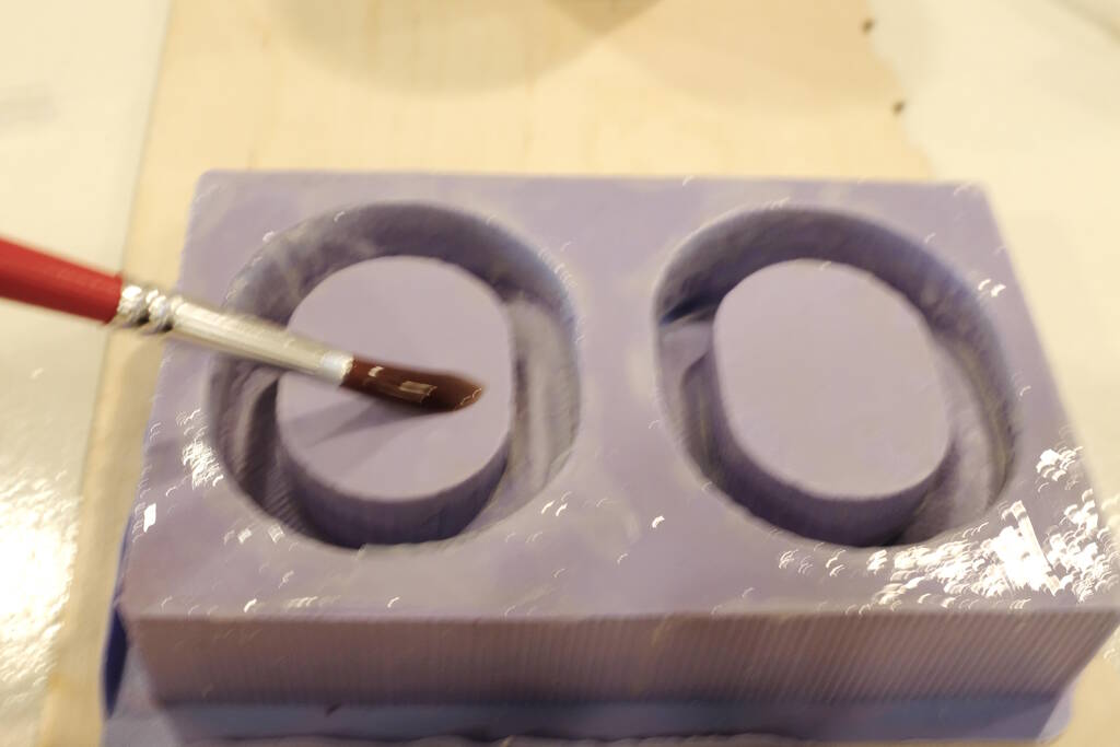
Before stirring, I first sprayed mold release on the wax model. This is not strictly necessary but since the bottom of my negative mold will be very thin, it seems to be a good idea. I sprayed it on:
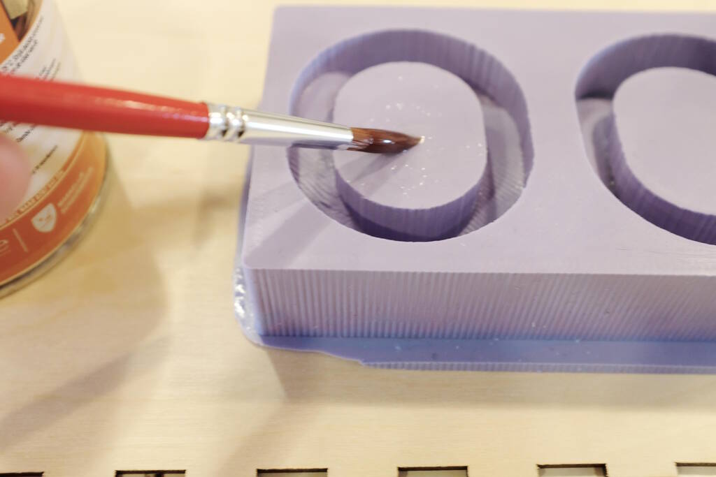
Brushed on all the surfaces:
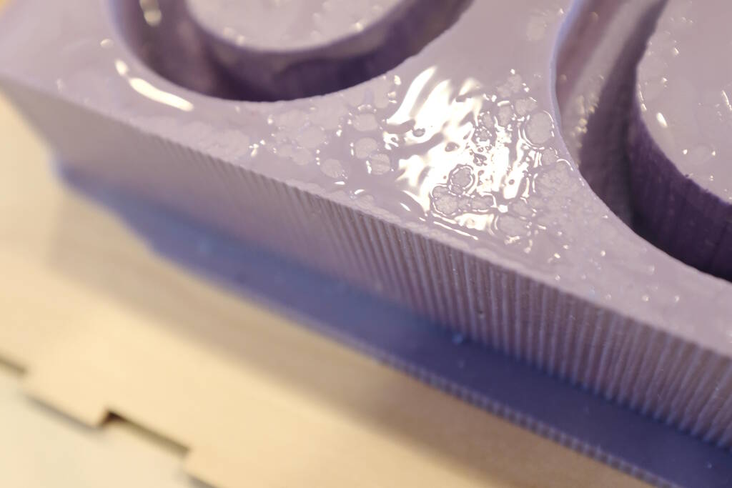
And sprayed on another layer. You have to let it sit for at least 5 minutes.
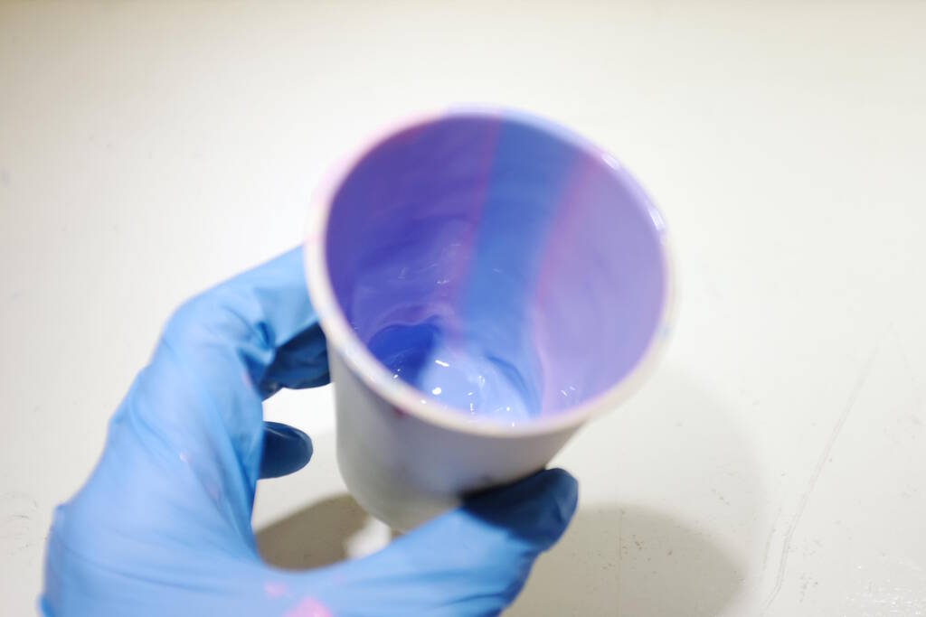
I stirred each component, which was a completely different experience than with the overdue one:
I poured it in two cups:
Started mixing:

Until it was even:
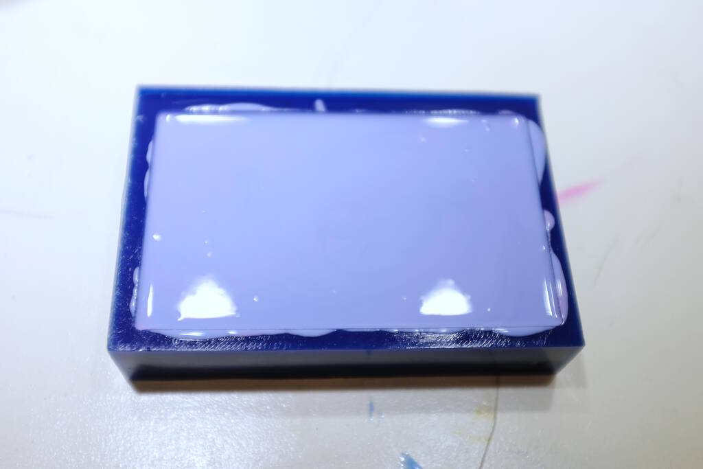
I poured it in but it turned out that in the end it didn't mix well at the bottom:
I decided to stir in the mold itself to make it mix better and this worked well. I already feared that I didn't have enough because the material is so sticky:
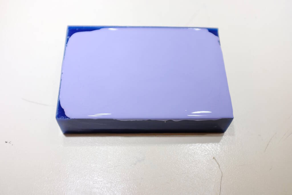
Since the bottom part of my model is so thin, I decided to mix more and pour that in as well with this as end result:
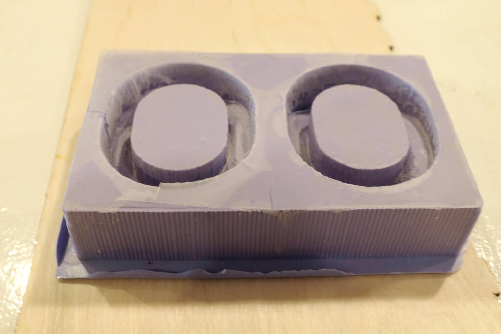
The next day I could remove it:
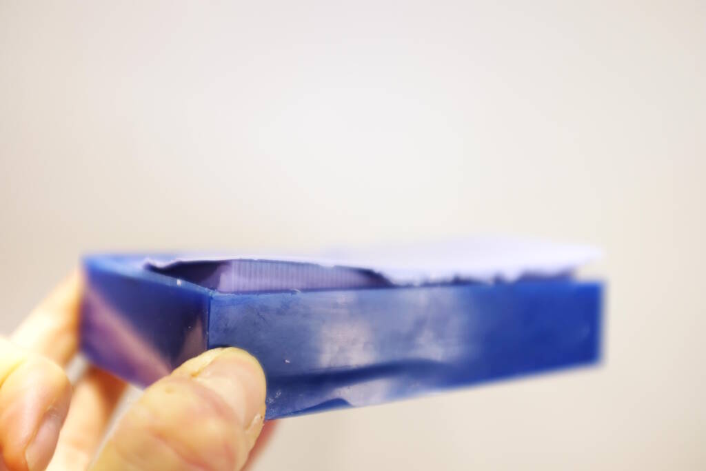
Step by step:
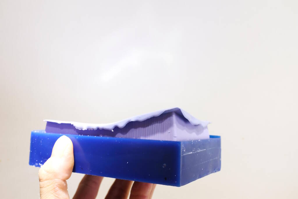
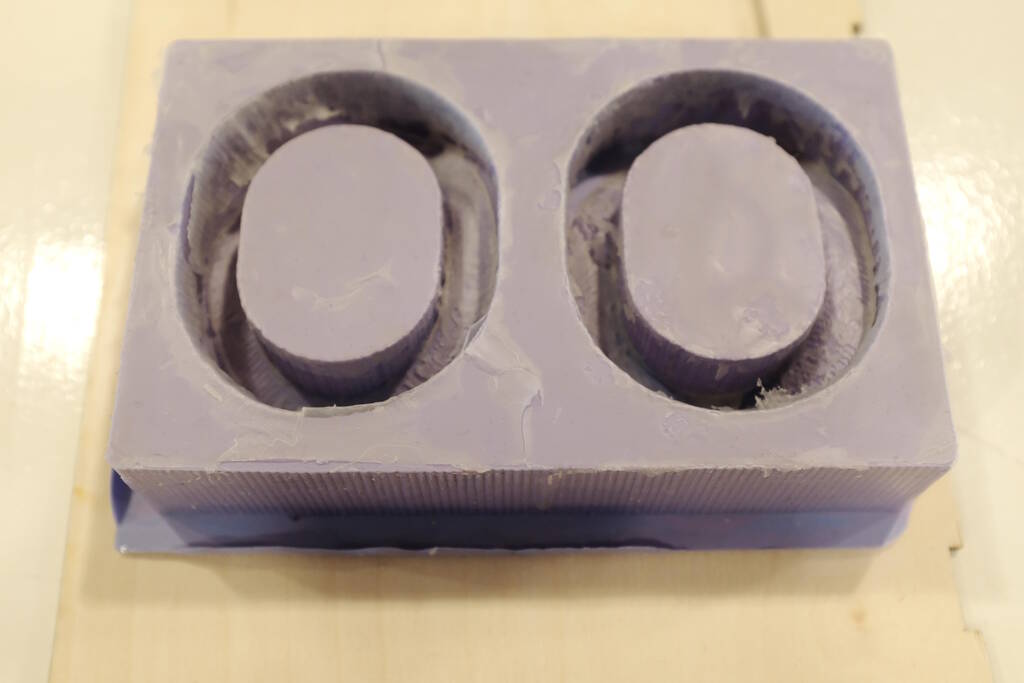
And this is what came out:
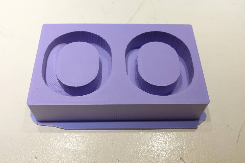
It came out well.
Casting the Object
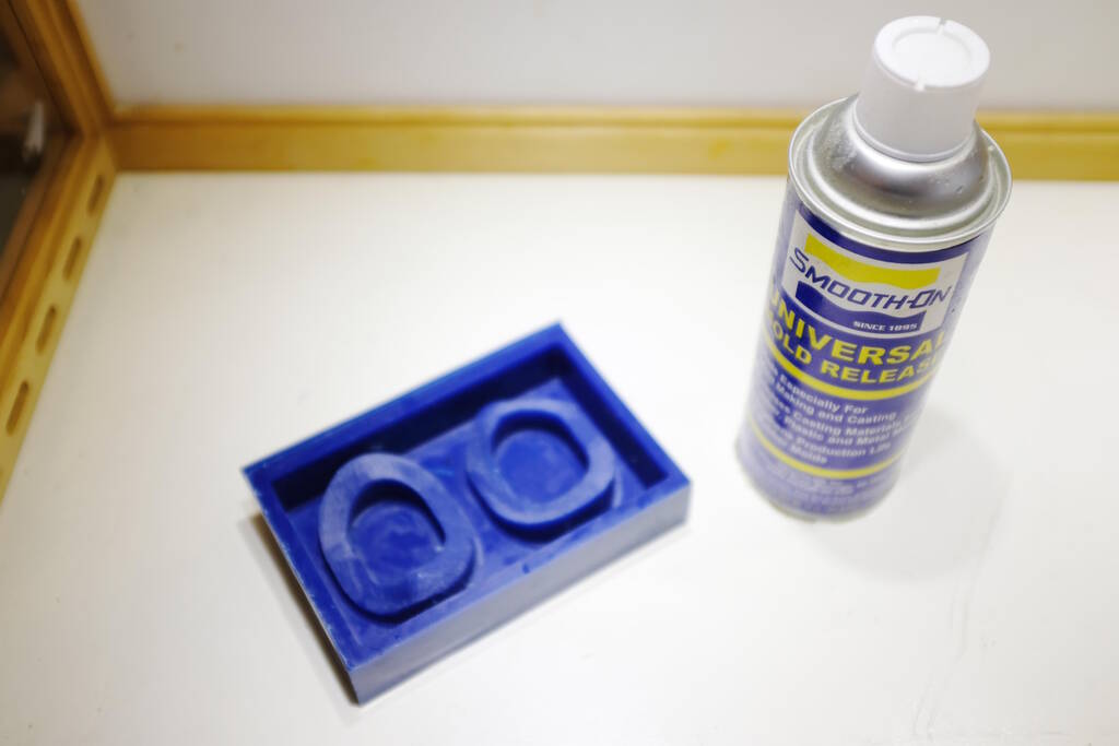
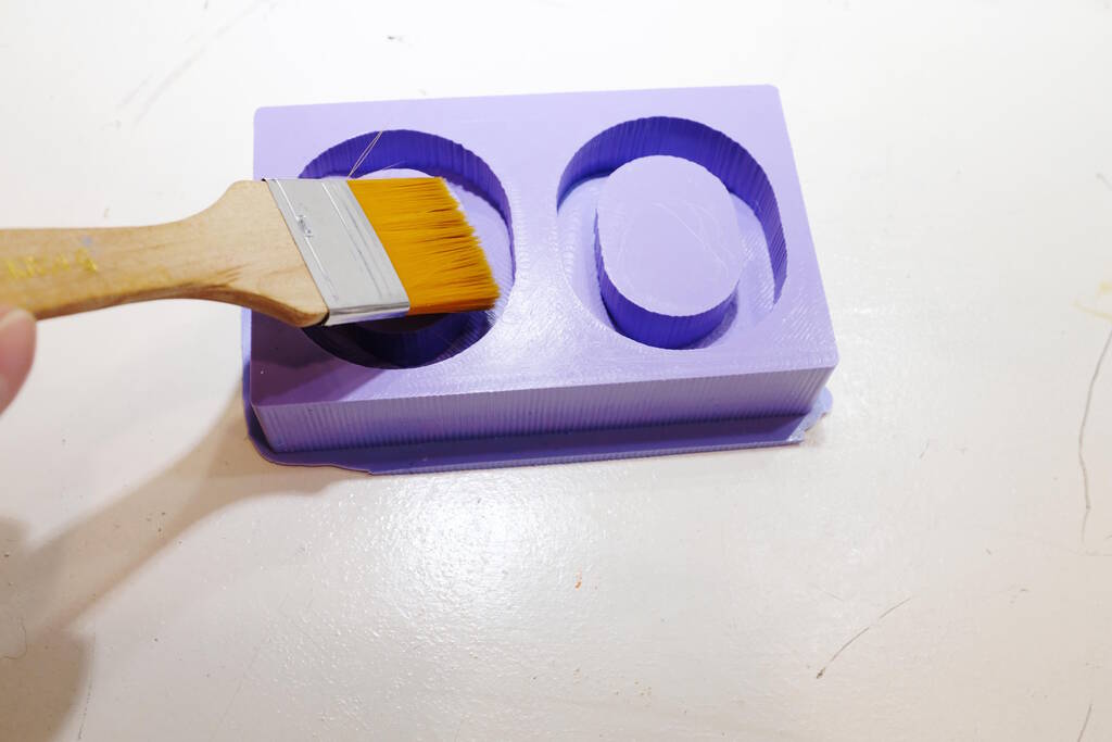
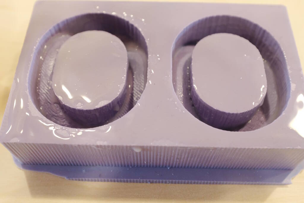
As mentioned before, the data sheet states that we may experience cure inhibition with the combination of a tin-cure silicone mold. They recommend to use clear acrylic lacquer as a sealer but we don't have that. From Samson's experience, we already know that without a sealer the Ecoflex won't cure, so I'm not going to repeat that but apply mold release as a sealer (this was recommended by the store where Henk bought the materials).
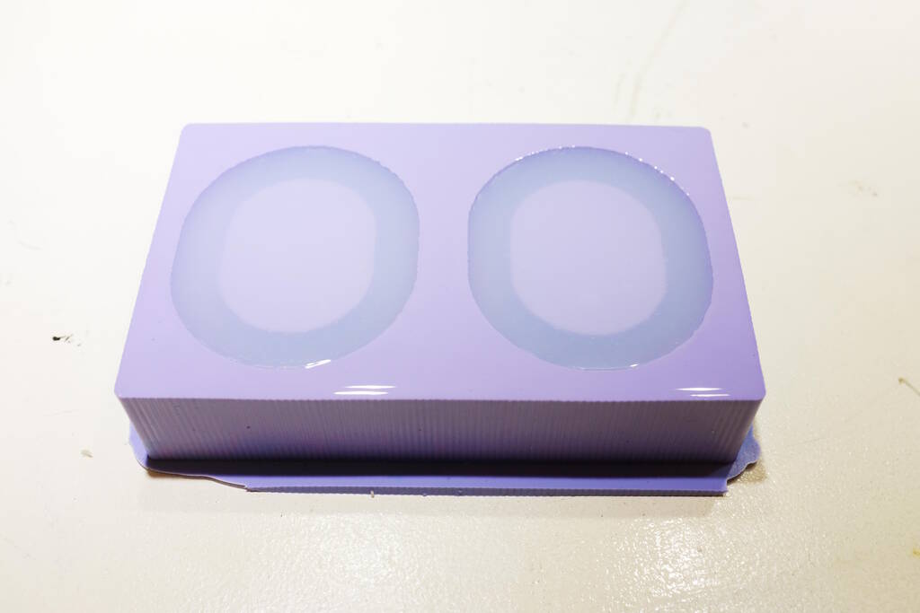
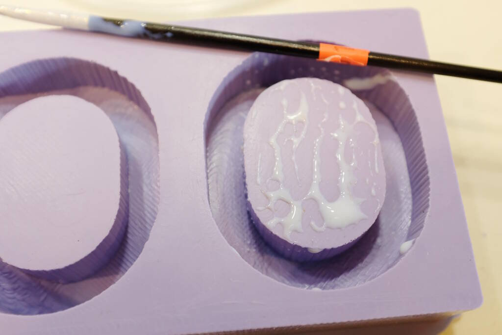
So, I carefully applied mold release:
I poured in the Ecoflex:
Then I tried to get it out:
But it turned out that the curing process had indeed been inhibited:
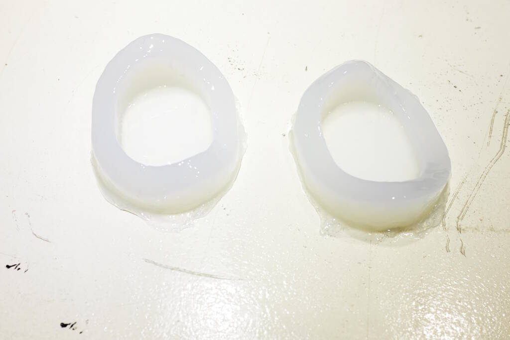
Sticking to my fingers:
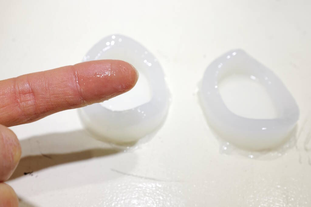
So, this clearly didn't work. I will try to find acrylic lacquer and try again.
Sealer between Oomoo and Ecoflex
I tried various sealers. This is acrylic medium:
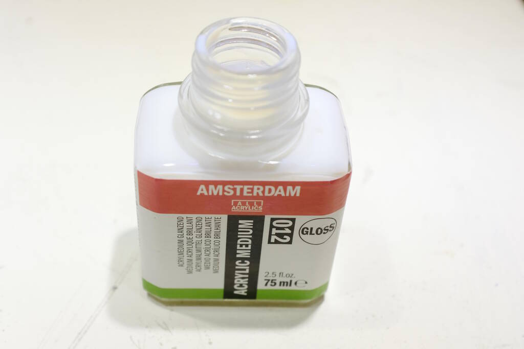
Unfortunately, it doesn't stick at all:
Then I got acrylic clear lacquer as they suggested in the technical bulletin of Ecoflex:
Unfortunately, while applying it to the Oomoo, it was quite clear that this didn't stick either:
In the end, I tried to get it applied to the best of my abilities, but it wasn't good:
Adding more layers before the paint dried completely improved the situation a bit, but essentially didn't work either. This was 25 minutes later.
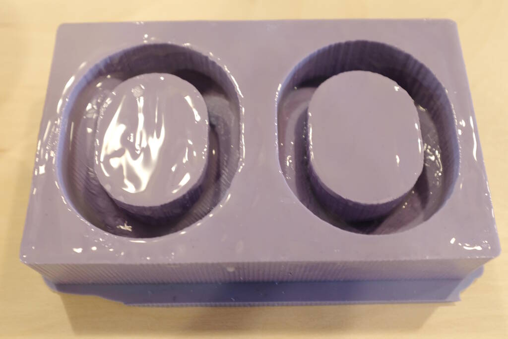
This was what came out, not good:
I added another layer on dry paint:
But the result is still not good:
At this point I'm running out of ideas and I want to close off this week. I will investigate solutions for all this at a later stage.
Tasks
Fab Academy
- Review the safety data sheets for your molding and casting materials.
- Make and compare test casts with each of them.
- Design a mold around the stock and tooling that you'll be using.
- Mill the mold with a rough cut and at least a three-axis finish cut.
- Use it to cast parts.
- Demonstrate workflows used in mold design, construction and casting.
Personal
- Redo the casting with acrylic lacquer as sealer.
- Investigate alternative ways to seal Oomoo
Files
Table of Contents
- Lecture Molding and Casting
- Milling a Block of Wax
- Introduction to the Materials and Equipment
- Review Safety Data Sheets
- Testing the Materials in our Lab
- Design a Model for Eyes
- Designing the Box
- Setting up the CNC Mill
- Setting up VCarve
- Milling the Model
- Casting the Negative Mold
- Casting the Object
- Sealer between Oomoo and Ecoflex
- Tasks
- Files