Lecture Input Devices
Erwin gave a very interesting lecture on input devices again and in this section I will highlight the main takeaways for me.
Analog Devices
Analog devices are (obviously) much harder to read than digital devices and microcontrollers can only measure voltage. Often, microcontrollers have only one ADC and a selector that determines which pins are measured by the ADC. If multiple pins are selected to be measured, then this is likely to happen round-robin, potentially decreasing the sample frequency.
An ADC consists of a resistor network with comparators where the number of resistor/comparator combination determines the resolution in number of bits . Often microcontrollers have a setting to measure in the 1.1 V (1V1) to compensate for low resolution. They can typically also measure using their reference voltage.
Input devices often have a so-called Wheatstone bridge , which is a small circuit with resistors. By chosing resistor values properly in this circuit you can calibrate the output voltage of the sensor to be in a voltage range that is good for measuring on for example a microcontroller.
Digital Devices
Digital devices can be measured with GPIO pins. Typically the range between 0 and 1/3 of VCC is considered low, whereas 2/3 of VCC to VCC is considered high. Everything inbetween is considered undefined. Pull-up and pull-down resistors can be used to force a particular signal. Arduino-type microcontrollers often have an internal pull-up resistor on the pins, but the RP2040 has both internal pull-up and pull-down resistors.
Protocols
I was unfamiliar the 1wire interface. It can use three wires, VCC, ground, and one data wire. Sometimes data is even combined with VCC.
SPI and I2C are protocols that I have heard about now but Erwin refers to serial communication as "just serial". I now understand why serial is called "just serial" because the more advanced protocols typically have a clock that helps to determine when and how bits are sent over the wires. However, with serial communication, a device "just" sends the bits at a specific rate, the baudrate and the receiving device should simply listen for a signal at the same baudrate. So, that's why you get garbage when you listen at the wrong baudrate.
Finally, I didn't know that PWM can be considered a protocol as well. I guess (but didn't verify) that servo motors are actually already controlled with PWM as a protocol.
Interesting Devices
Interesting devices we discussed are the PCA9555 I/O expander and the VL51L0X time-of-flight sensor for measuring distance using a laser . Both devices happen to speak I2C .
Low and High Pass Filters
What was very interesting for me was Erwin's explanation of a high pass and low pass filters. I've seen this in relation to audio amplifiers and I know it works with capacitors but I didn't understand it.
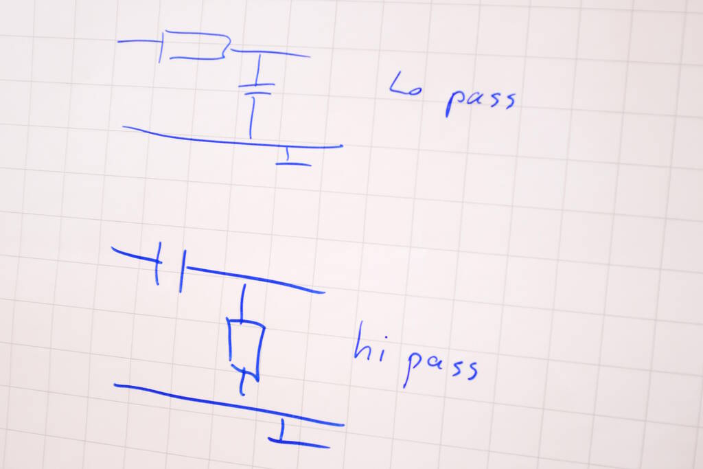
Erwin explained it to me last Thursday, so let's see if I can explain it in my own words: At the top we have a low pass filter . The bottom wire is connected to ground, so the signal comes from the top wire. Suppose the top wire has a high signal. As such it charges the capacitor and if the capacitor is fully charged, it will not deliver any current. Suppose the top wire becomes low, then the capacitor will deliver current for a brief moment in time after which it will be fully discharged and will stop delivering current. If this switching on and off happens at a low frequency, there is a small delay and offset because of the capacitor, but in principle, the output wires will reflect the low frequency of switching the top wire on and off.
Suppose now that the top wire is turned on and off at a high frequency, the capacitor will take over delivery of the current for a brief moment and the output wire will not reflect the high frequency of switching in the input wire. This is true if the capacitor can hold enough charge to compensate for the frequency.
For the high pass filter let's assume that the signal is low. The output signal will be low as well. If we make the input wire high, the capacitor will charge itself and while it is charging, the output remains low. If the capacitor is fully charged, the output remains low. As soon as we make the input low again, the capacitor will deliver some current until it is decharged again and then it will stop delivering current. The vertical resistor allows the capacitor to decharge. So, if we switch the input at a low frequency, there will be small spikes on decharging the capacitors but in general, the output will be low.
However, if we switch at a high frequency, the capacitor will charge and decharge all the time, providing current on each decharge, in essence transferring the high frequency in the input to the output, albeit with bit of a delay because of the time to charge.
Probe a Digital and Analog Device
We measured a potentiometer as an analog device and a rotary switch as a digital device. We measured this with Arduino's.
The Potentiometer
We had a cool potentiometer from an audio mixing table or so.
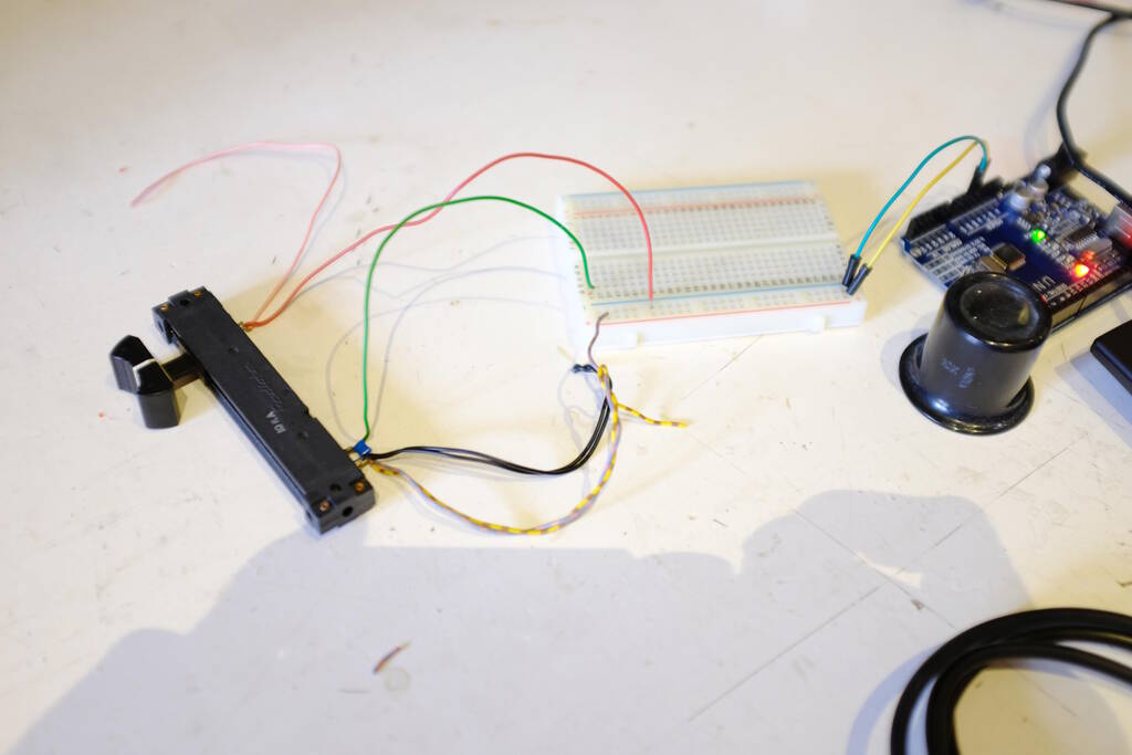
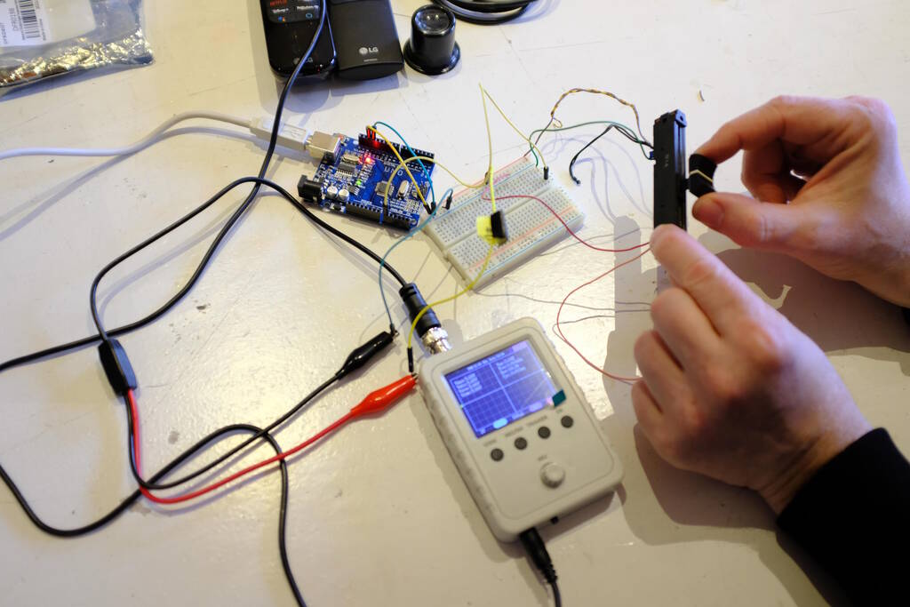
The blue capacitor led to the whole tangent into low pass and high pass filters. The wiring was a bit different from what we expected, but in the end we figured it out. Here you can see the whole set up using a small oscillator and measuring it on the Arduino:
A video that shows the change in voltage:
The code that we used to measure on the Arduino:
/*
 * Created by ArduinoGetStarted.com
 *
 * This example code is in the public domain
 *
 * Tutorial page: https://arduinogetstarted.com/tutorials/arduino-potentiometer
 */

float floatMap(float x, float in_min, float in_max, float out_min, float out_max) {
  return (x - in_min) * (out_max - out_min) / (in_max - in_min) + out_min;
}

// the setup routine runs once when you press reset:
void setup() {
  // initialize serial communication at 9600 bits per second:
  Serial.begin(9600);
}

// the loop routine runs over and over again forever:
void loop() {
  // read the input on analog pin A0:
  int analogValue = analogRead(A0);
  // Rescale to potentiometer's voltage (from 0V to 5V):
  float voltage = floatMap(analogValue, 0, 1023, 0, 5);

  // print out the value you read:
  Serial.print("Analog: ");
  Serial.print(analogValue);
  Serial.print(", Voltage: ");
  Serial.println(voltage);
  delay(1000);
}
The Rotary Encoder
The rotary encoder is an interesting device. Erwin explained how it works and based on that I think it has two small conducting plates on the knob that are offset a bit. One is for the clock signal and one for data. If the clock signal is high and data is high, you know it has turned one direction, if the clock signal is high and data is low, then you know it has turned in the other direction.
Erwin and I were experimenting with the code to make it work smoothly. It turned out that a small delay after you read a pin makes a large difference in measuring wrong turns:
#define PIN_CLOCK   2
#define PIN_DATA    3
#define PIN_SWITCH  4

uint8_t processed = 0;
uint8_t count = 127;

void setup() {
  pinMode(PIN_CLOCK, INPUT);
  pinMode(PIN_DATA, INPUT);
  pinMode(PIN_SWITCH, INPUT);
  Serial.begin(115200);
}

void loop() {
  if (digitalRead(PIN_CLOCK) == 0 && processed == 0) {
    delay(5);
    processed = 1;
    if (digitalRead(PIN_DATA) == 1) {
      Serial.println("linksom");
      count--;
    } else {
      Serial.println("rechtsom");
      count++;
    }
    Serial.println(count);
  }
  if (digitalRead(PIN_CLOCK) == 1) {
    delay(5);
    processed = 0;
  }
}
For example, one of the behaviors we experienced was that on a right turn, sometimes, it would also detect a left turn. We found that a delay of 5 ms was a good compromise.
Here you can see the code in action:
With a logic analyzer we can see the two signals interacting. On the left side you can see the clock first and data after that. This means that the rotary encoder is turned in one direction. On the right side, you can see the data first and then the clock signal indicating that the knob is turned the other way.
The rotary encoder could be pressed as a switch as well, but at first we couldn't get that to work. I was a bit confused because the rotary switch had three pull up resistors it seemed, but the one for the switch turned out to not have a resitors soldered on, so there was only a placeholder for a resistor. Enabling the Arduino's builtin pull up resistor on the pin of the switch did the trick, so:
pinMode(PIN_SWITCH, INPUT_PULLUP);
Measuring the Output of an Electric Guitar
I have an electric guitar and I was interested to try to record the signal from the guitar with a microcontroller and to play this back with a speaker. This allows me to build on the buzzer and to understand circuits for audio processing.
Spirals
There are various directions to investigate. First, I can try to simply read the signal from the guitar and show the read signal in the terminal. I can also try to record a couple of seconds (depening on how large the memory is) and play back these seconds on a speaker. Another spiral would be to make sure the speaker is driven in the right way with a D-class amplfier. Another direction is to perform an FFT analysis and create a guitar string tuner.
Circuits for Capturing Guitar Sounds
I studied various ways to measure the output of an electric guitar on a microcontroller but I saw many different circuits that I don't necessarily understand, for example this Stack Exchange post . So, I decided to take an advice from another web page and simply attach the guitar to the input of a microcontroller and start measuring.
Since I want to understand the effects of circuits as above, I think it actually makes sense for my case to do it in a crude way. It allows me to learn about the various problems. Before I attach the guitar directly to a pin on the microcontroller, I will make sure that the voltage and current are not too high for the microcontroller with an oscilloscope. I can imagine that I need to amplify or need to limit the current with a resistor.
Measuring the Output with an Oscilloscope
Attaching the guitar to the oscilloscope was very insightful. The following picture shows how I attached it:
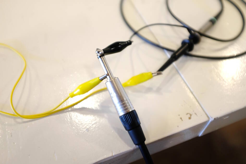
These are some pictures of the oscilloscope while I was trying to strum the guitar as loud as possible. Here I measure the current and it is clear that it goes little over 40 mA.
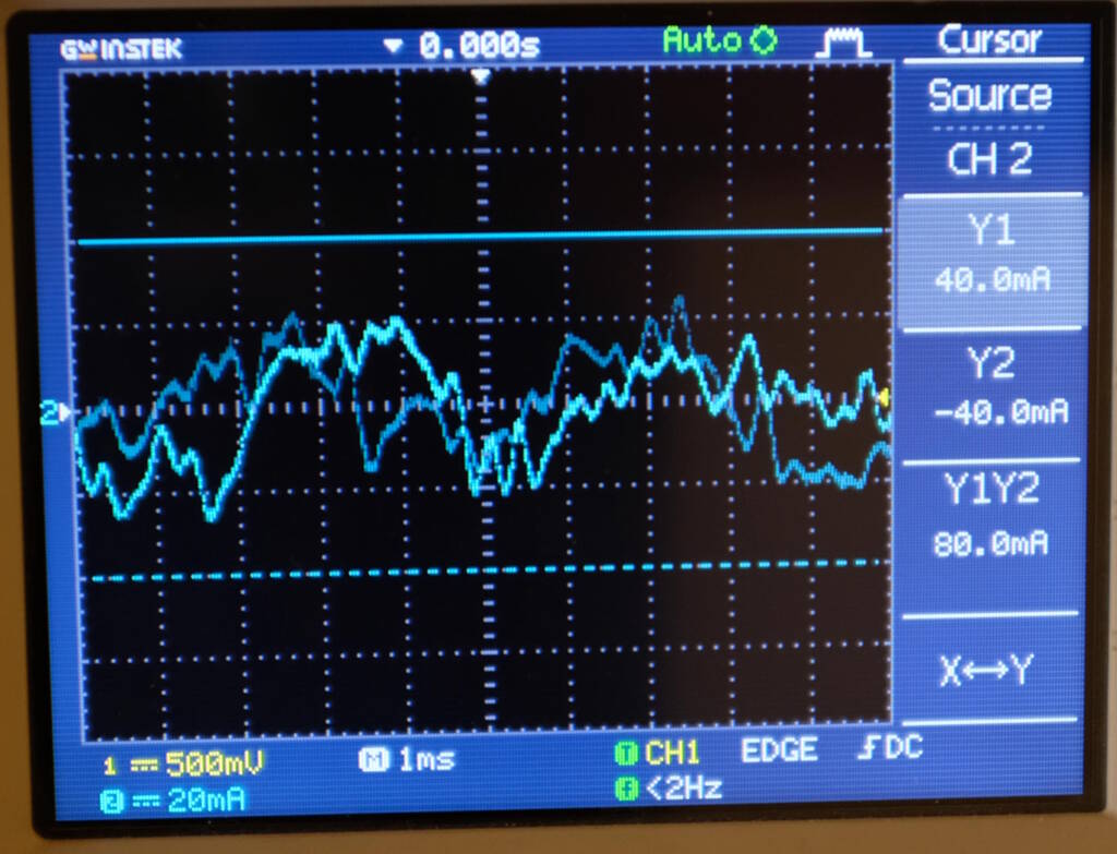
Here, I measure the voltage and it is clear that the bandwidth is about 1 V. So, perhaps it makes sense to measure with the 1V1 mode.
What this also revealed is that the signal is "centered". So, it is not the case that one pole of the guitar is ground and the other provides the signal. Instead, it is all about the difference between the two poles. So, this means that if I attach one of the outputs of the cable to ground and one to the pin, I miss half the signal, because the pin will measure from 0 (ground) to 3.3V.
This makes perfectly sense, because the output of the guitar is created by a string that manipulates a small magnet in the pickup that is wrapped in a coil. By changing the magnetic field in the coil, we create a signal. By the way, what is very interesting is that the coils around the six magnets for the six strings is only one wire. I think I always assumed that it would be a complicated circuit for each string but that is not the case.
Designing the Board
Although the 40 mA that the guitar generates may already be too high for the microcontroller, I decided that I don't need to add a dedicated resistor to limit the current because the guitar already has volume knob, a potentiometer that can limit the current perfectly well. I just have to be careful. I decided to simply attach the guitar to the ADC acting as if one of the poles of the wires is ground knowing that I miss half of the signal. This gives me a chance to understand and perhaps to also hear the ramifications.
In a previous board I used a simple unamplified piezo buzzer, but now I
want to use a dedicated speaker with an amplifier. Again, I prefer to have
the most simple amplifier possible to understand and to be able to hear the
shortcomings of this kind of amplification. I used
Neil's
hello.speaker.D11C
example
.
In the video he explains that this is a crude way to amplify a signal,
because the speaker is pulled to one extreme position and back to the
middle without being able to move to the other extreme position, so again,
for this type of amplification we lose half of the power.
Unfortunately, I can't say that I fully understand this circuit. One side of the speaker is connected to 5V from the USB and from this the chip is also powered with a voltage regulator bringing 5 V down to 3.3 V. I would have expected this end of the speaker to have been connected to ground (as Neil actually mentions in the video).
I guess, it doesn't matter as long as the other side of the speaker oscillates between 5V and 0V. In a sense, the speaker will experience a "reversed" signal then. My attempt to explain Neil's circuit:
At the bottom-left we have an N-channel MOSFET (
T1
) with the gate
connected to pin
1A05
on the D11C. This pin will give the PWM
signal to produce sound. The drain is connected to the speaker (
J3
) and the source is connected to ground. Unfortunately, it is
unclear which MOSFET Neil uses exactly, but I looked up the MOSFETs we have
and I used the
N-channel 30V
1.7A
that was also in the Fab KiCad library.
While writing this and trying to explain how it works, I noticed on this website that there are two types of N-channel MOSFETs, an enhancement type and a depletion type . Unfortunately, it is not clear what Neil used, but the one that I used is an enhancement type.
The enhancement type MOSFET works as follows: The MOSFET delivers current between drain and source if there is a sufficient voltage across the drain and source and if there is a sufficient (typically lower) voltage across gate and source. Now, it all makes sense: There is a voltage across the speaker because one side is powered by 5V and the other side is connected to the drain. If the gain receives a high signal, this will allow current to flow from the drain to the source which is connected to ground. Since there is a voltage across the speaker, the speaker "drives" this current to flow from drain to source. As soon as the signal between gate and source is low (by means of PWM), the drain to source current is blocked.
So, I copied this setup and designed my schematic in the same way using the RP2040:

On port
D0
that can act as an analog port
A0
, I have the
input for the guitar. As the input is connected to ground, there will be
negative inputs to
A0
as well, something that the will not be
recorded then. Pins
D3
and
D5
have a green and red LED
respectively that will indicate whether the device is recording or playing
back. At the bottom we have the speaker powered by 5V. The other side is
connected to the drain of the MOSFET and the source is connected to ground.
The gain is connected to pin
D10
that will provide the PWM signal.
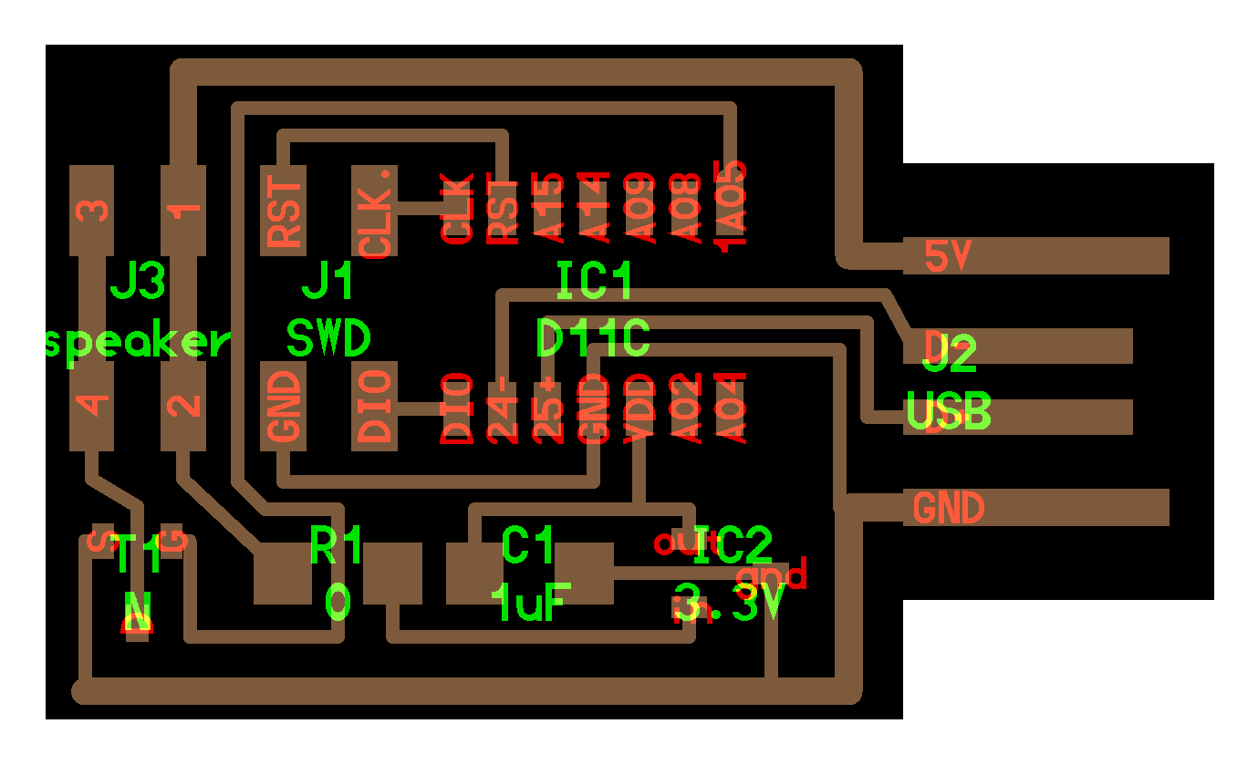
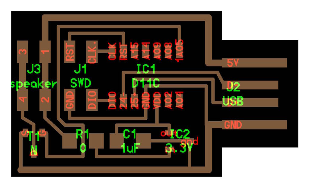
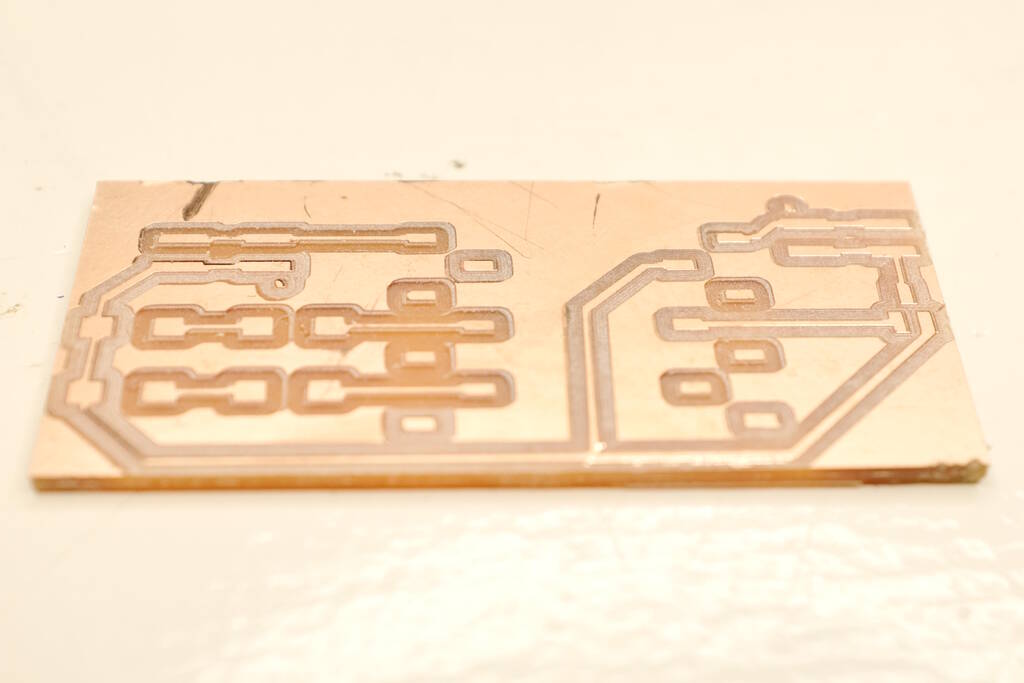
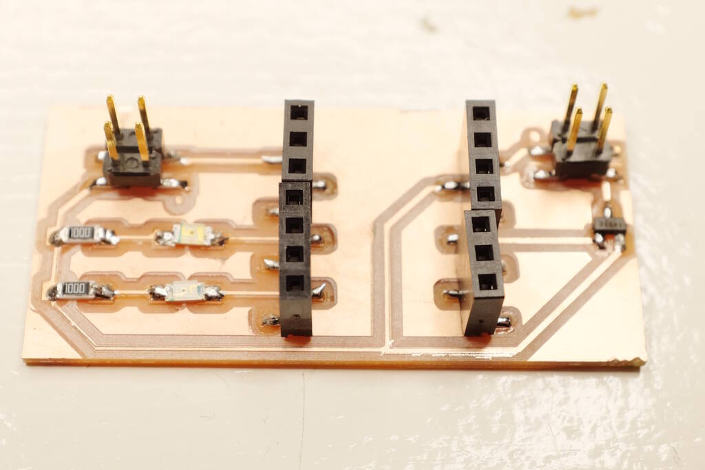
This is an overview of the board:

Producing the Board
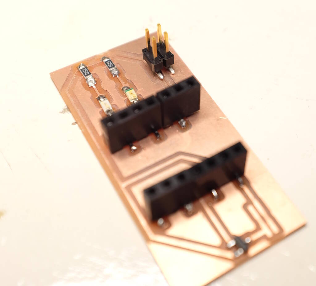
I had the following issues producing the board. Firstly, I accidentally chose the pin header 2x02 with a pitch of 1.27 mm instead of the one with a pitch of 2.54. I discovered this right before I wanted to solder the connectors on the board... This is an expensive mistake in terms of time, so I vow to double check the footprints before milling the board. Here you can see the connector that does not fit:
Secondly, I had the problem that milling the traces was not deep enough. I discussed this with Michelle and she could somehow see that my mill bit was not touching the copper surface. She asked me if I had held down the mill bit while fixating the little screw, which I did, but she showed me how she did this and I came to the conclusion that my technique is most likely not sufficient. I hold one finger against the mill bit while fixating the screw, but Michelle grabs the mill bit with two fingers and actively pushes down while fixating the screw. We came to the conclusion that with my technique there is most likely not enough pressure to fully hold down the mill bit.
She also advised to simply use the conical mill bit. After I used this mill bit and used her technique, the board was fine:
Finding a Matching Speaker
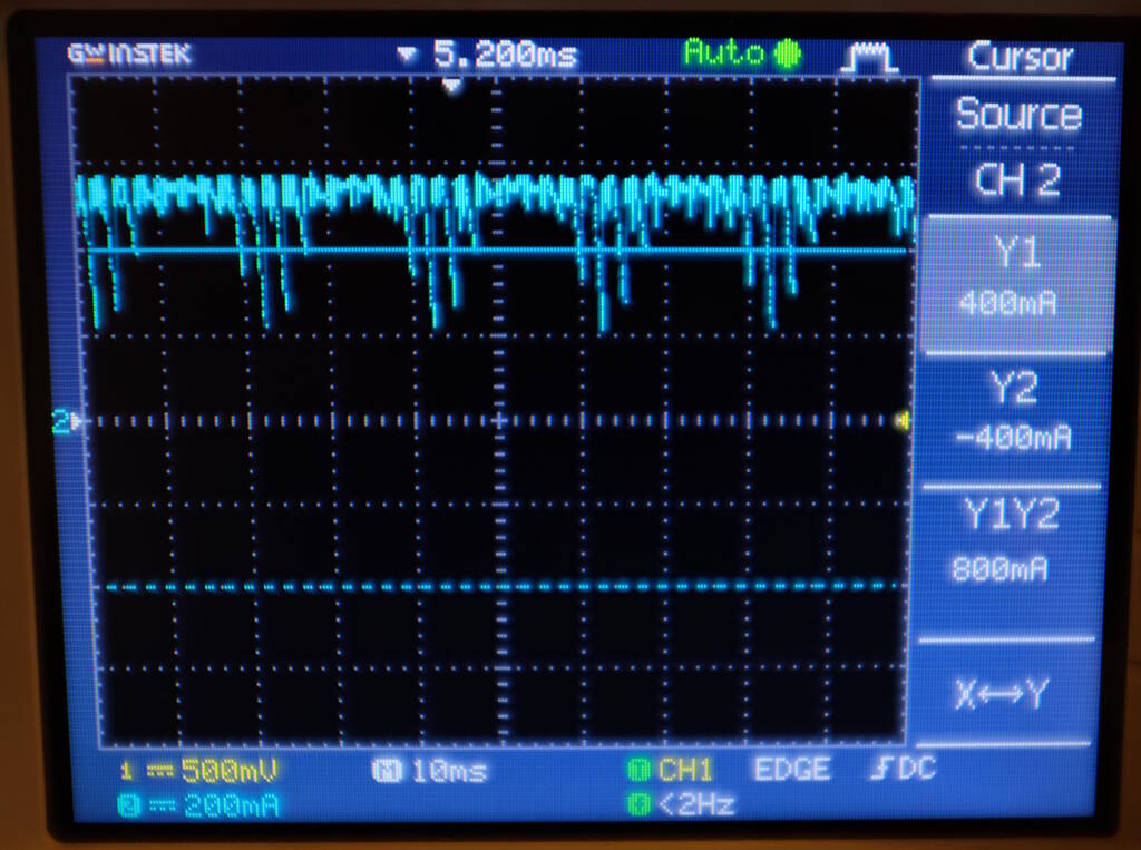
Before I connect a speaker, I want to understand what speaker to connect. I have an 8 Ohm 5 W speaker, a 8 Ohm 0.5 W speaker. At Waag we have an 8 Ohm 1 Watt speaker and there is a bag with all kinds of speakers. So, I decided to play my program that dims a tone and analyze it with an oscilloscope to find out what kind of power the "amplifier" has.
In the following image you can see that the current is about 600 mA:
In the following image you can see that the voltage is about 5.67 V:
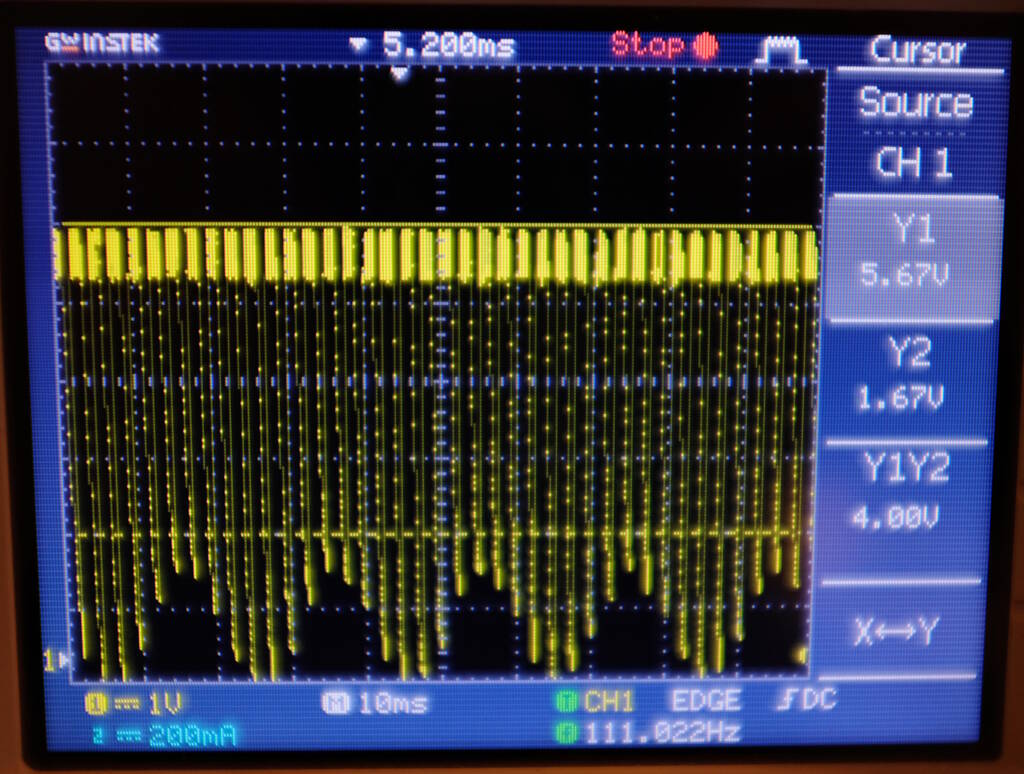
This means that the power P = VI = 5.67 * 600 mA = 3.4 W. Therefore, I chose to use the 5W 8 Ohm speaker:
Driving the Speaker with Dimming a Tone
The first test was to drive the speaker with the program that "dims" a tone. This worked!! I have amplification! I don't know if it is visible but the speaker actually moves a bit across the table:
Playing a Wave File
The sound above does not sound too bad and Neil explained that this crude way of amplification is not that bad for a simple tone. Let's see what happens if we play an actual wave file. This allows us to understand and hear how suboptimal this amplifier is.
For the tone that you hear above, the sample frequency is 48 kHz, it is 20 times oversampled (so 20 pulses for each sample). This amounts to a wrap value of 130:
system clock: 125000000
sample rate: 48000
oversampling factor: 20
wrap: 130
This means that each sample should be between 0 and 128 where 128 means the full volume and 0 means no sound. I made sure that the samples of the wave are between 0 and 256. I will divide by two while playing the wave. I took a wave file, edited the wave file in Audacity to make it mono and have a sample frequency of 48 kHz and export it as an unsigned 8-bit Wave file.
Based on this information I adapted the wav2c program to read these samples and create an array in C. I was running out of time, so I did it fast and sloppy. This is the diff:
/home/pieter/personal/git/w/wav2c [my-adaptation]                            xps
$ git diff master
diff --git a/main.c b/main.c
index c118515..706f4d7 100644
--- a/main.c
+++ b/main.c
@@ -26,17 +26,18 @@ typedef struct {
 uint32_t numOfSamples = 0;
 int32_t lowLimit;
 int32_t highLimit;
-int16_t * leftChannel = NULL;
-int16_t * rightChannel = NULL;
+uint8_t * leftChannel = NULL;
+uint8_t * rightChannel = NULL;

 uint16_t DAC_max = 4096;
 uint16_t DAC_shift = 2048;

 /// DAC resolution set for C format
-uint16_t ConvertToDACValue(int16_t value)
+uint8_t ConvertToDACValue(int8_t value)
 {
-  uint32_t tmp = ((value*DAC_max)/highLimit) + DAC_shift;
-  return tmp;
+  /* uint32_t tmp = ((value*DAC_max)/highLimit) + DAC_shift; */
+  /* return tmp; */
+  return value;
 }


@@ -101,7 +102,7 @@ void printfHeader(sWavHeader * header)
   printf("--------------------------------------.\n");
 }

-void fprintfChannel(FILE *pFile , int16_t * array, uint32_t size)
+void fprintfChannel(FILE *pFile , uint8_t *array, uint32_t size)
 {
   for (uint32_t i = 0; i<size; ++i)
   {
@@ -122,8 +123,8 @@ void readWavData(int fileId, sWavHeader * header)
   numOfSamples = header->Subchunk2Size / (header->NumChannels * header->BitsPerSample/8);
   switch (header->BitsPerSample) {
     case 8:
-      lowLimit = -128;
-      highLimit = 127;
+      lowLimit = 0;
+      highLimit = 255;
       break;
     case 16:
       lowLimit = -32768;
@@ -136,21 +137,21 @@ void readWavData(int fileId, sWavHeader * header)
   }


-  leftChannel = malloc(sizeof(uint16_t) * numOfSamples);
+  leftChannel = malloc(sizeof(uint8_t) * numOfSamples);
   if (header->NumChannels > 1)
   {
-    rightChannel = malloc(sizeof(uint16_t) * numOfSamples);
+    rightChannel = malloc(sizeof(uint8_t) * numOfSamples);
   }

   /// read all music data
   for (uint32_t i = 0; i<numOfSamples; ++i)
   {
-    read(fileId, &leftChannel[i], sizeof(uint16_t));
+    read(fileId, &leftChannel[i], sizeof(uint8_t));
 //    swapEndiannesS16(&leftChannel[i]);
     // check if value was in range
     if ((leftChannel[i] < lowLimit) || (leftChannel[i] > highLimit))
     {
-      printf("**value out of range\n");
+      printf("**value out of range: %u\n", leftChannel[i]);
     }

     if(header->NumChannels > 1)
@@ -166,7 +167,7 @@ void readWavData(int fileId, sWavHeader * header)
   }
 }

-void writeAsCFile(int16_t *leftChannel, int16_t *rightChannel,  sWavHeader * header)
+void writeAsCFile(int8_t *leftChannel, int8_t *rightChannel,  sWavHeader * header)
 {
   FILE * pFile;
   pFile = fopen("sound.c","w");
@@ -178,7 +179,7 @@ void writeAsCFile(int16_t *leftChannel, int16_t *rightChannel,  sWavHeader * hea

   /// printf left Channel
   fprintf(pFile, "const size_t leftChannelSize = %d;\n",numOfSamples);
-  fprintf(pFile, "const uint16_t leftChannel[] = {\n");
+  fprintf(pFile, "const uint8_t leftChannel[] = {\n");
   fprintfChannel(pFile, leftChannel, numOfSamples);
   fprintf(pFile, "};\n");

@@ -192,7 +193,7 @@ void writeAsCFile(int16_t *leftChannel, int16_t *rightChannel,  sWavHeader * hea
   fclose(pFile);
 }

-void writeAsMatlabFile(int16_t *leftChannel, int16_t *rightChannel,  sWavHeader * header)
+void writeAsMatlabFile(int8_t *leftChannel, int8_t *rightChannel,  sWavHeader * header)
 {
   FILE * pFile;
   pFile = fopen("sound.m","w");
@@ -240,7 +241,7 @@ int main(int argc, char * argv[])
     close(file);

     writeAsCFile(leftChannel, rightChannel, &wavHeader);
-    writeAsMatlabFile(leftChannel, rightChannel, &wavHeader);
+    //writeAsMatlabFile(leftChannel, rightChannel, &wavHeader);

     return 0;
 }
(END)
   fprintf(pFile, "};\n");

@@ -192,7 +193,7 @@ void writeAsCFile(int16_t *leftChannel, int16_t *rightChannel,  sWavHeader * hea
   fclose(pFile);
 }

-void writeAsMatlabFile(int16_t *leftChannel, int16_t *rightChannel,  sWavHeader * header)
+void writeAsMatlabFile(int8_t *leftChannel, int8_t *rightChannel,  sWavHeader * header)
 {
   FILE * pFile;
   pFile = fopen("sound.m","w");
@@ -240,7 +241,7 @@ int main(int argc, char * argv[])
     close(file);

     writeAsCFile(leftChannel, rightChannel, &wavHeader);
-    writeAsMatlabFile(leftChannel, rightChannel, &wavHeader);
+    //writeAsMatlabFile(leftChannel, rightChannel, &wavHeader);

     return 0;
 }
This is part of the output of the sound represented in a C array:
const size_t leftChannelSize = 143927;
const uint8_t leftChannel[] = {
125, // 125
125, // 125
125, // 125
125, // 125
125, // 125
125, // 125
125, // 125
124, // 124
124, // 124
123, // 123
123, // 123
124, // 124
123, // 123
123, // 123
124, // 124
124, // 124
123, // 123
123, // 123
123, // 123
124, // 124
124, // 124
123, // 123
123, // 123
123, // 123
123, // 123
123, // 123
Playing this file sounds as follows:
Not too bad! It is a bit soft and there are pops but the sound that you hear is more or less what it should be.
Recording the Guitar
I figured out how many seconds the RP2040 can record which is about 3
seconds and I created an array of
uint8_t
of 48 kHz times 3 seconds
is 144000 bytes. The code is below:
#include "pico/stdlib.h"
#include <stdio.h>
#include "hardware/pwm.h"
#include "hardware/clocks.h"
#include "hardware/adc.h"
#include "../xiao_rp2040.h"

// #include "sound.h"

#define NR_SAMPLES_SOUND 144000

#define PIN_SPEAKER D10
#define PIN_PLAY D3
#define PIN_RECORD D5

// the pin we are using for analog
#define INPUT_GUITAR 0
// the pin for the first port
#define PIN_ANALOG A0 + INPUT_GUITAR

#define SAMPLE_RATE 48000
#define OVERSAMPLING_FACTOR 20

#define NOTE_HZ 400

#define BITS_ADC 12
#define BITS_SPEAKER 7

uint8_t sound[NR_SAMPLES_SOUND];

uint16_t compute_wrap() {
  return (uint16_t) (clock_get_hz(clk_sys) / (SAMPLE_RATE * OVERSAMPLING_FACTOR));
}

// a wrap will occur 960000 times per second
void on_pwm_wrap_sound() {

  static int recording = 1;
  static int nr_wraps = 0;
  static int sample = 0;

  // Clear the interrupt flag that brought us here
  pwm_clear_irq(pwm_gpio_to_slice_num(PIN_SPEAKER));

  if (nr_wraps == 0) { // this happens once every 48000 times
    if (recording) {
      uint adc_raw = adc_read();
      sound[sample] = adc_raw /*>> (BITS_ADC - BITS_SPEAKER)*/;
    }
    else {
      // set the level
      pwm_set_gpio_level(PIN_SPEAKER, sound[sample]);
    }
    sample++;
  }

  if (nr_wraps == OVERSAMPLING_FACTOR - 1) {
    // set the number of wraps to zero
    nr_wraps = 0;
  }
  else {
    nr_wraps++;
  }

  if (sample == NR_SAMPLES_SOUND - 1) {
    sample = 0;
    recording = !recording;
    if (recording) {
      pwm_set_gpio_level(PIN_SPEAKER, 0);
      gpio_put(PIN_RECORD, 1);
      gpio_put(PIN_PLAY, 0);
    }
    else {
      gpio_put(PIN_RECORD, 0);
      gpio_put(PIN_PLAY, 1);
    }
  }
}


int main() {
  stdio_init_all();

  adc_init();
  adc_gpio_init(PIN_ANALOG);
  adc_select_input(INPUT_GUITAR);

  gpio_init(PIN_PLAY);
  gpio_set_dir(PIN_PLAY, GPIO_OUT);

  gpio_init(PIN_RECORD);
  gpio_set_dir(PIN_RECORD, GPIO_OUT);

  // Tell the pin that the PWM is in charge of its value.
  gpio_set_function(PIN_SPEAKER, GPIO_FUNC_PWM);

  // Figure out which slice we just connected to the LED pin
  uint slice_num = pwm_gpio_to_slice_num(PIN_SPEAKER);

  pwm_clear_irq(slice_num);
  pwm_set_irq_enabled(slice_num, true);
  irq_set_exclusive_handler(PWM_IRQ_WRAP, on_pwm_wrap_sound);
  irq_set_enabled(PWM_IRQ_WRAP, true);

  // Get some sensible defaults for the slice configuration. By default, the
  // counter is allowed to wrap over its maximum range (0 to 2**16-1)
  pwm_config config = pwm_get_default_config();

  // set the wrap value a little bit higher than 128, so we can use this number
  // and we will never reach a 100% duty cycle
  uint16_t wrap = compute_wrap();

  pwm_config_set_wrap(&config, wrap);
  pwm_init(slice_num, &config, true);

  sleep_ms(3000);

  printf("system clock: %d\n", clock_get_hz(clk_sys));
  printf("sample rate: %d\n", SAMPLE_RATE);
  printf("oversampling factor: %d\n", OVERSAMPLING_FACTOR);
  printf("wrap: %d\n", wrap);


  while (1) {
    tight_loop_contents();
  }
}
I initially bitshifted the 12 bits sample from the ADC to a 7 bit value to keep within this range of 130 in the following way:
      uint adc_raw = adc_read();
      sound[sample] = adc_raw >> (BITS_ADC - BITS_SPEAKER);
However, visualizing the recorded samples, it turned out that if I put the volume on my guitar to 6 that it stays within the 0-128 range, so I commented out the bit shifting.
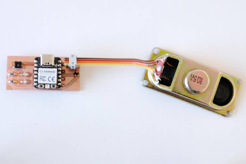
The resulting setup is here:
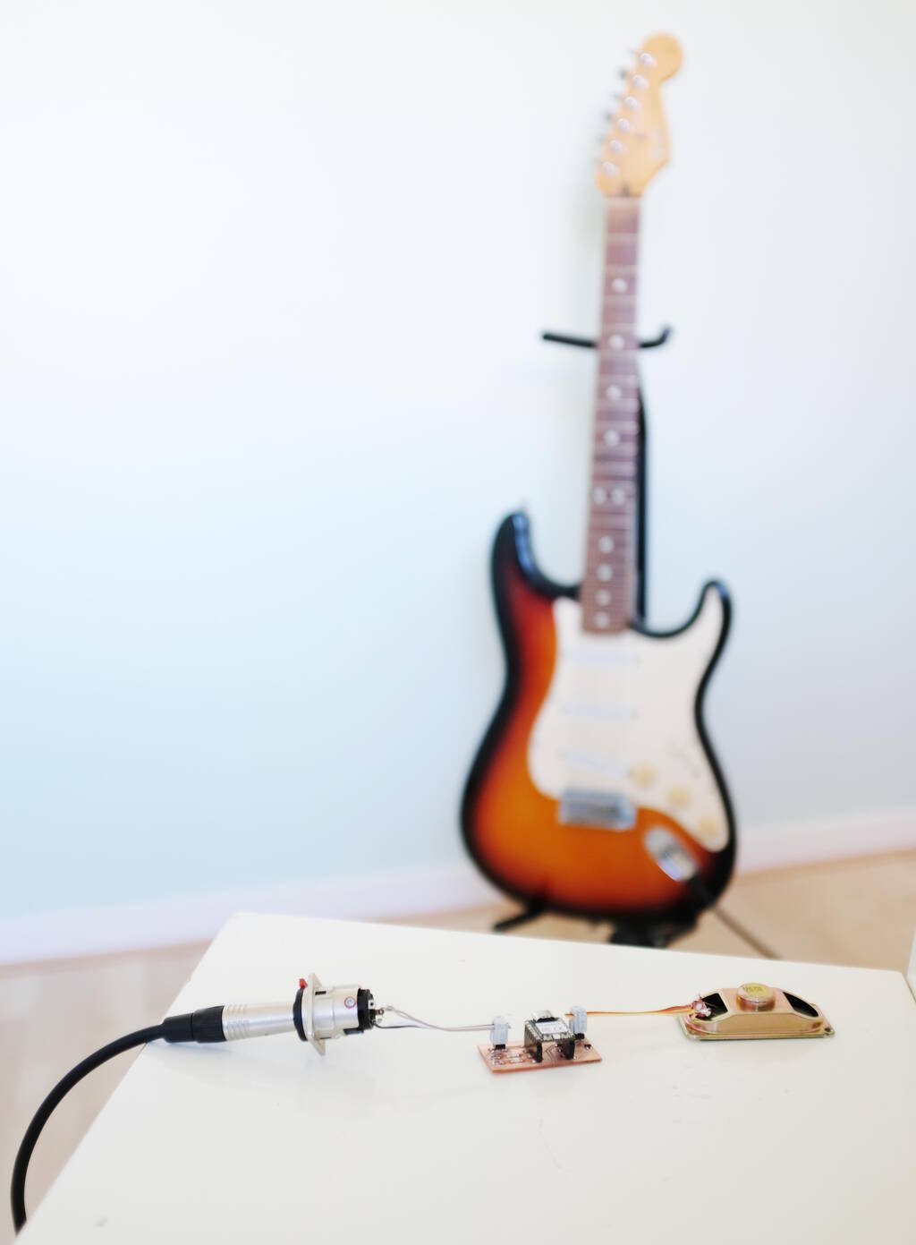
Recording and playing back is here:
The sound is distorted and the frequency is too high. The distortion can most likely be explained by the fact that I miss half of the signal. The frequency that is too high is more difficult to explain but I think that sampling takes longer than the period between the pulses of 48 kHz. In the future I can try to lower the sample frequency and experiment with that.
Additionally (I don't know if that is apparent in the video), there is quite some noise. Perhaps a low pass filter can solve this.
Reflections
I learned a lot and I liked the approach that I took because I have something to iterate on and compare the difference in sound. As soon as I have more time for this, I think I will do the following iterations:
- Experiment with the sample rate and the maximum values, for example using 8 bits instead of 7 bits. I have 44.1 kHz in mind with 11 times oversampling giving me a warp value of about 258.
- Improve the speaker by finding a way to drive "both sides". Essentially, I think I'm creating a class-D amplifier then.
- Use a simple circuit with resistors to divide the voltage to read the positive and negative signal from the guitar.
- Use low-pass filters to filter out the noise and the high frequencies that you get from over sampling.
Tasks
Fab Academy
- Probe the analog and digital signals of input devices.
- Attach a sensor to a microcontroller and measure it.
- Demonstrate workflows used in sensing something with input device and MCU board.
- Documente how the physical property relates to the measured results.
- Document your design and fabrication process.
- Explain the programming processes you used.
Personal
- Experiment with the sample rate and the maximum values.
- Improve the amplification.
- Improve the circuit with a voltage divider to meaure the guitar signal correctly.
- Add low pass and high pass filters to improve the audio.