Measuring the Power Consumption of Output Devices
For the group assignment, we measured the power consumption of two different motors in various ways. We tested a servo motor and a stepper motor. We measured with a power unit that can monitor current and voltage, and we measured by using a multimeter measuring voltage and current. At the time of measuring we assumed we had to measure only the power, but later it became apparent that we had to measure the power consumption . I decided to focus on that using the graphs that were produced on Henk's laptop while measuring the power.
The Servo Motor
The servo motor was a MG995 that could take an input voltage between 4.8 and 7.2 V. We attached it to the power source such that we could monitor it and the two graphs below came out.
Power consumption is measured kWh or Joules which is Ws, so power times
time and power
P = V * I
, so I will take a period from the graph and
compute the power consumption by multiplying the voltage with the current
and multiply that with the number of seconds of that period. The measuring
frequency of the power source is once per second. We cannot accurately
measure power consumption because of potential peaks within the second, but
let's assume that the device shows the average value within that a second.
Computing the values over the time period will then be an approximation of
the real value.
In the first graph, there is no load from period 0 to about 60 s and then load from period 70 s to 80 s:
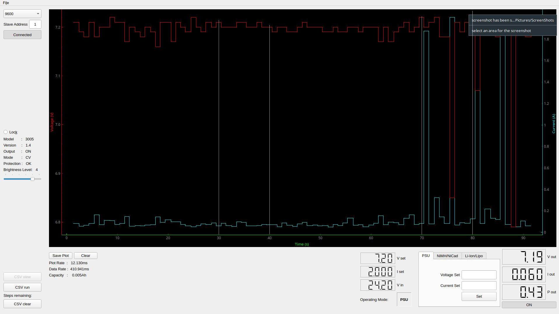
So, let's measure the power consumption in period 30 s to 40 s and from 70 s to 80 s. I loaded the graph in GIMP, checked on which y-coordinate of a pixel the value was a low value, on which it was a high value, which allowed me to compute the values. For example, for the graph above for current, the tick for value zero is at y-coordinate 797, while for the value 1.8 A, the y-coordinate is 134. We can then compute the current with the following program that takes as input the low value, the corresponding y coordinate of the pixel, the high value and its corresponding pixel and the y-coordinate of the value we want to compute:
(defun compute-value (value-low y-low value-high y-high y)
  "Given a y-coordinate, compute the value.

The value is computed according to low and high values and the corresponding y
coordinates of those low and high values."
  (let ((range-y (- y-high y-low))
	(range-val (- value-high value-low))
	(y-corrected (- y y-low)))
    (+ (/ (* y-corrected range-val) range-y)
       value-low)))
I did this as well for the voltage and then I simply recorded 10 samples (y-coordinates) for current and voltage. In GIMP, I added cross lines to make an accurate reading for the period and then I recorded the y values for current and voltage for 10 samples. For the graph above these are for "no load" and "under load" respectively:
(defparameter *y-v-no-load* '(76 93 93 93 76 76 93 93 76 93))
(defparameter *y-i-no-load* '(775 766 774 777 761 763 775 775 774 770))

(defparameter *y-v-load* '(59 93 76 59 126 126 679 76 109 76))
(defparameter *y-i-load* '(767 106 768 678 744 767 59 772 764 766))
To compute the power, I use the following function that takes as input samples for current and voltage and computes the power over time:
(defun power-consumption (y-Vs y-Is)
  "compute the power consumption over voltage and current samples.

The voltage and current samples are expressed in terms of y-coordinates.  From
this we compute the actual values, compute the power for each sample and sum it
acquire the power consumption."
  (let* ((vs (mapcar #'(lambda (y)
			(compute-value *v-low* *y-v-low* *v-high* *y-v-high* y))
		    y-Vs))
	 (is (mapcar #'(lambda (y)
			(compute-value *i-low* *y-i-low* *i-high* *y-i-high* y))
		    y-Is))
	 (ps (mapcar #'* vs is)))
    (reduce #'+ ps)))
The power consumption for no load (30 to 40 s) is 5.1 J, for under load (70 to 80 s) it is 34.1 J.
The Stepper Motor
For the stepper motor, the load is more continuous:
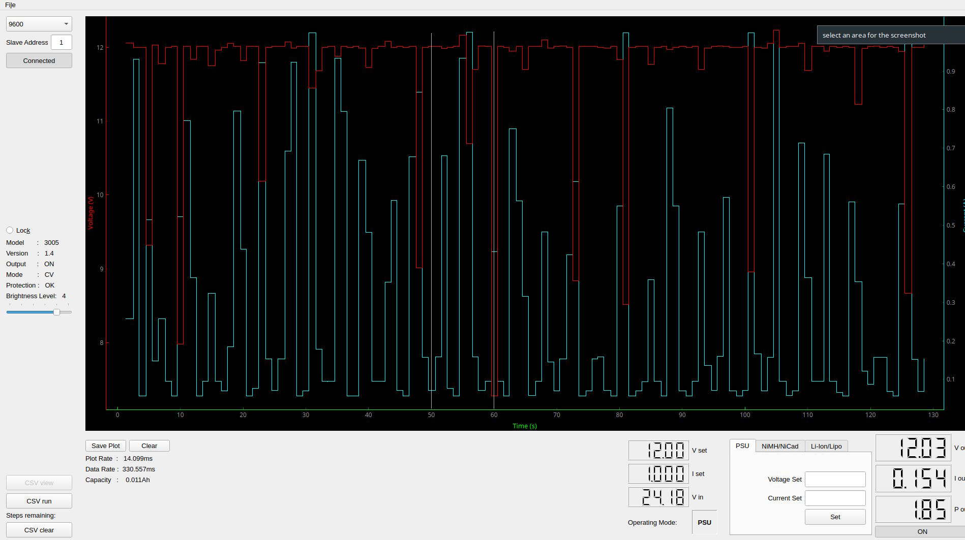
I recorded the load over period 50 to 60 s and recorded as power consumption 38.4 J.
The parameters and samples are encoded below:
;; Graph stepper
(let ((*y-v-low* 674)
      (*v-low* 8)
      (*y-v-high* 93)
      (*v-high* 12)

      (*y-i-high* 140)
      (*i-high* 0.9)
      (*y-i-low* 746)
      (*i-low* 0.1))

  (defparameter *y-v* '(91 91 95 93 91 69 282 136 90 91))
  (defparameter *y-i* '(768 702 306 764 779 114 63 702 768 750))

  (print-result 50 60 (power-consumption *y-v* *y-i*)))
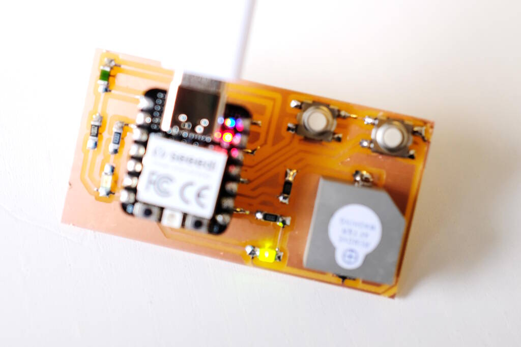
Improve Last Week's Design
To make last week's board work properly, I will redesign the board from last week. I will change the following things:
- use a green LED for the eyes,
- use an NTC thermistor,
- make the pads bigger for the buzzer,
- connect the components to more convenient pins,
- connect everything to 3.3 V, and
- use pull up resistors for the buttons.
The new schematic has a different pin assignment for easier routing with the buttons connected to ground for using pull up resistors, uses a green LED and an NTC thermistor, and uses 3.3 V.

It was difficult to make the board smaller because I didn't have the correct buzzer footprint and I wanted the termistor on the left side of the microcontroller and the buttons on the right side. The pads for the buzzer are a bit more wide for ease of soldering. The traces are now less complex:

The milling didn't work well because the plate was clearly not well attached to the sacrificial plate. I changed to a new plate, made sure that it was very tight. One attempt went wrong because I zeroed the Z on the corner but that was a bit elevated. So, when leveling on a bit more reprensentative piece of the board, the milling went well, except for one corner of the board where the milling bit didn't cut through the copper fully. The only explanation that I have is that the copper plate had an imperfection there and was a bit thinner. The bottom right corner is where you can see that the milling bit was engraving rather than milling:
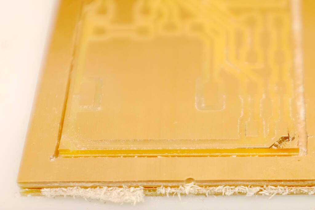
I tried to scrape the copper off but this was more difficult than I thought. It turned out that it was a lead to ground, so it didn't matter.
A Simple PWM Library
I wanted to understand well how Pulse-Width Modulation works, so I decided to create my own small software PWM library. This means that I will make use of the main busy-wait loop and turn on and off pins "manually". First, I want to test to what extent this works and measure how fast it can switch.
Measure Switching in the Main Loop
I will try to measure and approximate, how fast I can switch on and off a pin on the RP2040. For that, I will loop a million times in which I switch on and off the pin with a delay that is as small as possible. I will then measure the duration of the loop and compute how fast it switches and to what extent there is overhead, for example because of iterating in the loop. The complete code is as follows:
#include <stdio.h>
#include "pico/stdlib.h"
#include "hardware/gpio.h"
#include "../xiao_rp2040.h"

const uint PIN_LED = D7;

int main() {
  stdio_init_all();

  gpio_init(PIN_LED);
  gpio_set_dir(PIN_LED, GPIO_OUT);

  uint64_t start = time_us_64();
  for (int i = 0; i < 1000000; i++) {
    gpio_put(PIN_LED, 1);
    sleep_us(1);
    gpio_put(PIN_LED, 0);
    sleep_us(1);
  }
  uint64_t end = time_us_64();

  // wait for the IO terminal to be available
  sleep_ms(3000);

  printf("100000 iterations took %lld us\n", end - start);

  while (true) {
    tight_loop_contents();
  }
}
In a perfect world where iterating and doing the function calls takes no time, the period would be 2 us, which is equivalent to 500 kHz. The duration of the loop with a million iterations would then 2000 ms. The measured time, however is 2425 ms, which means that there is about 20% overhead for a frequence of 500 kHz. The overhead will become less relatively with a lower frequency, so this is fine for my purposes.
Dimming an LED
With this information, I can create a software PWM function that I will use to dim an LED:
void my_pwm(uint pin, uint frequency, double duty_cycle) {
  uint period_us = 1000000 / frequency;
  uint period_on_us = floor(duty_cycle * period_us);
  uint period_off_us = floor((1 - duty_cycle) * period_us);

  while (1) {
    gpio_put(pin, 1);
    sleep_us(period_on_us);
    gpio_put(pin, 0);
    sleep_us(period_off_us);
  }
}

int main() {
  stdio_init_all();

  gpio_init(PIN_LED);
  gpio_set_dir(PIN_LED, GPIO_OUT);

  my_pwm(PIN_LED, 10, 0.5);
}
You can see here, that I'm blinking an LED with a frequency of 10 Hz with a duty cycle of 10:
The human eye scans at about 30 Hz, so with a frequency of 100 Hz, I should experience it as a continuous light and hopefully my camera will as well. Let's make it bright first with a duty cycle of 95 %:
my_pwm(PIN_LED, 100, 0.95);
Then with a duty cycle of 5 %:
my_pwm(PIN_LED, 100, 0.05);
Driving the Buzzer
Now that we have this, I want to drive the buzzer as well, but for the buzzer it would be nice to be able to control the duration as well, so let's adapt the PWM library with a time duration:
void my_pwm(uint pin, uint frequency, double duty_cycle, uint duration_ms) {
  uint period_us = 1000000 / frequency;
  uint period_on_us = floor(duty_cycle * period_us);
  uint period_off_us = floor((1 - duty_cycle) * period_us);
  uint nr_iterations = floor((1000 * duration_ms) / period_us);

  for (int i = 0; i < nr_iterations; i++) {
    gpio_put(pin, 1);
    sleep_us(period_on_us);
    gpio_put(pin, 0);
    sleep_us(period_off_us);
  }
}
Now, let's have the buzzer ring on 400 Hz for 10 seconds:
my_pwm(PIN_BUZZER, 400, 0.5, 10000);
As opposed to an LED, the duty cycle for sound has a different effect and does not control how loud the buzzer is. Instead it changes the tone of the sound.
The reason that an LED dims with smaller duty cycles is that if you provide it with a constant high signal, the LED will light up. If you do the same with a speaker, you will only hear one tick. A speaker needs a constantly changing signal to sound. Since differing durations of the duty cycle change the blocked waveform, different overtones will sound through, therefore changing the sound. Let's see if we can test this. We will sound a tone of 400 Hz with different duty cycles:
      my_pwm(PIN_BUZZER, 400, 0.1, 2000);
      my_pwm(PIN_BUZZER, 400, 0.2, 2000);
      my_pwm(PIN_BUZZER, 400, 0.3, 2000);
      my_pwm(PIN_BUZZER, 400, 0.4, 2000);
      my_pwm(PIN_BUZZER, 400, 0.5, 2000);
Play a Song
Let's play a simple song making use of the
my_pwm()
function. First
we define a
note()
and
rest()
function:
void note(uint note, uint duration_ms, uint rest_ms) {
  my_pwm(PIN_BUZZER, note, 0.5, duration_ms);
  sleep_ms(rest_ms);
}

void rest(uint duration_ms) {
  sleep_ms(duration_ms);
}
We define some notes defining their frequencies:
#define A 440
#define E 330
#define F 349
#define GIS 415
We then define the song:
void song() {
  note(A, 300, 200);
  note(E, 230, 100);
  note(E, 110, 50);

  note(F, 300, 200);
  note(E, 300, 200);
  rest(500);
  note(GIS, 300, 200);
  note(A, 300, 200);
  rest(500);
}
Playing the song yields:
Using the RP2040 PWM Library
We would now like to do the same, but then using the PWM library. Playing a a simple tone is not so difficult, but playing sound properly is more challenging. In this section I investigate this.
Playing a Simple Tone
You have to set the frequency in terms of the frequency of the system bus, which turns out to be 125 MHz:
printf("Clock: %d\n", clock_get_hz(clk_sys));
The frequency can be manipulated with essentially two ways: a counter that counts up to a number TOP and then wraps. By default the value of TOP is 2^16-1 which is 65535. At each tick of the system bus, this counter is updated. The frequency of 125 MHz can be divided by a value up to 256, so the frequency of the PWM for the default values of 65355 and 125 MHz yield a period of 1 / 125e6 = 8 ns * 65356 = 0.524 ms, which is a frequency of 1907 Hz.
We can lower the frequency to 400 Hz with the following code (1907 / 400 = 4.77):
      // Get some sensible defaults for the slice configuration. By default, the
      // counter is allowed to wrap over its maximum range (0 to 2**16-1)
      pwm_config config = pwm_get_default_config();
      // Set divider, reduces counter clock to sysclock/this value
      pwm_config_set_clkdiv(&config, 4.77f);
Suppose we want a duty cycle of 50%, we have to write 65356 / 2:
      // set the level to half of the counter to get a 50% duty cycle.
      pwm_set_gpio_level(PIN_BUZZER, 65356/2);
I don't have a recording of this but it works as expected.
Dimming a tone
I wanted to check whether I can dim a tone in the same way as dimming an LED but then with varying the duty cycle. This was more complex than I thought and the crucial thing to realize is that there are two different periods in play that are independent. First, we have the period of the tone we want to play, so the period of 400 Hz. Then we have the period of "dimming" the tone. Those two periods are independent but they both need to be tracked in more or less the same function. I ended up making two counters for each period and when the counter hits the right target value, I adjust a value.
Determining Constants
As said above, the frequency of the system bus is 125 MHz, which means that a counter is increased each 8 ns. For this code, I didn't want to decrease the frequency but I needed to play with the TOP value on which the counter wraps. Since one of my goals is to play a Wave file at some point, I wanted to work with a representative sampling frequency such as 44.1 kHz or 48 kHz. (Humans hear between 20 and 20000 Hz, and the laws from Nyquist and Shannon state that we need to oversample with a factor of 2 to be able to hear a certain frequency. Since 20 kHz is the highest frequency we can hear, we need at least a sample frequency of 40 kHz.)
To be able to dim a tone we need to oversample each sample with a factor 10 or so to make sure that in these oversampled samples, we have room to play with the duty cycle to change the volume of the tone.
I chose a sample rate of 48 kHz and an oversampling factor of 20 to get a wrap value of system frequency / (48 kHz * 20) = 125 MHz / (48 kHz * 20) = 130. This is a nice value because it it allows me to have an almost full duty cycle with a value of 128 (7 bits), giving me a high volume of the tone. This allows me to vary the volume of the tone by setting the PWM level to 128 (loud) or to 0 (no tone).
So, suppose we want to play a tone on full volume, we set the level to 128. The counter is counting towards 130 and as long as the counter is below the level that we set, in this case 128, it will give a high signal. For the values above 128 it will give a low signal. This will give us a duty cycle of 128 / 130 * 100 = 98%.
Suppose we want to play a tone on low volume, we set the level to for example 7. The counter is counting towards 130 and the time that it is below 7 it will give a high signal and a low signal otherwise. This gives us a duty cycle of 7 / 130 * 100 = 5%.
Because of the oversampling, setting the duty cycle is independent of the values of the samples. So, each sample in the 48 kHz determines the level and for each sample, the PWM module is going to pulse 20 times with a different duty cycle and thereby adjusting the volume of the sample.
The code below works as follows: each time that the PWM counter wraps
(after 130 * 8 ns), we will get an interrupt after which we call the
function
on_pwm_wrap()
, the interrupt handler. So, this happens
with a frequency of about 960 kHz. This is encoded in the
main()
function:
int main() {
  stdio_init_all();

  // Tell the pin that the PWM is in charge of its value.
  gpio_set_function(PIN_BUZZER, GPIO_FUNC_PWM);

  // The slice number give the pin of the buzzer
  uint slice_num = pwm_gpio_to_slice_num(PIN_BUZZER);

  // Set an IRQ handler for every wrap of the counter
  pwm_clear_irq(slice_num);
  pwm_set_irq_enabled(slice_num, true);
  irq_set_exclusive_handler(PWM_IRQ_WRAP, on_pwm_wrap);
  irq_set_enabled(PWM_IRQ_WRAP, true);

  // Get some sensible defaults for the slice configuration. By default, the
  // counter is allowed to wrap over its maximum range (0 to 2**16-1)
  pwm_config config = pwm_get_default_config();

  // set the wrap value a little bit higher than 128, so we can use this number
  // and we will never reach a 100% duty cycle
  uint16_t wrap = WRAP;

  pwm_config_set_wrap(&config, wrap);
  pwm_init(slice_num, &config, true);

  // sleep 3 seconds to make sure we can see the output of the prints.
  sleep_ms(3000);

  //printf("system clock: %d\n", clock_get_hz(clk_sys));
  printf("system clock: %d\n", FREQ_CLOCK_SYS_BUS);
  printf("sample rate: %d\n", SAMPLE_RATE);
  printf("oversampling factor: %d\n", OVERSAMPLING_FACTOR);
  printf("wrap: %d\n", wrap);
  printf("time_wrap: %e\n", TIME_WRAP);
  printf("# wraps to determine a new level: %d\n", NR_WRAPS_DET_LEVEL);


  while (1) {
    tight_loop_contents();
  }
}
Notice that we print some values and then enter a tight loop, so all the other functionality is in the interrupt handler.
Playing a Tone of 400 Hz
To play a tone of 400 Hz we set the level high and low with a frequency of 400 Hz. Since we have a sampling frequency of 48 kHz, a sequence of these samples will be high and following sequence will be low. It is best to express the number of samples to be high or low in terms of the number of wraps, that follow the 48 kHz * 20 = 960 kHz. So, to get a tone of 400 Hz, we need to have 960000 / 400 = 2400 samples, of which 1200 are high and 1200 are low.
This happens in the following code:
// every time we are at a wrap that allows us to set a new level or turn the
// level to 0
// Note that this frequency is independent of the period of dimming.
if (nr_wraps_set_level == (SAMPLE_RATE * OVERSAMPLING_FACTOR / NOTE_HZ / 2)) {
  // set the number of samples to zero
  nr_wraps_set_level = 0;

  // set the level
  if (high) {
    pwm_set_gpio_level(PIN_BUZZER, level);
    high = false;
  }
  else {
    pwm_set_gpio_level(PIN_BUZZER, 0);
    high = true;
  }
 }
 else {
   nr_wraps_set_level++;
 }
The factor two takes into account the boolean that determines whether the level is high or low.
Dimming the Tone
Now that we can play a tone, we want to dim it. I decided to dim between values 16 and 128. When we set the level above, every wrap, the system will pulse with a duty cycle, so 960000 times per second. The level determines how loud the tone is by adjusting the duty cycle.
I decided that I want to dim the the tone with a period of 1 second. Note that this period is independent of the period of the 400 Hz tone. I can dim with a period of half a second with still a tone of 400 Hz. Again, it is helpful to express this period in terms of the number of wraps. So, one second is 960000 wraps. We adjust the value between 128 and 16, which means that we have 128 - 16 = 112 different values, since we want to go up and down, we can express this in the following way:
/* We aim for a wrap of 130 which means that a high volume and low volume
 * for the sound is what is defined below
 */
#define HIGH_LEVEL 128
#define LOW_LEVEL 16

// one second defined in terms of the number of wraps, which is about 960000.
#define ONE_SECOND (FREQ_CLOCK_SYS_BUS / WRAP)

/* The number of wraps to determine a new level
 *
 * Every time the number of wraps is this value, we adapt the level to a new
 * value between the high level and the low level.  The factor 2 is because we
 * want the level to rise and fall.  This value is a function of the number of
 * wraps and the range between the high and low level.
 */
#define NR_WRAPS_DET_LEVEL (ONE_SECOND / ((HIGH_LEVEL - LOW_LEVEL) * 2))
Adjusting the level is done in this if-statement:
// every NR_WRAPS_DET_LEVEL wrap, we compute a new level between 16 and 128
if (nr_wraps_det_level == NR_WRAPS_DET_LEVEL) {
  nr_wraps_det_level = 0;
  if (going_up) {
    level++;
    if (level > HIGH_LEVEL) {
      level = HIGH_LEVEL;
      going_up = false;
    }
  }
  else {
    level--;
    if (level < LOW_LEVEL) {
      level = LOW_LEVEL;
      going_up = true;
    }
  }
 }
 else {
   nr_wraps_det_level++;
 }
If the counter reaches the value we are looking for, we reset it to 0 and if we are going up we increase the level. If we reached the high level, go down. If it was not the value we were looking for, we simply increase it for the next wrap.
The Interrupt Handler
The whole interrupt handler becomes this code then:
// a wrap will occur 960000 times per second
// to get a tone of 400 Hz, it should turn on and off every 48000 * 20 / 400
void on_pwm_wrap() {
  // In this function we will count two independent number of wraps with
  // different periods.  The first number of wraps determines the level with
  // which we want to pulse.  In essence, it deterimens the duty cycle of each
  // oversampled sample and therefore, it deterimines the volume of the tone.

  // count the number of wraps to deterimine the level
  static int nr_wraps_det_level = 0;

  // whether the level is going up or not
  static bool going_up = true;

  // The second counter keeps track of the number of wraps to actually set the
  // level.  This counter determines the frequency of the tone by setting the
  // level high or low.  When the value is high, it is based on the level we
  // deterimed in the first counter.

  // count the number of wraps to set the level
  static int nr_wraps_set_level = 0;

  // whether we want to have a high signal or low signal
  static bool high = true;

  // the level (the volume)
  static int level = 0;

  // Clear the interrupt flag that brought us here
  pwm_clear_irq(pwm_gpio_to_slice_num(PIN_BUZZER));

  // every NR_WRAPS_DET_LEVEL wrap, we compute a new level between 16 and 128
  if (nr_wraps_det_level == NR_WRAPS_DET_LEVEL) {
    nr_wraps_det_level = 0;
    if (going_up) {
      level++;
      if (level > HIGH_LEVEL) {
	level = HIGH_LEVEL;
	going_up = false;
      }
    }
    else {
      level--;
      if (level < LOW_LEVEL) {
	level = LOW_LEVEL;
	going_up = true;
      }
    }
  }
  else {
    nr_wraps_det_level++;
  }

  // every time we are at a wrap that allows us to set a new level or turn the
  // level to 0
  // Note that this frequency is independent of the period of dimming.
  if (nr_wraps_set_level == (SAMPLE_RATE * OVERSAMPLING_FACTOR / NOTE_HZ / 2)) {
    // set the number of samples to zero
    nr_wraps_set_level = 0;

    // set the level
    if (high) {
      pwm_set_gpio_level(PIN_BUZZER, level);
      high = false;
    }
    else {
      pwm_set_gpio_level(PIN_BUZZER, 0);
      high = true;
    }
  }
  else {
    nr_wraps_set_level++;
  }
}
So, there are two counters for the level and for the frequency and they are independent. The first determines the level and the second uses whatever level to produce a tone with a frequency of 400 Hz.
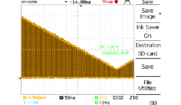
The Resulting Tone
The resulting tone of about 400 Hz that dims and comes up again in a period of abot 1 second is:
The frequency and period are not exactly 400 Hz and 1 second because there are some rounding errors. For example, 48000 * 20 = 96000, but 125 MHz divided by this number is 130.21. However, we use a counter of 130, so 1 / (8 ns * 130) = 961538.5, so the numbers don't quite match up. With a better choice for these constants, we can make this more precise.
This is a video that shows the change in voltage on an oscilloscope:
I also took a "screenshot" from the oscilloscope that shows the variation in voltage:
Reflections
From my point of view this was a good week where I learned much. It was a good choice to first make my own PWM library and from that switch to the RP2040 PWM library. I feel I have a good understanding now of the difference between dimming an LED and a speaker or buzzer, two devices that need to be controlled in a very different way. This allows me to understand how devices are controlled with pulses in general.
I also understand the capabilities of the RP2040 better now and I foresee a way to make an audio amplifier out of that device. In fact, writing this, I already succeeded to build on this design and create a simple amplifier that plays a short wave file.
Tasks
Fab Academy
- Measure the power consumption of an output device.
- Add an output device to microcontroller board that you've designed and program it to do something.
- Demonstrate workflows used in controlling an output device with the board you have designed.
- Document how you determined the power consumption of an output device.
- Document what you learned from interfacing an output device to a microcontroller.
- Document your design and fabrication process.
- Explain the programming processes you used.
- Explain any problems you have encountered and how you fixed them.
Personal
- Make a speaker from the buzzer with an amplifier.
- Play a wave file.