Safety Instructions
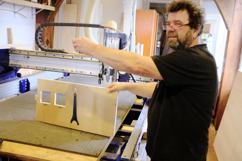
Since the use of the large CNC mill has led to deadly accidents, it is important to discuss safety instructions. Dangerous is long loose hair, loose sweaters, and straps with keys etc. The spindle rotational speed is 18000 RPM and according to Henk, long hair is not so long if it gets caught in the spindle.
Especially for this week, you can learn how good your documentation is, because Henk wants us to set up the machine and the job by ourselves to minimize the distractions. To set up the machine for a job, we will have to follow many small steps in the right order and if you forget something, you will notice that later.
An example is interchanging the milling bit, causing you to do the set up all over again. Another example is choosing the wrong milling bit in V-craft, something you will notice while milling and ruining your job.
Types of Danger and Risks
Let's list the types of danger with some background information:
Spindle Grabs Something
As we have already mentioned above, the spindle has a high rotational speed, so there is a risk that hair, long sleeves, straps gets caught in the spindle.
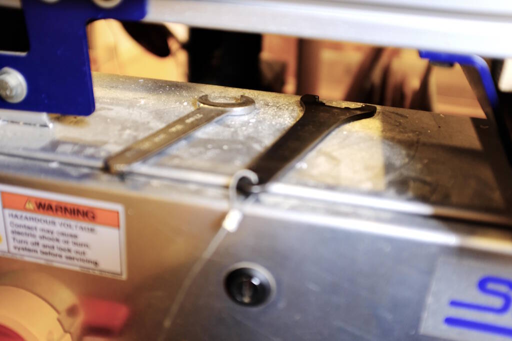
To prevent you from doing anything with the spindle, the wrenches to disengage the milling bit are connected to the key that turn on the spindle.
Distractions
There are many steps to follow, so distractions may result in forgetting important steps and also important safety steps. An example is doing an overview check for free moving parts of the machine. Henk told us about a student who tried to get more material, leaving some of the material leaning against the machine that was caught by one of the axes.
Fire by Means of Hitting Screws
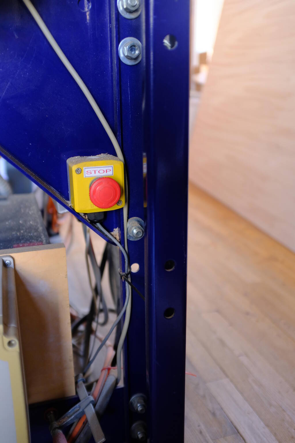
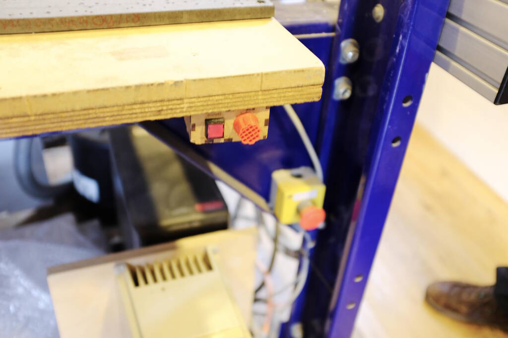
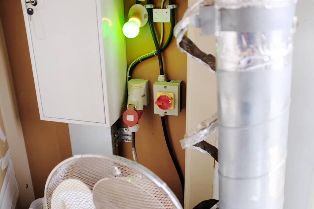
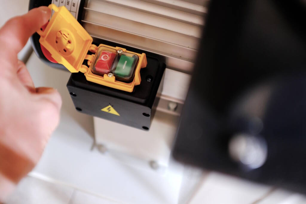
When a milling a milling bit hits a screw, the sparks will be sucked up in the bag of dust together with air. This is a good circumstance for fire, so you will have to stop the machine immediately with the emergency stop below:
The ventilation button:
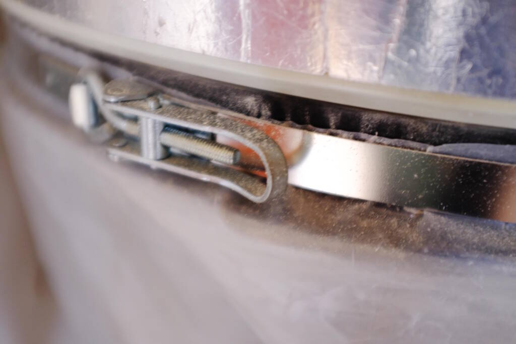
You will have to check the bag of dust immediately for melting or fire. If there is fire, disengage the bag and throw it outside through the window. If a fire starts in the bag, you won't be able to stop it. Disengage the bag with this clip:
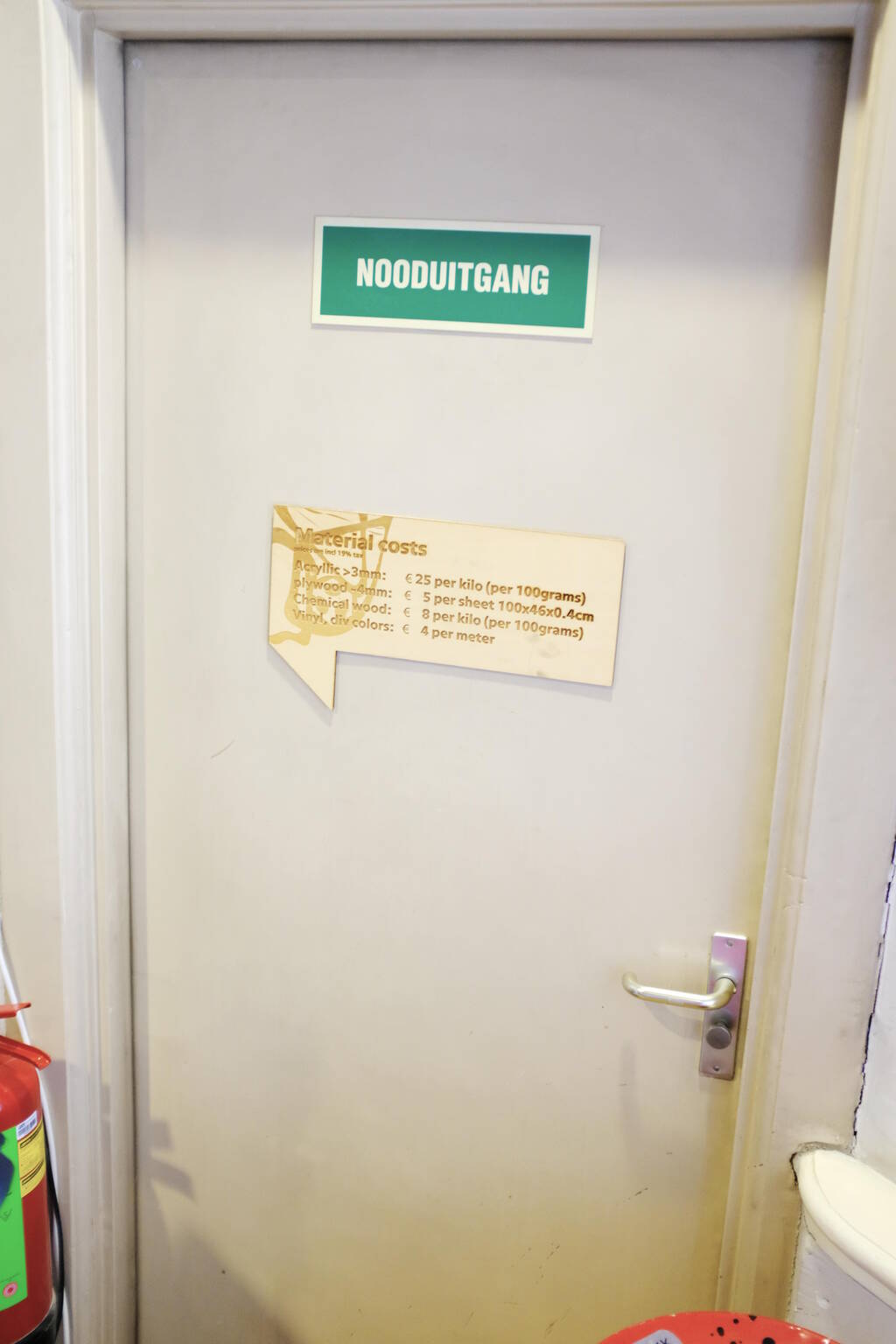
The fire exit:
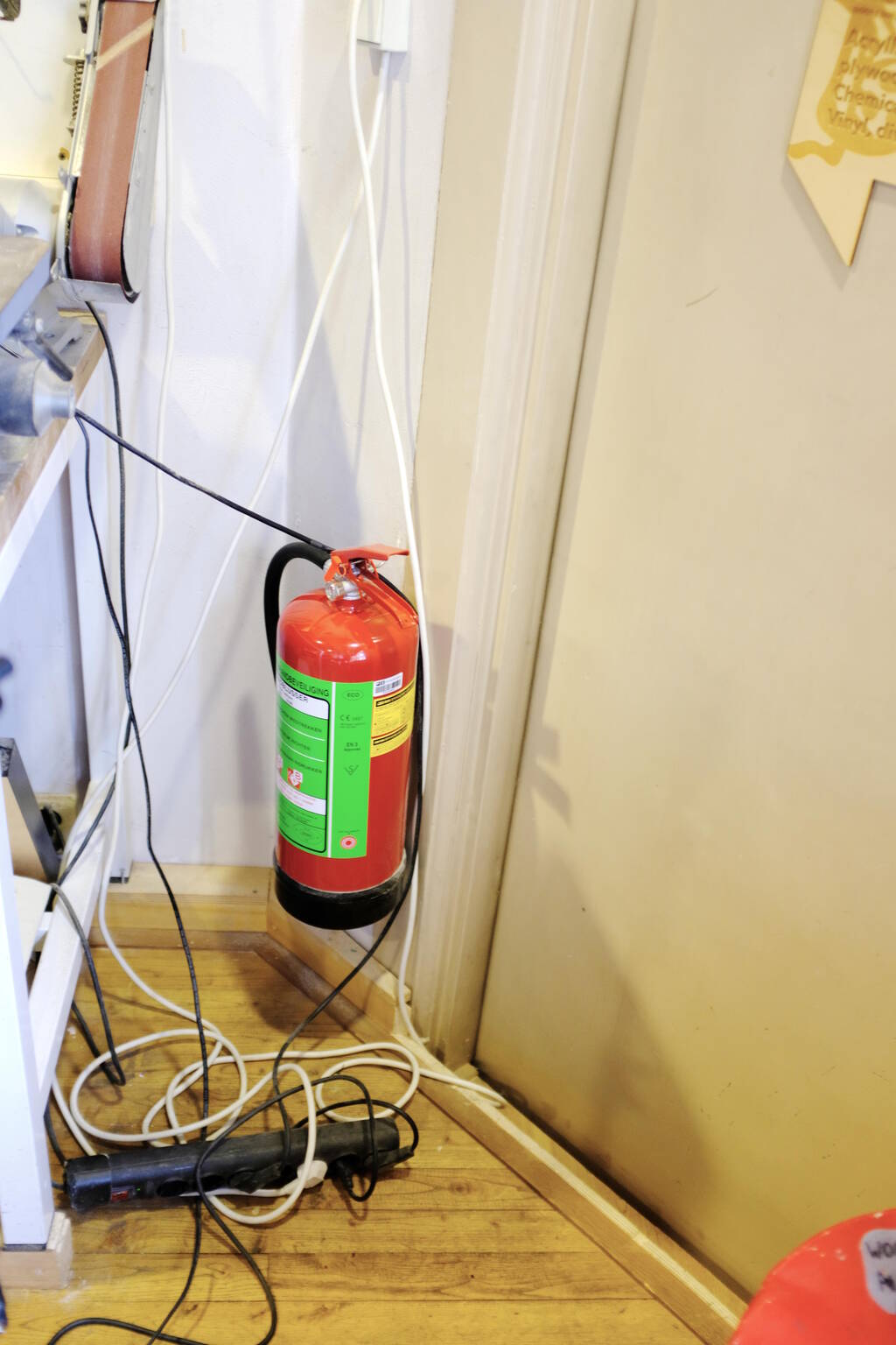
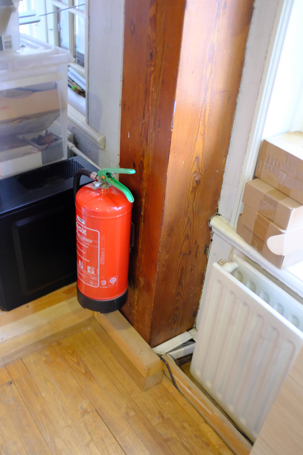
The fire extinguishers:
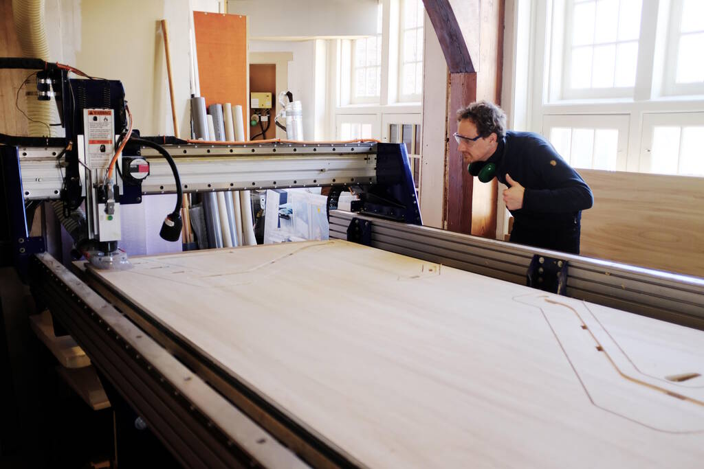
Test the ShopBot at Waag
As a group assignment, we tested our ShopBot at Waag with two materials.
Materials
We tested the parameters below on OSB (17.8 mm) and plywood (18.2 mm). Saco recommended us to have a feedrate of 90 mm/s but Samson, Michelle, and I found the noise that we got not sounding like "happy cutting" as Michelle called it. Henk agreed with us and said that 90 mm/s was too fast and recommended us to use 60 mm/s. However, this didn't help much. In the end we did not solve this issue but the sound was much better on the OSB material. We now think it had to do with the plywood that simply happened to give this kind of noise.
Runout
We measured the runout on a drill hole but that proved too difficult to measure correctly. We then measured on a tool path along the grain that had a very clean cut. On this toolpath we measured a width of 6.05 mm for a 6 mm drill bit. We can conclude that the runout is minimal on our machine.
We tested this on the plywood piece because the measurements of OSB were much more imprecise.
Alignment
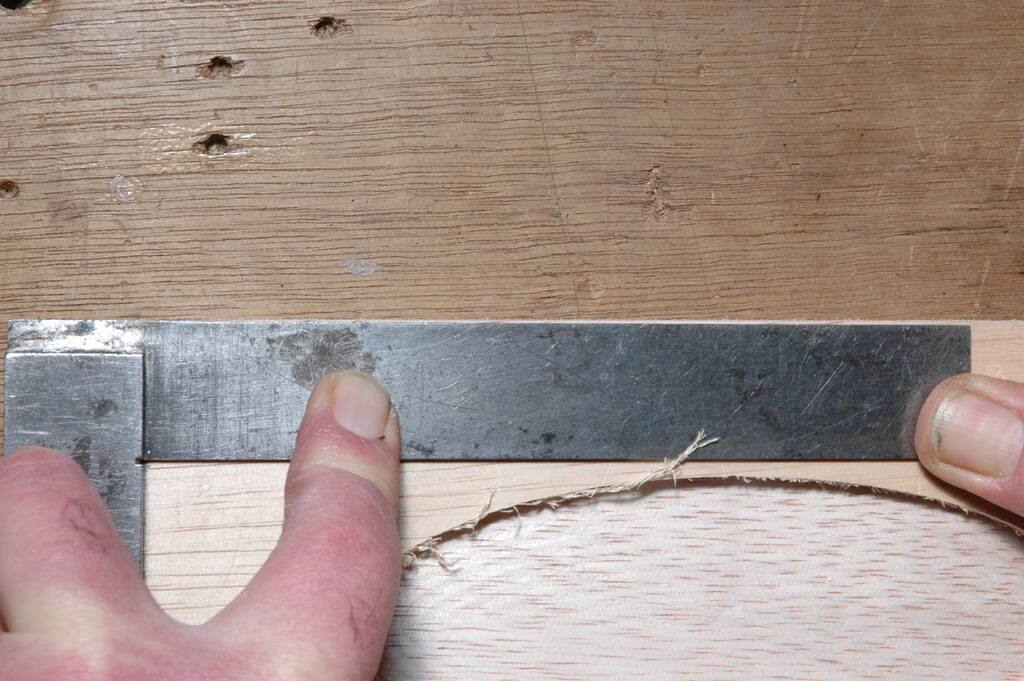
I was responsible for the alignment and we tested this on a piece that Saco milled for us. My first idea was to hold the piece against the light and these are the pictures that show you various sides:
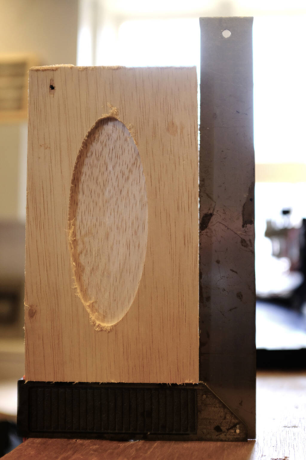
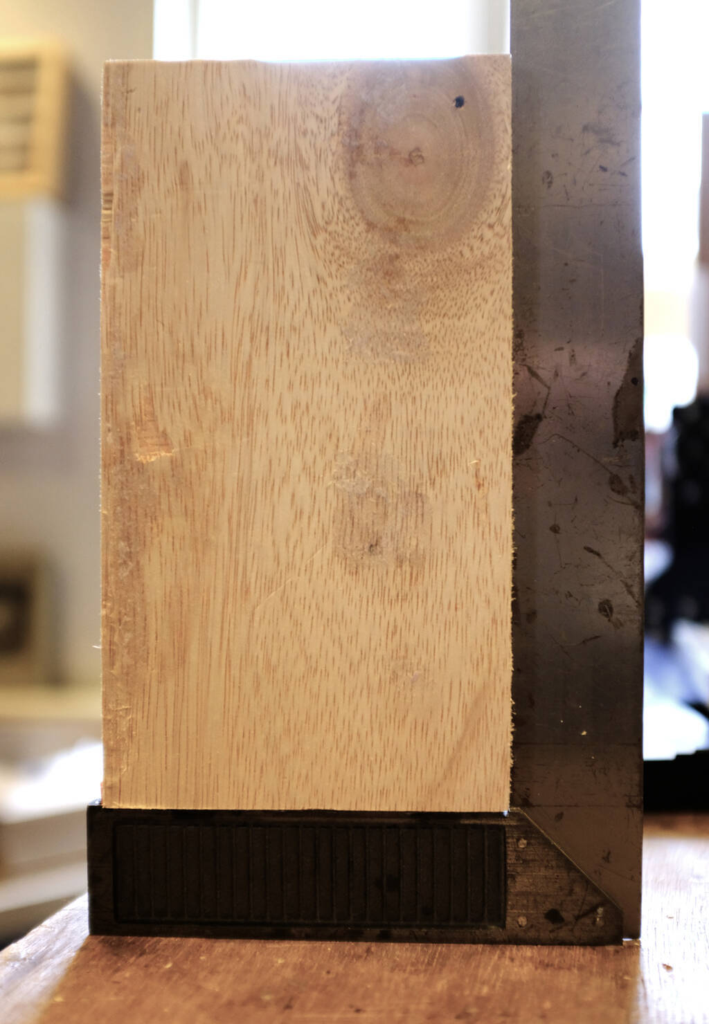
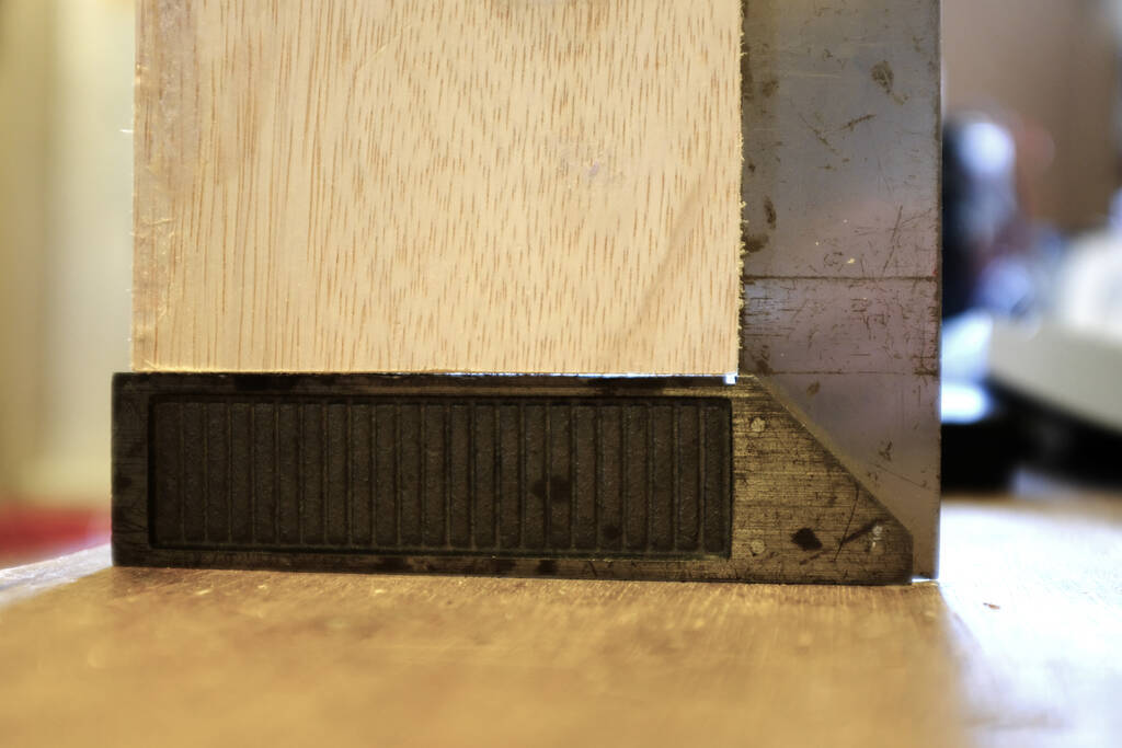
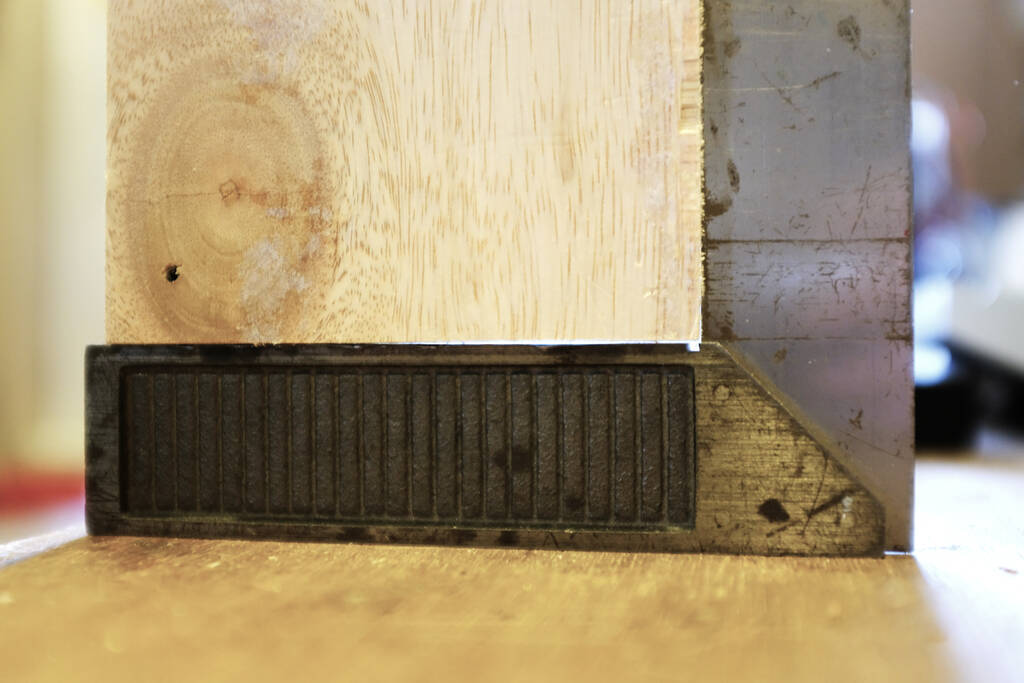
You can see that quite some light shines through, so much that Saco didn't trust the square that I used. He brought his own square that he had more faith in, but also on this square it turned out to be that the alignment was not perfect:
Fixturing
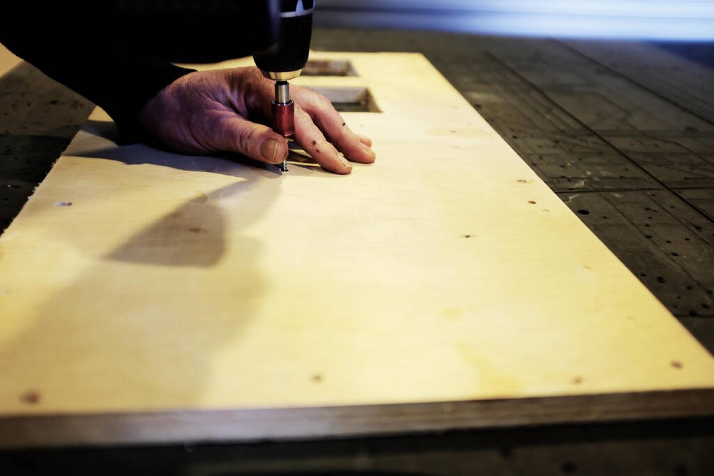
We do not have a vacuum bed, so we have to attach the material to the MDF sacrificial bed that is 15 mm thick. To prevent the milling bit to hit the screws, we are going to place drill holes manually taking care that the drill holes are not close to where the milling bit will pass. We then place the board at the correct location, zero the X and Y, move the milling bit at the location that we consider the (0, 0) for X and Y for our job, record the absolute X and Y coordinates, (taking a photo of them) and make these X and Y coordinates (0, 0). We then first run a job to drill the holes. Since there is only force applied in the Z direction, the stock piece will remain in place. After this, we screw the stock piece to the bed using the drill holes.
Feeds and speeds
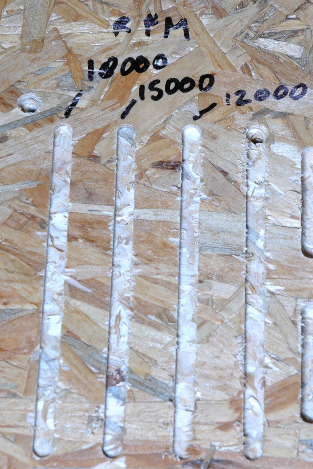
At first we tried 90 mm/s based on Saco's recommendation. This made a horrible noise and according to Henk this was too fast. Henk recommended a feed rate of 60 mm/s and we tested a feed rate of 60, 70, and 80 mm/s and a spindle speed of 18000, 15000, 12000, and 9000. We discovered that the software cannot control the spindle speed, so we measured the following speeds 18000, again 18000 when we realized that the spindle speed didn't change. We then went for 12000 by pausing the job and manually adjusting the spindle speed.
At this point we decided we were more interested in the 15000 then the 9000 version, so we did that one:
In terms of sound there was not much difference and from the pictures it is clear that the grain direction has more influence than the spindle speed.
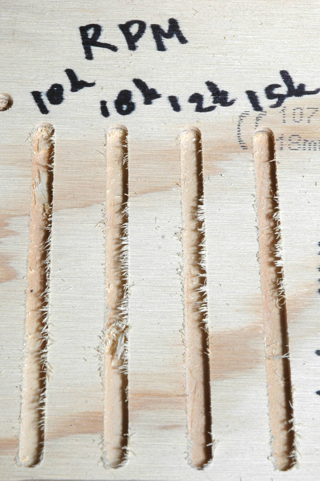
For OSB, we tested 18000, 15000, and 12000 RPM as well and again, we can conclude that the difference is small for this material:
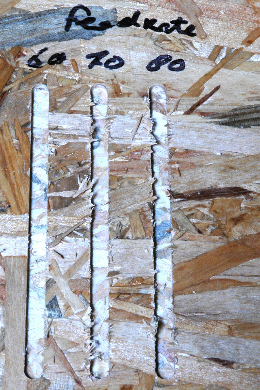
For the feedrate we tested 60, 70, and 80 and again, it is clear that the grain direction has more influence:
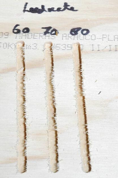
On OSB it is safe to draw the same conclusion. The 60 mm/s version looks cleaner but it has different wood chips.
Toolpaths
We experimented with T-bones and dogbones and with climb, and conventional paths. After having heard the theory behind toolpaths, we wanted to try conventional and climb paths by cutting a couple of straight lines. However, we saw in the software simulation that there was no difference in the lines after which started thinking about what this actually means.
It turns out that on a straight line, climb and conventional does not have meaning because the left side of the path (if the milling bit is moving away from you) is cut using climb, whereas the right side of the path is cut conventionally. So, in essence you are always doing both, so the choice of climb or conventional only means which side of the cut you want to have a particular finish. Based on the grain direction, this can differ as well. I think Henk's recommendation is just there to limit our choices to make sure we are not experimenting too much on our individual assignment.
So, let's make climb and strong a bit more concrete in a couple of scenarios: If you are cutting out a piece, let's say a square, you are interested in the outside cutting area of that piece, so you will cut on the outside of the path you determined. So deciding whether you want to do climb or conventional cutting depends on the quality that you get in the outside edge of that square. The spindle rotates always clockwise, so if you want climb, then the direction of the toolpath will be anti-clockwise. However, if you want conventional cutting on this outside edge of the square, you will get a clockwise path.
If you want a pocket in a piece, let's say it is a square, you will cut on the inside of the path you defined. Choosing climb here will mean that the direction of the toolpath will be clockwise, whereas choosing conventional will mean that the direction of the toolpath will be anti-clockwise.
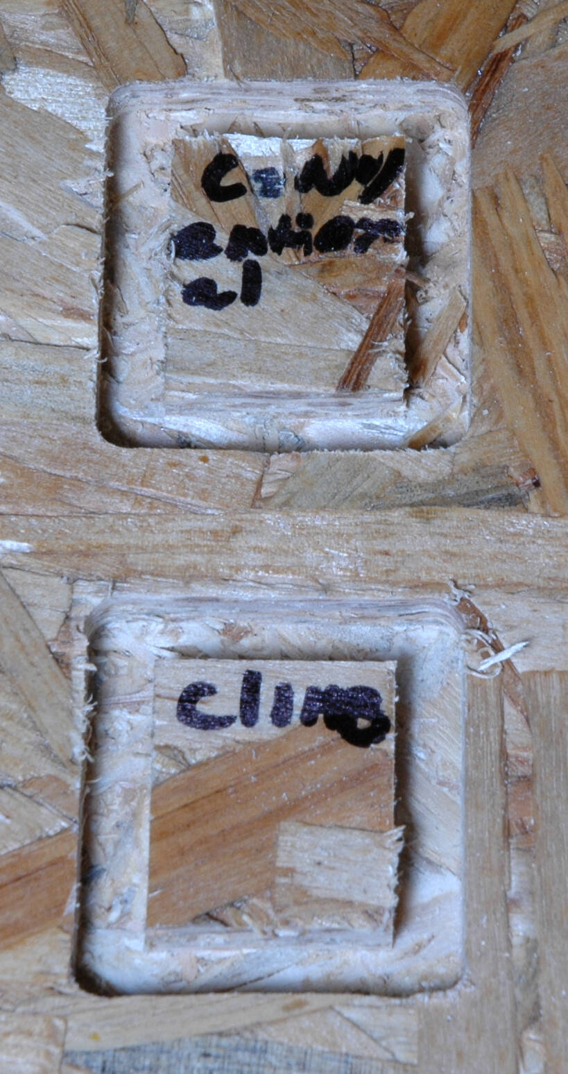
The result of the two versions on a small square:
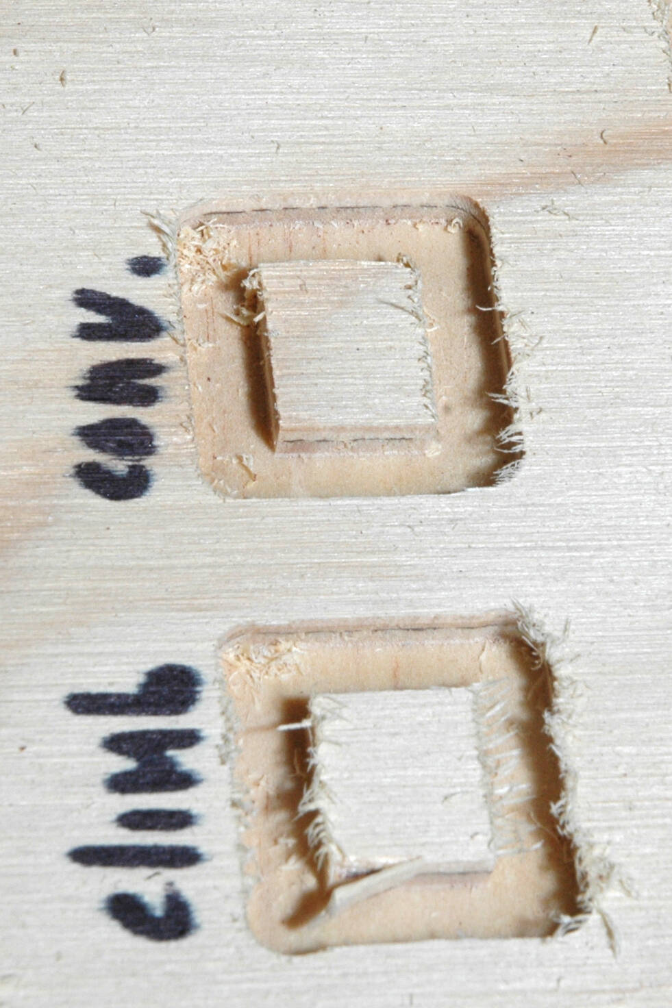
On OSB:
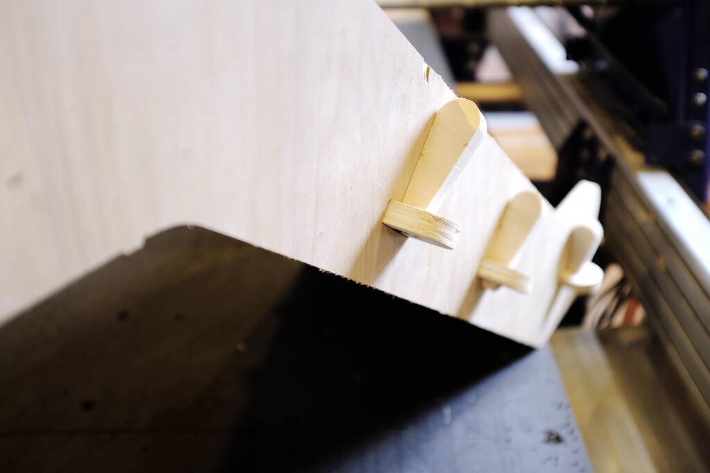
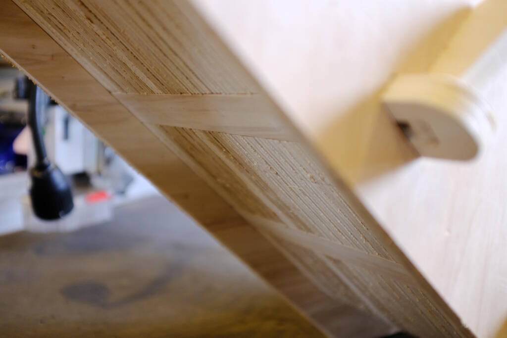
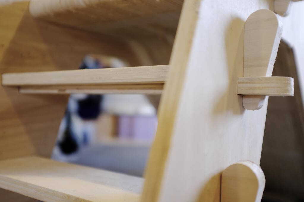
Experimenting with T-bones and dogbones with a press-fit test:
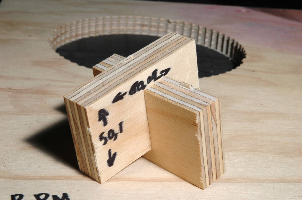
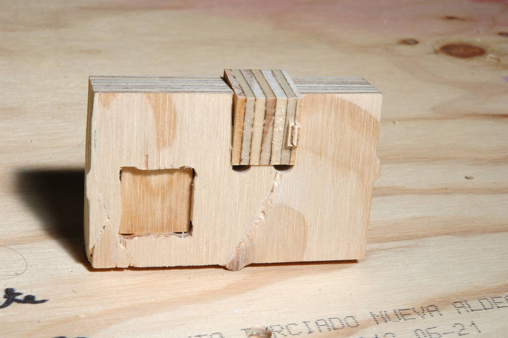
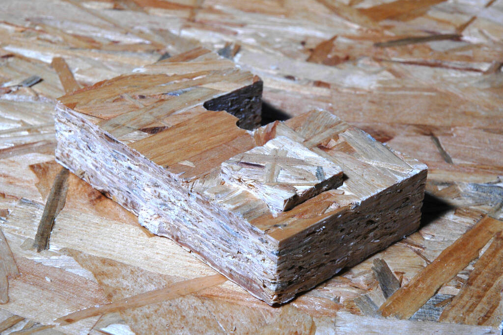
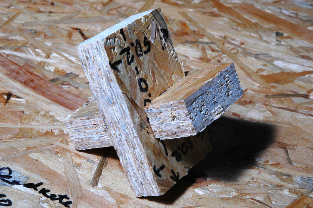
All fits rather well. OSB is more difficult to adjust because the material is so unfinished.
Design of a Children Slide (Weee)
My plan is to make a slide for my son who loves slides and calls them "weee" after the sound he makes when slides down. I first did some research if some else had already created a slide and Maro Aghazarian from Dilijan, Armenia tried to make a slide but chose another project in the end. She documented a list of safety requirements that I took good notice of. In the end because of space restrictions, I abandoned almost all safety restrictions.
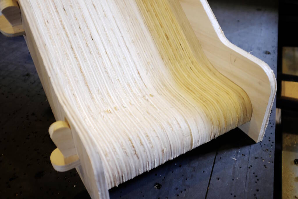
Another inspiration is a video in which a woodworker makes use of the plies of plywood as an artistic means, creating beautiful curves for a layered plywood hifi unit . I think this is a nice way to think outside the box make curves. At first I wanted to make the slide out of this, but I abandoned this idea in favor of only making the chute in this way.
Design Philosophy
Our stock material is a 2.50 by 1.22 m poplar plywood sheet of 15 mm thick. The idea is to make something big (in the order of 1m in one dimension) and use as much as material from the stock piece.
I live in a small house with a large grand piano and it would be great if the slide is not too big and fits under the grand piano. This limits the height to 68 cm. The width of the slide should be such that the slide is stable. I'm aiming for a width of more than 30 cm. Since the width is determined by the number of slices for the chute, the goal is to create as many as possible slide pieces that will form the slide in a layered way.
Since the slide is going to be small, I feel justified in abandoning the safety requirements that Maro recorded. For example, the platform to go from standing to sitting position should be at least 56 cm. I tried to design with this but this will never fit the stock piece.
I live about 30 km from Amsterdam and I try to minimize my car usage. This means that I don't want to pick up the slide with our car, but I would like to use my "Bakfiets" . This means that I should be able to disassemble and reassemble the slide.
The Design
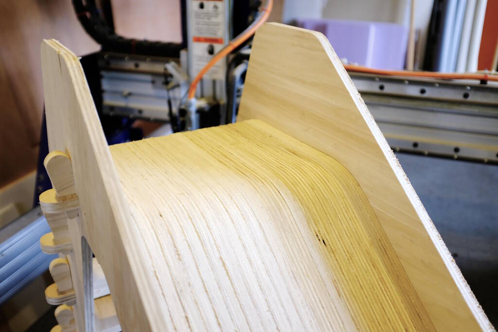
I designed the slide in FreeCAD, making use of sketches mainly and parameterize as much as possible to make sure all the pieces fit into the stock piece. The central piece that determines the rest of the dimensions is what I call the "slide-piece". It is essentially a cross section of the part that will form the slide and I will stack 22 of these to form the chute of the slide. Since the material is about 15 mm thick, this will amount to a 33 cm wide slide.

The cutouts that you see along the bottom of the slide are for horizontal cross bars on which the slide rests. The holes are for dowels to make the various slices one piece. The 22 slide pieces assembled will rest in a cutout in side panels that hold everything together:

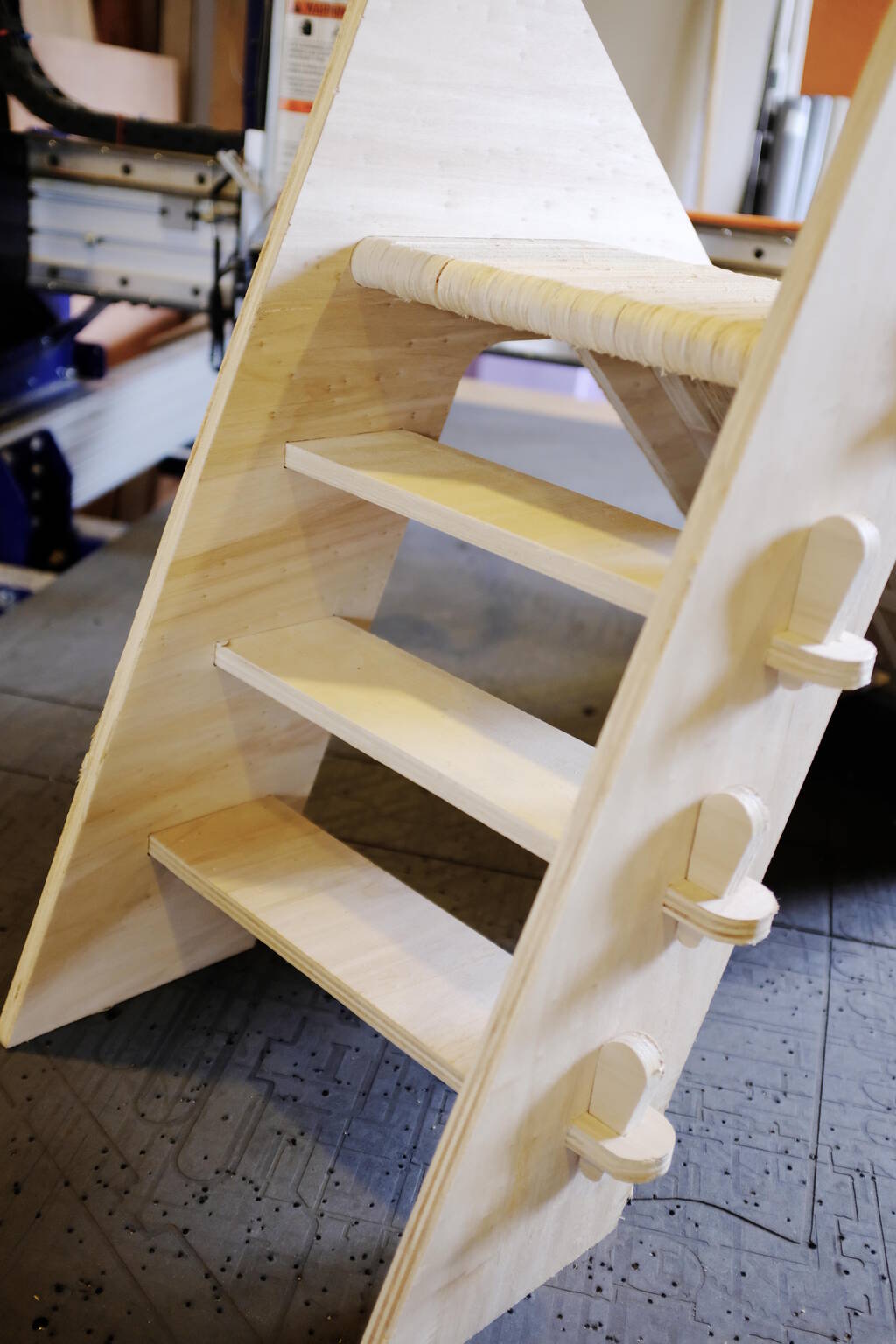
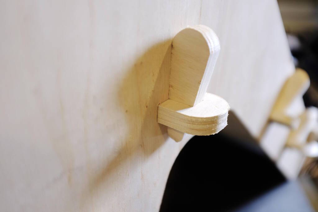
You can also recognize cutouts for three steps. Note that there are holes for the cross bars. There will be four cross bars for the slide pieces and three for each step. The crossbars will protrude the outside of the side panel and have holes on the ends to hold wedges that will clamp the side panel to the slide pieces and the steps. The crossbar:

The wedges go into the hole in the crossbar to clamp everything together:

Nesting
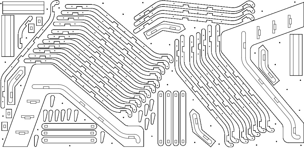
The design has evolved together with nesting everything together. I used the TechDraw workbench with a custom template with measurements 2500 mm and 1220 mm matching my stock piece. I placed each component manually on this template trying to maximize the number of slide pieces:
The final nesting that allowed me to fit 22 pieces (albeit a bit tight at some places):
Using VCarve for the Weee
Before doing the milling, we have to make use of VCarve software. Unfortunately this is proprietary software and I prefer to use FreeCAD's Path workbench but Henk told me that I need to use this software and if I understand everything about milling we can talk about using other software.
This is fair enough. I don't have to install it on my own computer and one of my goals is to understand the features of these kinds of tools to understand what is missing in open source software.
The first part of set up is to determine the job size. I measured the stock again and I measured between 15.3 mm and 15.5 mm with most of the measurements coming close to 15.4 mm. The stock is slightly larger than 2.50 m and slightly larger than 1.22 m, so the job setup I went for was 2500 by 1220 mm and a thickness of 15.4 mm.
FreeCAD's TechDraw workbench exports to SVG and DXF. I prefer SVG because I can edit it easily in Inkscape but unfortunately VCarve doesn't load SVGs. I went for the DXF format that TechDraw exports and VCarve imports, but I wouldn't be comfortable in trying to edit DXF files in Inkscape.
The import itself goes well, the DXF is overlayed on the stock that was defined in VCarve and in principle I could start milling from that. In VCarve I wanted to add holes for the screws to hold the stock piece in place, but I realized that my design was parameterized and if I want to load a new DXF with changed parameters, I loose the information of where the screws are. So, I decided to add the holes of the screws to the TechDraw nesting file to ensure that I can load a new version.
I anticipated that the export of TechDraw would not be suitable for milling, but I didn't anticipate the number of post processing it required. Most of my time was spent on getting the DXF file in shape such that I can create GCode for the mill. This involved mostly closing various vectors. Essentially, none of my vectors are closed and I have to close them manually by selecting the vectors and press "J". For simple structures such as squares, I can select all the vector elements at once, but for the slide-pieces, I can't do that and need to select each separate vector one by one and join them together.
This Join tool is very handy. If you select a vector element, for example a line segment, it tells you, you selected 1 open vector and the result is 1 open vector. If you then select a second line segment touching the original, it provides you feedback that you selected 2 open vectors and the result is 1 open vector (by means of joining). While adding each line segment to the selection, I have to carefully monitor the number of resulting open vectors keeping this to 1 at all times. If I select the final line segments that connects both ends of the selected line segments, I should see that the result is 1 closed vector. I can then join them.
If there is a gap anywhere, albeit very small, this process doesn't work, and you have to debug where you missed a line segment. Since the slide-piece is quite complex, this is a very tedious process that takes a lot of time. The following image shows that at the left that instead of 1 open vector, there are 2 open vectors, because I missed a very small vector (highlighted). I have to go through this process 22 times.
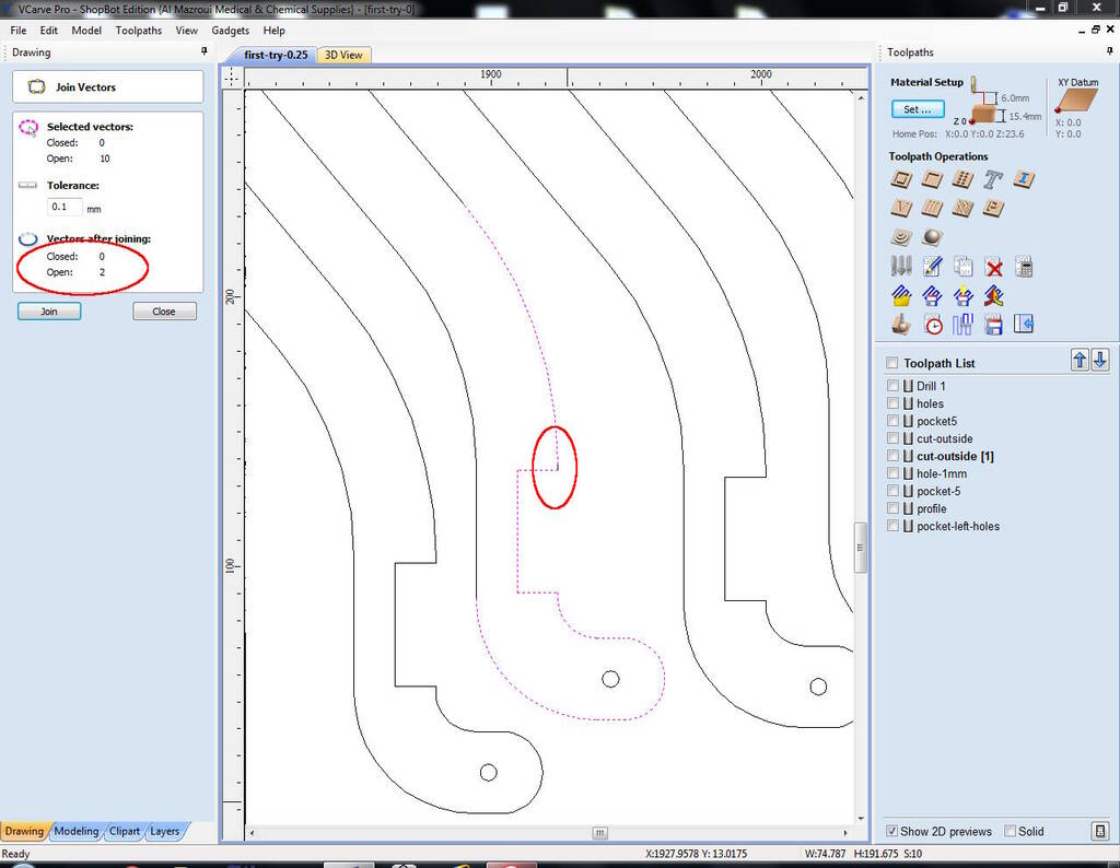
If vectors are not closed, you cannot add dog-bones and cannot create a path, so this is very important.
The Tool Paths
Since some of the lines are pretty close, I chose to use a 5 mm milling bit. We had to use a 2-flute drilling milling bit. I will use this milling bit for all the paths. I will fixate the feedrate to 60 mm/s and will use climb as cutting direction as requested by Henk. The parameters for the Mill bit selection are below this section.
I essentially make use of four toolpaths:
- Drilling 5 mm holes of depth 5 mm
- Making holes for the cross bars
- Cutouts for the slide pieces, steps, and crossbars, depth 5 mm
- Outer edges of the various pieces
For the drill toolpath I simply chose a cutting depth of 5 mm. I did not use advanced features such as peck drilling.
For the holes I used the "Pocket" tool path with a cutting depth of 15.4 mm, the thickness of my material. For the cutouts I used the same settings except for the cutting depth which I set to 5 mm. For clearing the pocket I used offset and "climb" for direction.
For the outer edges I used the Profile tool adding tabs of 6 mm wide and 4 mm high. It should cut on the outside of the line, again with cutting direction climb.
Choose a drill bit in VCarve
In VCarve, we have to select a drill bit. Michelle defined the FabAcademy 5 mm drill bit that I used as well. These are the parameters:
| Parameter | Value |
|---|---|
| Tool Type | End mill |
| Diameter | 6 mm |
| Pass Depth | 4 mm |
| Stepover | 60 % |
| Spindle Speed | 18000 |
| Feed Rate | 60 mm/s |
| Plunge Rate | 20 mm/s |
Checklists for Milling
I decided to make a couple of checklists for milling. Since many parameters depend on each other, it is difficult to make a definite checklist, but I will try my best.y
Preparation
- Clean up the whole space such that you have a good overview.
- Flatten the parts where screws were used in the previous job by sanding the bed.
- Measure the thickness and other dimensions of the stock material.
- Place the material onto the bed but such that you can still zero the Z axis with the plate.
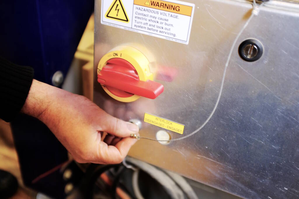
- Turn on the power switch in the back such that the green light is on.
- Turn on the computer.
- Turn on the CNC Mill (but not the spindle).
- Open the ShopBot program and press 'K' to move the milling head towards you, see below details on how to move the milling head.
- Measure the milling bit and the collet.
- Insert or check the milling bit, see below.
- Zero the Z axis, see below.
- Zero the X and Y, see below.
- Place the stock material at the location you want.
- Move the milling bit to the location where you want your Job X and Y zero coordinates.
- Take a photo of the absolute coordinates.
- Make the current absolute coordinates the Job X and Y zero coordinates.
- Turn on the dust collection.
- Turn on the spindle.
- Check whether the machine can move freely.
- Load the tool path with the drilling holes and run it.
- Screw the stock material to the bed using the drill holes.
The green light:
Moving the Milling Head
The long side of the machine is the X axis, the short side of the machine the Y axis. The computer terminal of the machine is positioned such that you are looking into the Y direction:
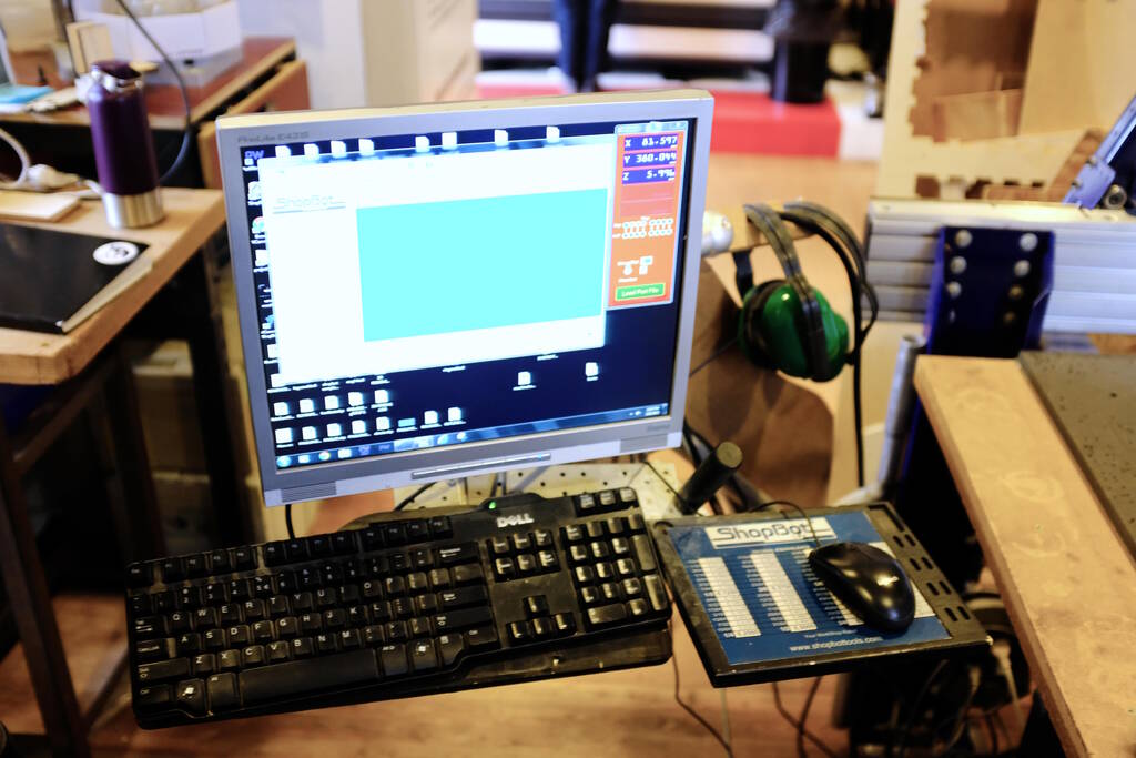
This means that the arrows on the keyboard have a "natural" meaning when moving the milling head. The left arrow means that the milling head comes towards you along the X axis and the right arrow moving away from you. The up arrow means that milling head moves along the Y axis in the direction of the arrow.
Raising the milling head can be done with Page Up and Page Down. There is a bit of a delay in moving the milling head, so moving has to be done with care.
To move the milling head, open the ShopBot program on the computer terminal and press "K" for the keypad.
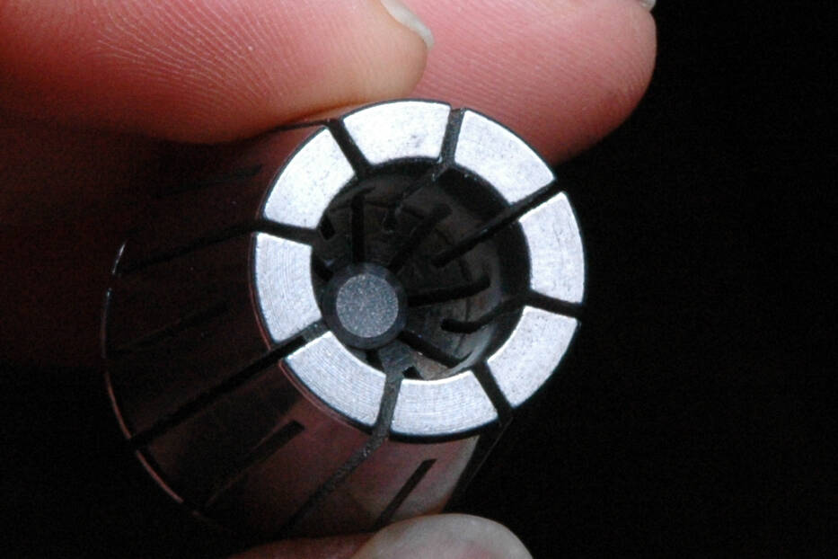
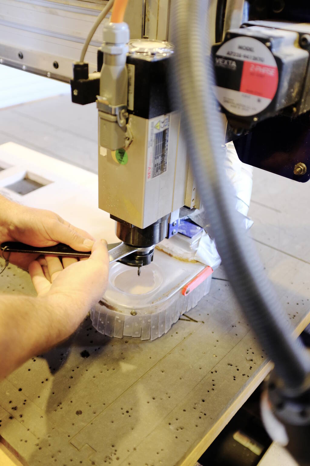
Insert a Milling Bit
It is best to measure the diameter of the milling bit and find the right collet (the diameter is on it):
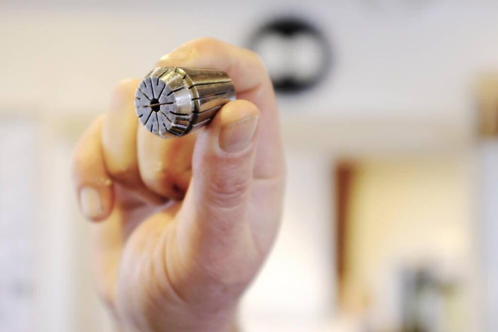
To double check, the collet is right for the milling bit if the bit is snug in the collet and little power is needed on the collet to clamp the milling bit.
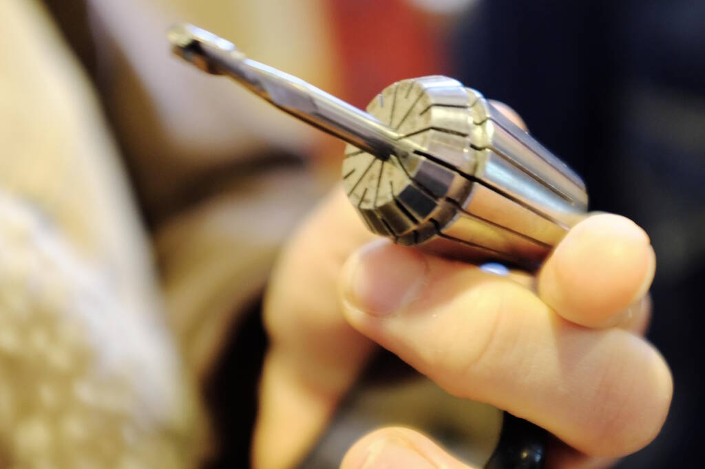
The milling bit should not protrude too much or too little. You can see inside where the top of the milling bit has to be flush with the round edge inside the collet. Protruding too much:
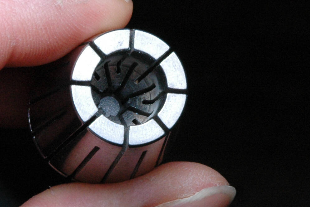
The mill bit entered too deeply:
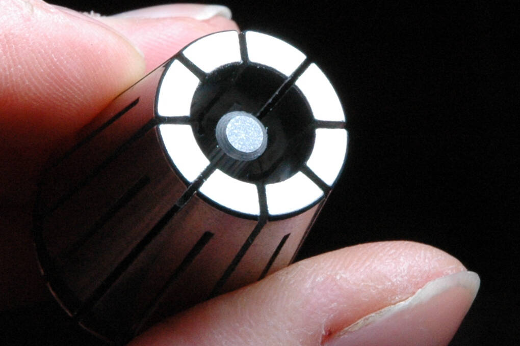
Correct:
The collet has to click in place in the collet nut.
Screwing in the drill bit has to be done with care and you have to make sure that the drill bit doesn't move up or down. So, you have to hold the milling bit in place while screwing the collet nut onto the spindle.
The collet nut has to be tightened with care. It has to turn easily without much force and you don't have to tighten the collet nut supertight. Tight is enough.
Adjusting the dust collection skirt:
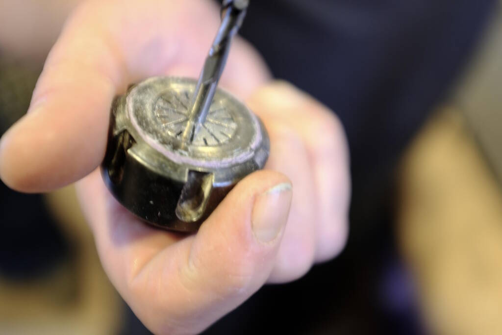
Zero the Z-axis
Michelle recommended to zero the Z axis in the middle of the Y axis about 20 to 30 cm away from short side of the bed. So, you move the milling head there, touch the drilling bit to make sure there is a signal on "COMM 1" in the ShopBot program.
Then you can carefully place the metal plate right under the drilling bit and press the button to zero the Z axis. You can raise the milling head when done.
Zero the X and Y Axis
This can simply be done by pressing the Zero X and Y button. After this, you can move the milling head to the location you want. The coordinates that you can see in the program are now absolute coordinates. It is a good idea to take a picture of these coordinates! If you need to reset the machine or the computer, you can find these coordinates again.
You have the option to make this the job zero coordinates. From this moment on, the coordinates that you see are not absolute coordinates any longer, but the coordinates relative to (0, 0) that you determined it to be. To do this choose Zero ➜ Zero Axes (X & Y) in the menu.
Create a Tool Path in VCarve
We assume that the paths have been defined correctly and all the vectors are closed ones. We also assume that the stock material settings are entered correctly. See the section on VCarve for more information.
- At the right side we can open the tool paths panel and it is wise to pin the panel immediately.
- We choose either profile, pocket, or drilling.
- Enter the settings with care and first the cutting depth.
- Select a drill bit, specifying several parameters, see below.
- Select conventional or climb.
- Add tabs for the profiles, I used 6 mm ones with a height of 4 mm.
- Select the geometries to cut and press calculate.
- Select the toolpaths for a job on the CNC mill and save them to a ShopBot file. It is wise to check whether all the right toolpaths were selected.
Running a Job on the CNC Mill
We assume that the board is attached properly, the Z axis has been zeroed correctly, and the machine has the right X and Y coordinates.
- Check or realize for yourself whether the spindle holds the right mill bit.
- Load the file with the toolpaths. Make sure it is the right file.
- Turn on the dust collection.
- Turn on the spindle.
- Check whether the machine can move freely.
- Press start and then OK.
- Hold your hand above the space bar to be able to pause the job immediately.
- Listen for weird noises.
- Stay there until the job finishes.
After the job has completed, the machine will return to origin. You can turn off the spindle and the dust collection.
Milling the Weee
Explaining Henk my design, he told me it would take all day to mill this. I didn't anticipate this, I thought this was doable in the 4/5 hours I had available for this and estimated that it would took 3 hours for cutting. Henk laughed and told me that I didn't have experience so my estimation was based on nothing. I guess he's right. So, as a fallback, I could focus on cutting only a couple of slide pieces just to show the main concept. So, I was pretty flexible with this design.
Tolerances and Clearances
After the preparation, I realized that my file needed lots of processing in VCarve, mostly joining the vectors together. I created a couple of small test pieces that mimick the techniques that I use. This helped me to find the right tolerances. The tolerances were defined in the FreeCAD file, so if I find a different setting, I should reload my DXF exported from FreeCAD.
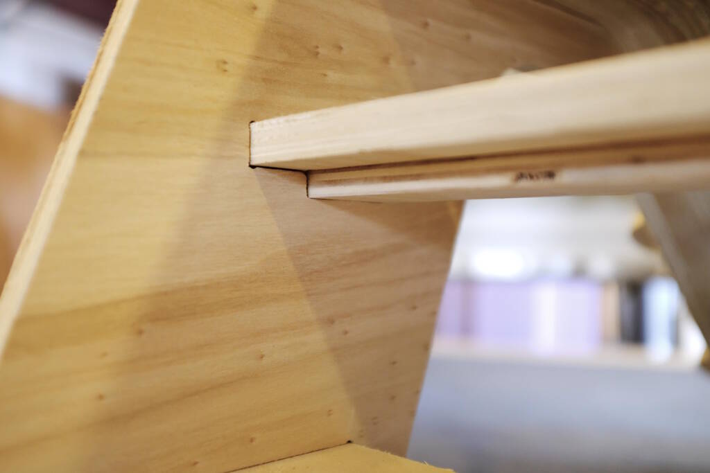
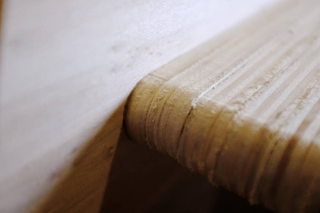
The test piece for tolerances for cutout of the curved chute:

The test piece for fitting this test slide piece into the side panel:

The test piece for the cross bar:

I also milled a wedge to try to fit it into the hole of the cross bar.
I started with a clearance of 0.25 mm but it was clear that nothing would fit. I settled for a clearance of 1 mm and redid the test piece for the side panel. It turned out that the slide piece fitted well, a bit loose. I would have preferred to test a bit more, but I was running out of time. My design is not meant to be press-fit, the wedge should hold everything together.
Disaster Management
With these parameters settled, I continued milling, taking it piece by piece because I need so much processing in VCarve. All went fine until disaster struck and I heard a noise getting louder and louder. I now know how I react in panick mode and it is not pretty. I basically completely froze because of my confusion. I had been milling for a couple of hours already and when I heard this noise getting louder I focused immediately on the milling head. However, I was confused because it was doing exactly what it had been doing all of the time and it looked as if it was doing the right thing.
Because of my ear protection I couldn't hear well where the noise was coming from. I froze because of the disconnect of the loud noise and the milling doing exactly what it should do. In the mean time the noise was getting louder and louder and Henk came rushing in. This made me decide to simply hit the stop button and Henk realized that the dust collection was at fault so he turned that off. From the closet where dust collection was, came dust swirling into the room. Henk told us that cutting was over, most likely for the rest of the week and that he didn't have time to debug this because of his lecture on debugging.
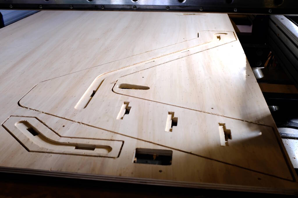
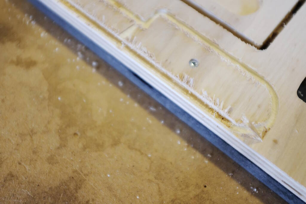
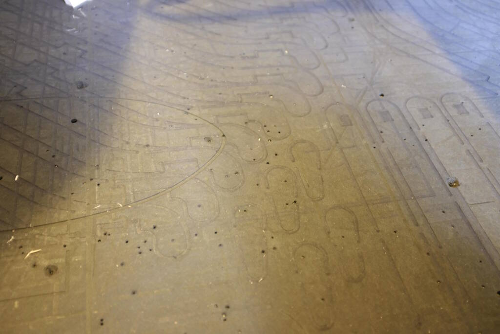
So, after this happened, I simply got back to work, joining vectors and vectors and vectors. A picture of the unfinished work covered in crisp sunlight that awaits a positive outcome of this milling job:
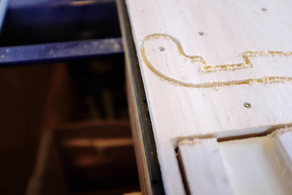
Recording the position of where the machine ended:

Reflections
Apart from the faulty dust collection, milling went well. I think the design of the slide is nice, but I didn't realize how much work it was and how much milling time it would take. I seem to have a habit of coming up with seemingly simple designs that turn out to be quite complex.
Part of the problem is that we don't really know any of the tools we are working with. I now understand FreeCAD a bit better, but I didn't realize that the TechDraw DXF export would have open vectors.
VCarve is a completely new tool with so many options that it is easy to make a simple mistake that can ruin the whole job. Then the machine itself is also new and the software to operate it.
Then all this is compressed into one short week which does not give you any chance to figure out better solutions. For example, it would help much if I had the time to figure out whether there is a better way to export the cutting lines from FreeCAD.
I think that the checklists help a lot of diminishing the chance of mistakes and I think they are not definite as well. There are always small checks you can add, I can imagine.
Anyway, too bad that I couldn't finish the project. Let's hope it gets fixed soon. In any case, my conclusion is that I want a mill myself!
Milling the Weee Continued
During last week's review Samson was chosen to speak in which he had to confess that he didn't finish the milling because of the problems with the dust collection. Thanks for blaming me :-) Samson.
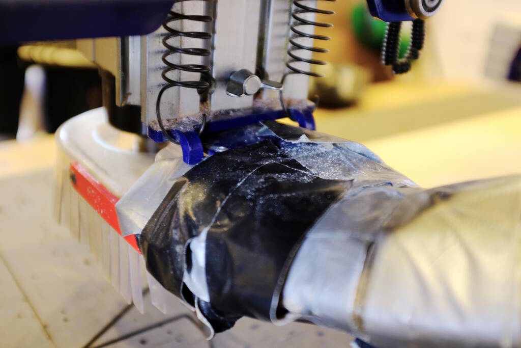
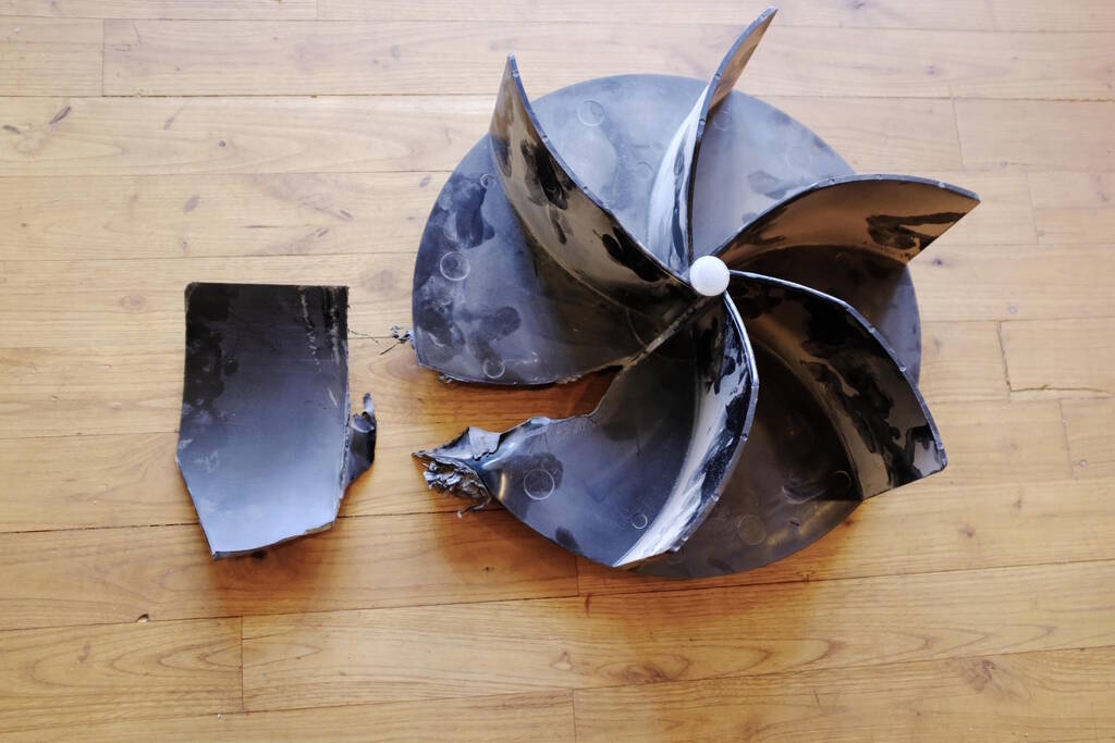
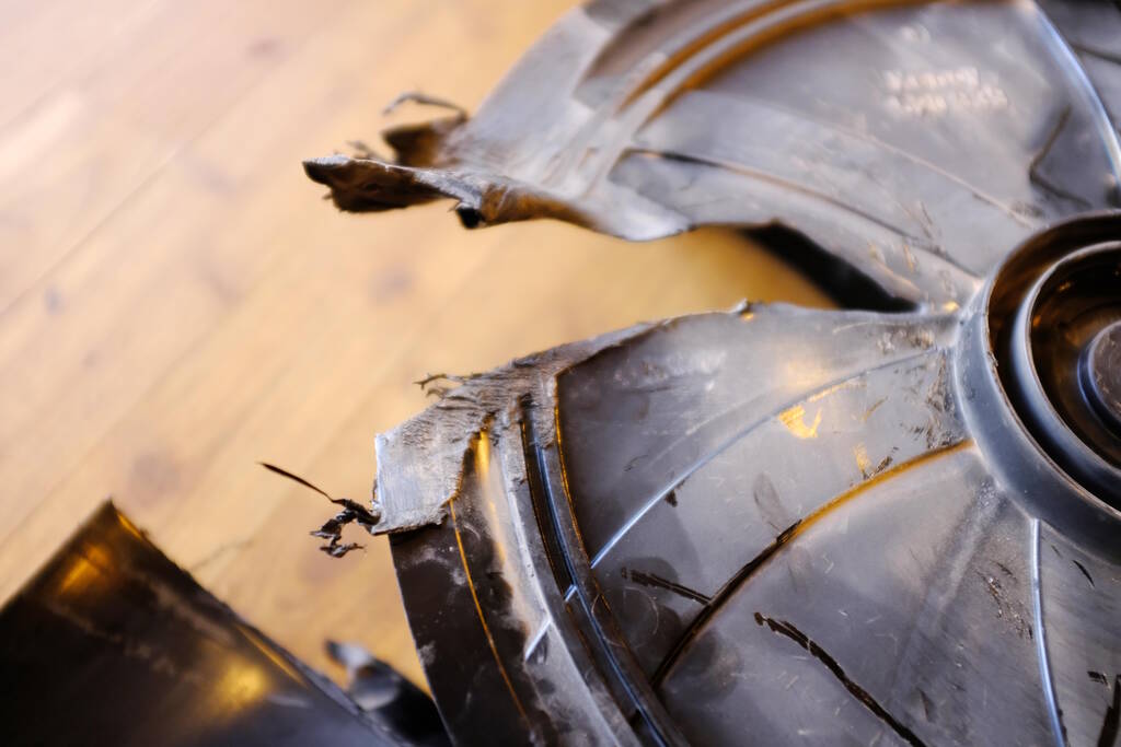
The Dust Collector Issue
This was the issue:
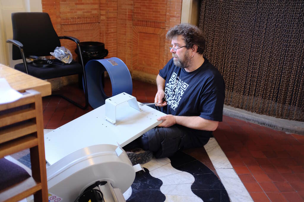
This was Henk, assembling a new one while we were having the review session with Neil:
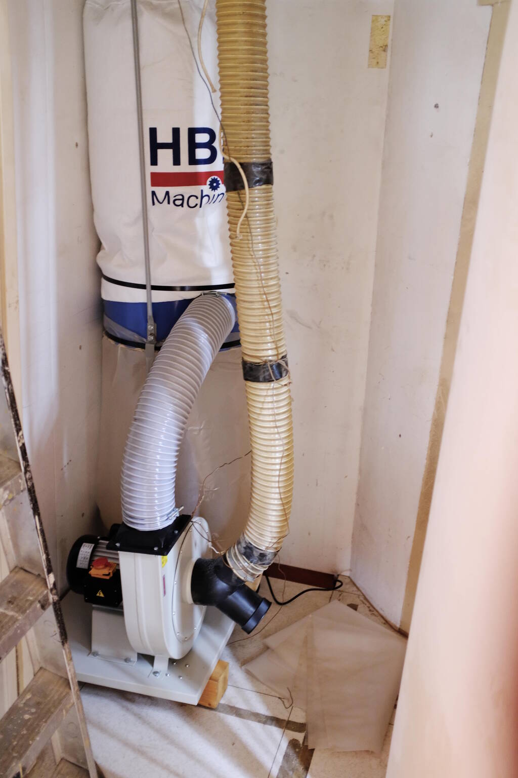
The finished new dust collector:

Changes for Operating the Dust Collector
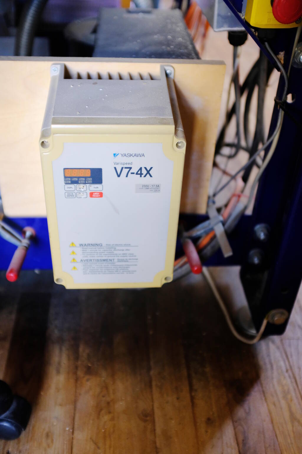
The new dust collector is in the same location:
Using 3-phase power is not necessary anymore (with the green light) and you can simply turn it on with these two buttons:
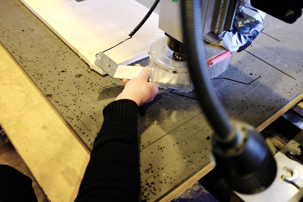
Continuing Milling
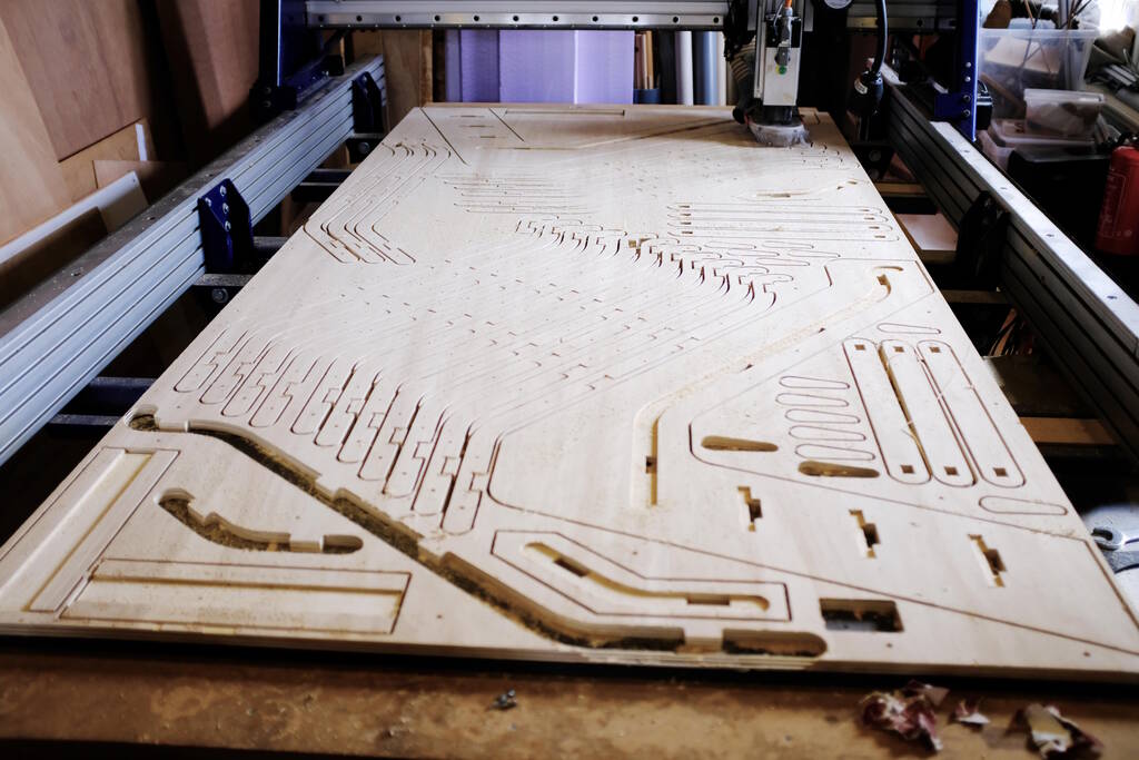
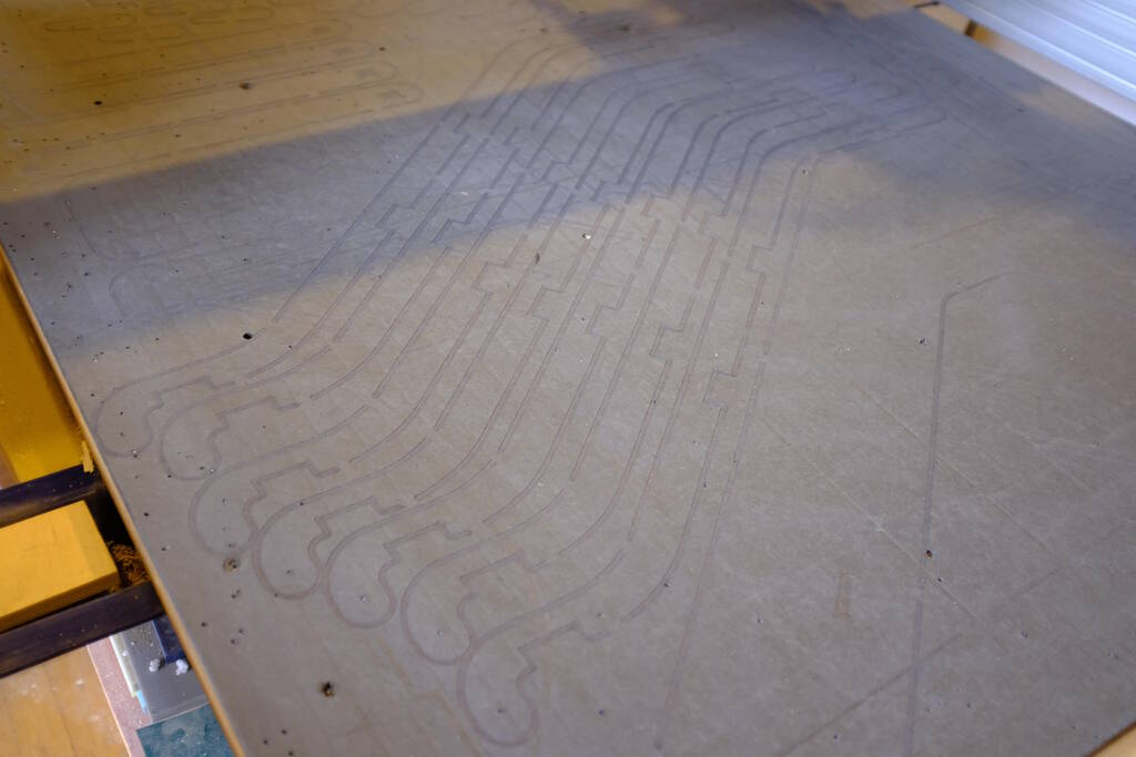
On Friday I continued my milling job:
Since my job origin was machine origin, it was easy to find the right location. I unscrewed a couple screws and slid the Z zeroing plate underneath the board where a hole was milled. After finding the X and Y origin, I could simply restart the job.
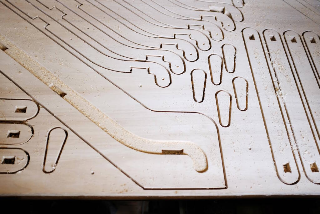
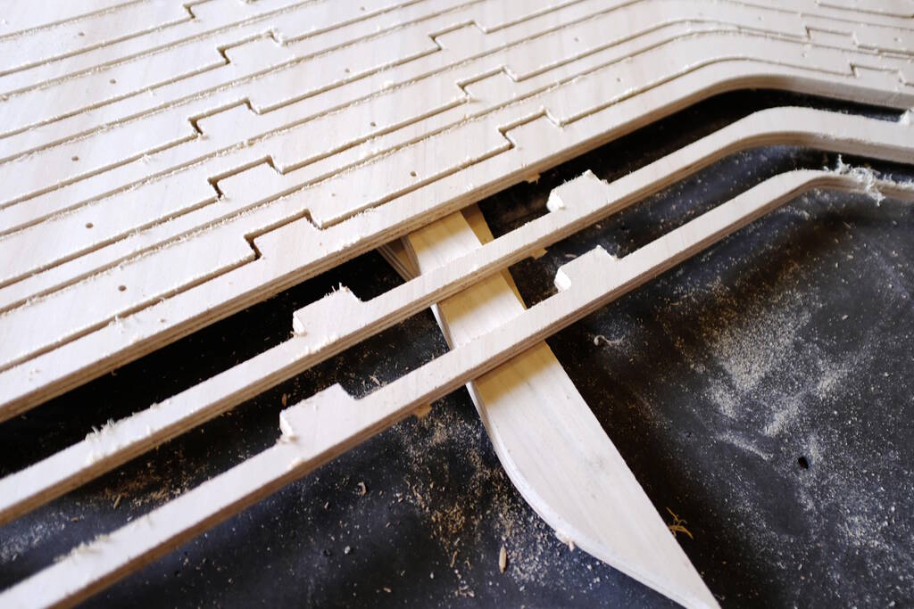
As you could see above from the nesting image, it was very tight but luckily my measruments and calculations were correct. You can see here how tight it was:
Even tighter:
On the other side:
Yet another side:
This took forever... (well actually 2 hours, less than I expected, still very, very boring...):
Some more pictures:
Afterwards Henk was not really happy with the traces that are left in the bed:
However, I simply zeroed on the bed, so in principle the mill should not go into the bed. Apparently the bed is not level anymore.
Getting so many pieces out was a tedious job:
Assembling the Weee
While the job was moving forward, I checked a couple of pieces for
dimensions and found that my cross bar was too wide. I looked in the CAD
file and noticed that the parameter was wrong:
width_clamping_bar_cutout - clearance_clamping_bar
should have been:
width_clamping_bar_cutout - 2 * clearance_clamping_bar
. I corrected
this for four of the seven pieces in VCarve and after milling I used one of
the correct ones as a template to sand away 0.5 mm on the thicker ones.
However, this was the only mistake I made and after a bit of sanding all parts fitted perfectly. The end-result is exactly what I had in mind:
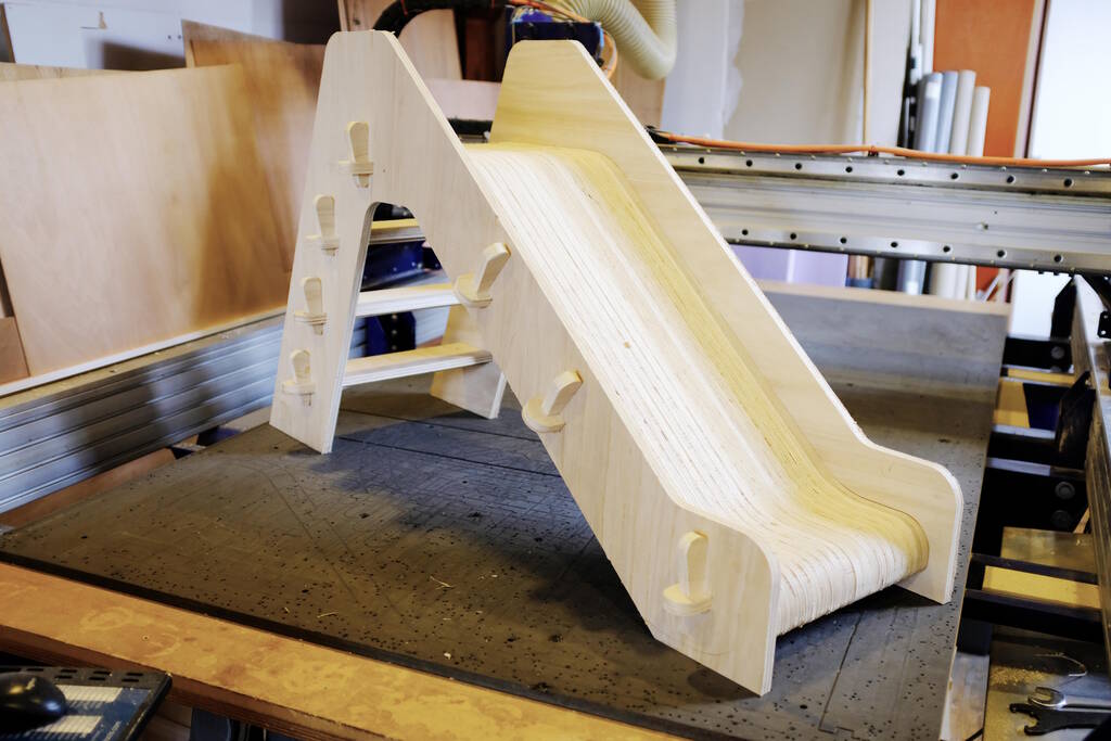
Some details:
The steps:
The cross bars with wedges that hold everything together:
They fit perfectly in the slot that each slide piece has:
The same is true for the steps. Note that the steps and the two outer slide pieces fit perfectly in a cutout:
The crossbar below a step with a wedge:
It took some time and a dust collector, but I'm happy with the end-result!
Tasks
Fab Academy
- Complete the lab's safety training.
- Test runout, alignment, fixturing, speeds, feeds, materials and toolpaths for your machine.
- Make (design, mill, assemble) something big.
- Demonstrate 2D design development.
- Describe workflows for CNC production.
- Document how the object was designed.
- Document how the CAM toolpath was set up.
Personal
- Bring the Weee back home in the bakfiets.
- Sand the Weee.
- Stain the Weee.
- Fix the (small) issues in the design.
- Make an assembly of all the components.
- Make a proper repository and release it.