Test the Lab 3D Printers
As group assignment, we are going to test the design rules of the 3D printers in the lab. Michelle, Samson, and I all own a 3D printer so we all have already experience with 3D printing. I have never been able to compare my cheap Prusa clone with another printer, so my goal is to compare my printer to the lab printers as well.
The 3D Printers
We have the following 3D printers in our lab. The first four printers are the ones we have in the lab, the last one is the printer that I own. The Ender is actually Michelle's.
| Printer name | Nozzle size (mm) | Filament (mm) | Enclosed | Note |
|---|---|---|---|---|
| Prusa i3 MK3S+ | 0.4 | 1.75 | yes | The go-to printer in the lab |
| Ultimaker 2+ | 0.4 | 2.85 | no | Annoying bed leveling |
| Creality Ender 3 | 0.4 | 1.75 | yes | Decent printer, no bed levelling |
| SainSmart INFI 20 | 0.4 | 1.75 | no | Belt printer |
| Zonestart P802QS | 0.4 | 1.75 | no | Prusa clone, steel frame |
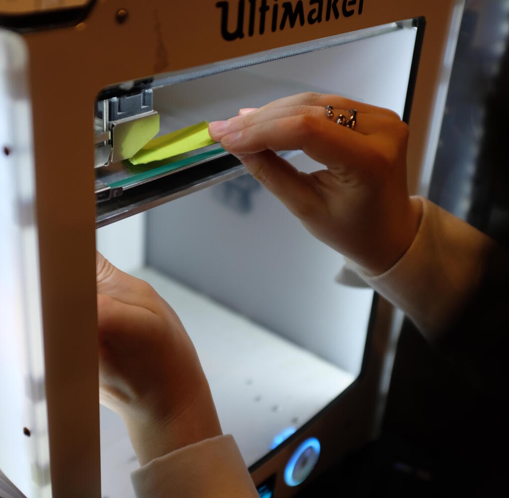
Michelle gave Samson and me a brief introduction to the pecularities of each printer in the lab and how we clean the beds at Waag. She showed us how to level the bed of the Ultimaker by following a "bed-leveling tour" from the printer in which you are to carry out several steps prompted by the display on the printer. You are aiming to find the same resistance of the three points that the printer asks you to measure:
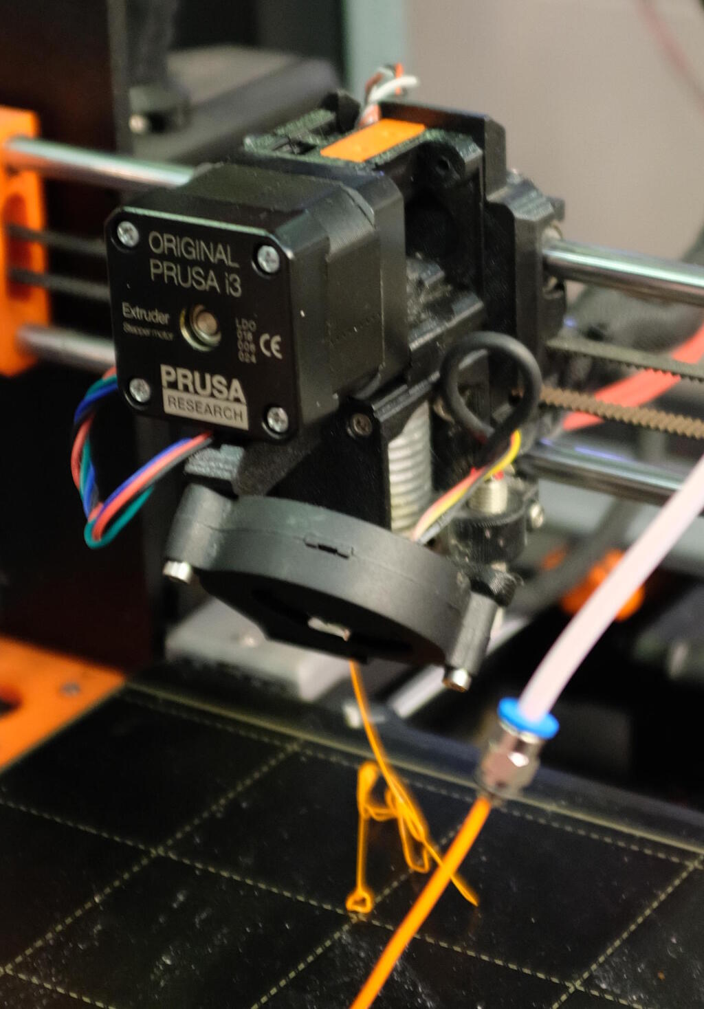
At some point the Prusa was clogged and Michelle also showed us how to unclog it. First remove the filament and then unscrew two screws on the print head, on the left side and on the back at the right.
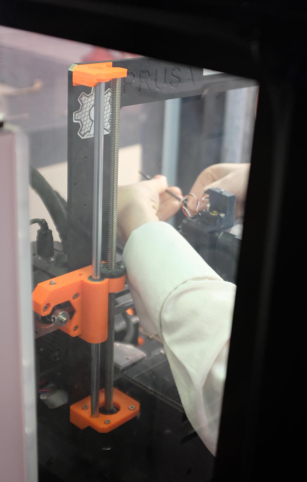
The printer opened where we could see the clog inside the white tube:
Test setup
Henk gave us the assignment to test the design rules for the 3D printers using standard settings and change only one thing at a time. He gave us an introduction to the new features in the upcoming Prusa Slicer release and recommended us to use the Prusa Slicer as the future of Cura is unknown. However, after delibiration we decided to use Cura as a slicer because the Prusa Slicer didn't have a profile for the Ultimaker 2+ and for the belt printer there is a modified version of Cura, so choosing the same slicer gives us more ground to compare.
Since PLA does not need a fixed enclosure with ventilation, this is the filament that we can use for all printers. Unfortunately, the Ultimaker uses a different filament size, so we could not use the exact same filament here. For the Ultimaker we used black PLA that was available in the lab and for the other printers we used Prusa filament. Since we cannot use the same filament, our assumption is that the filament is not a factor in performance differences.
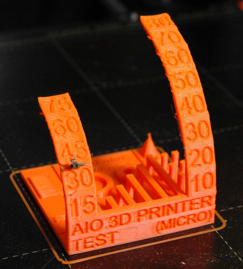
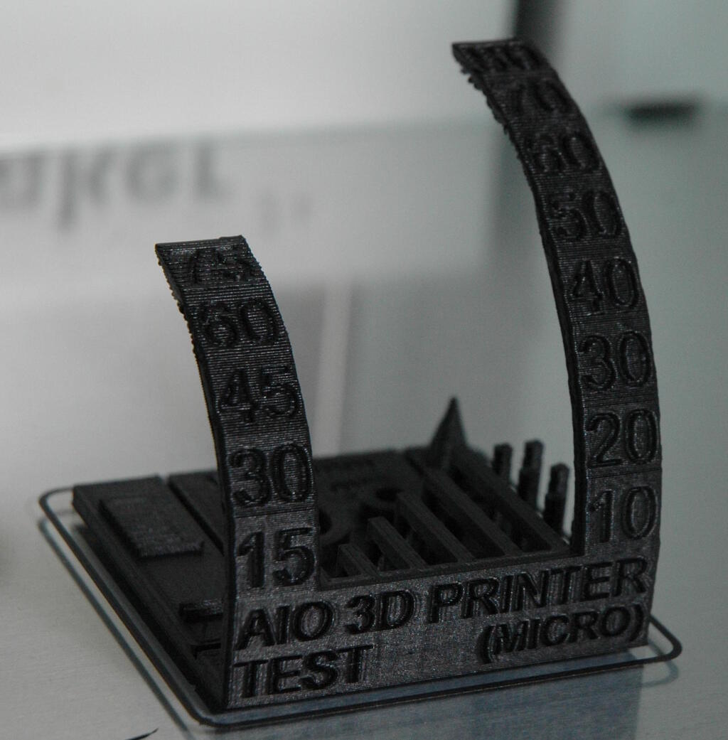
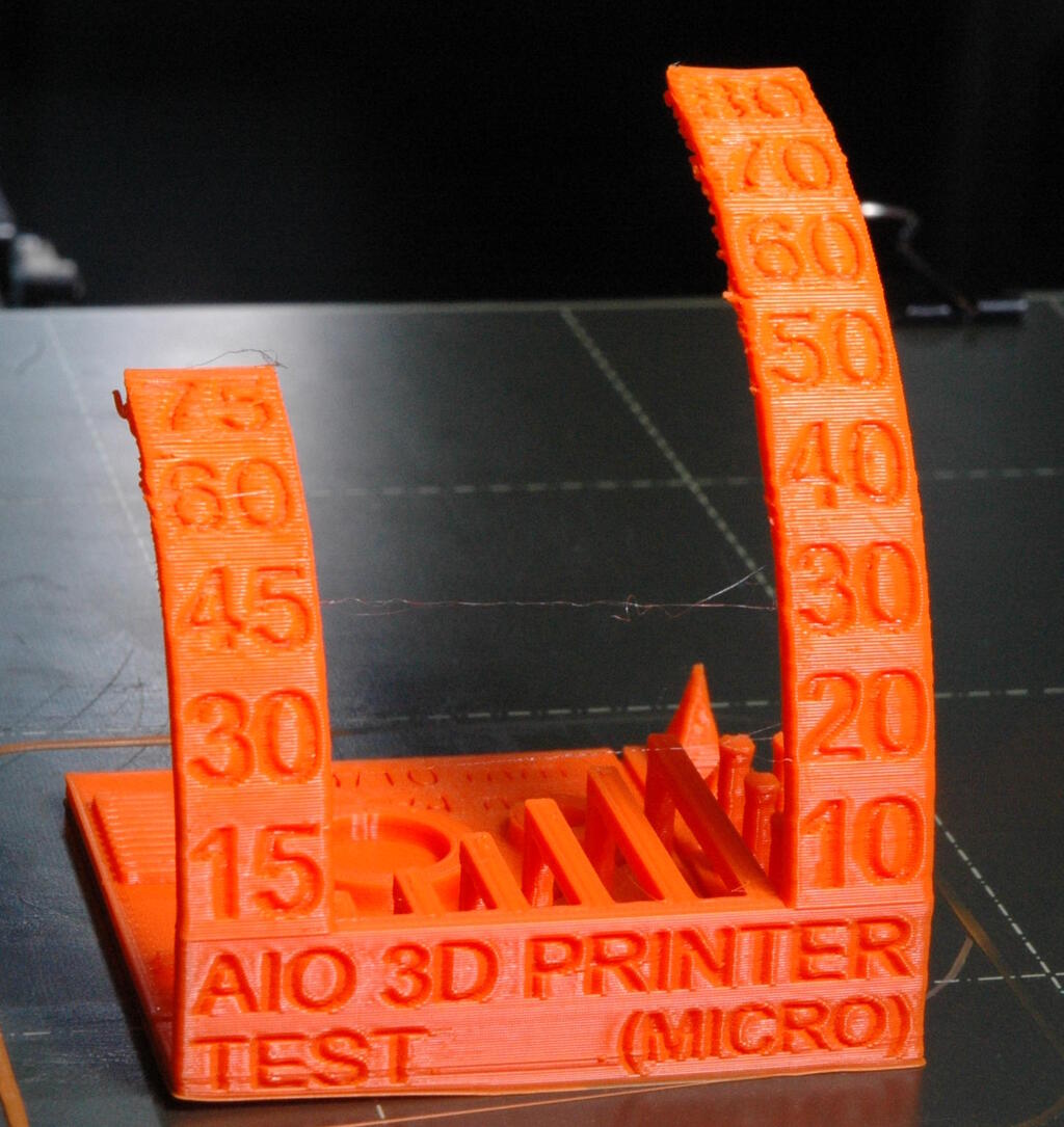
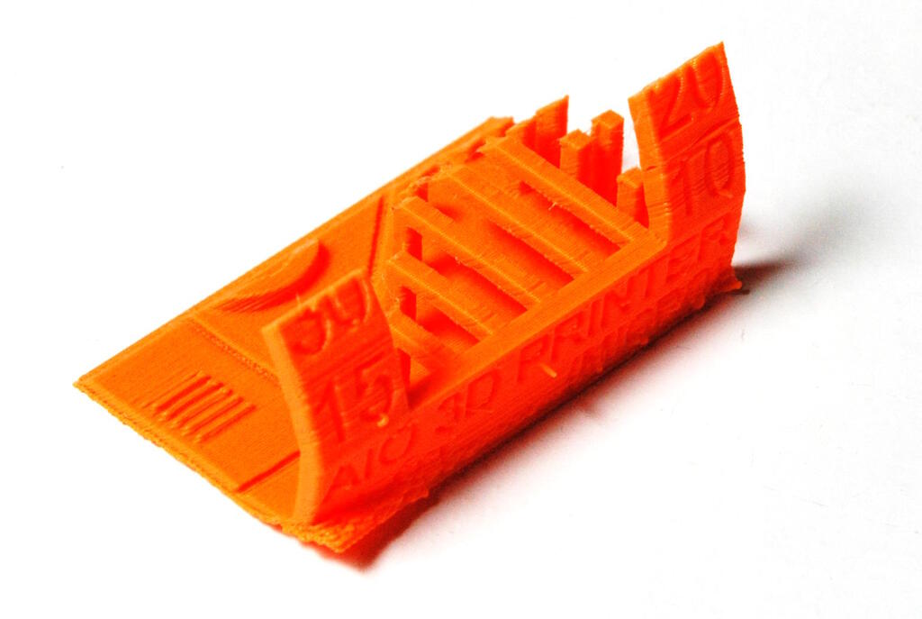
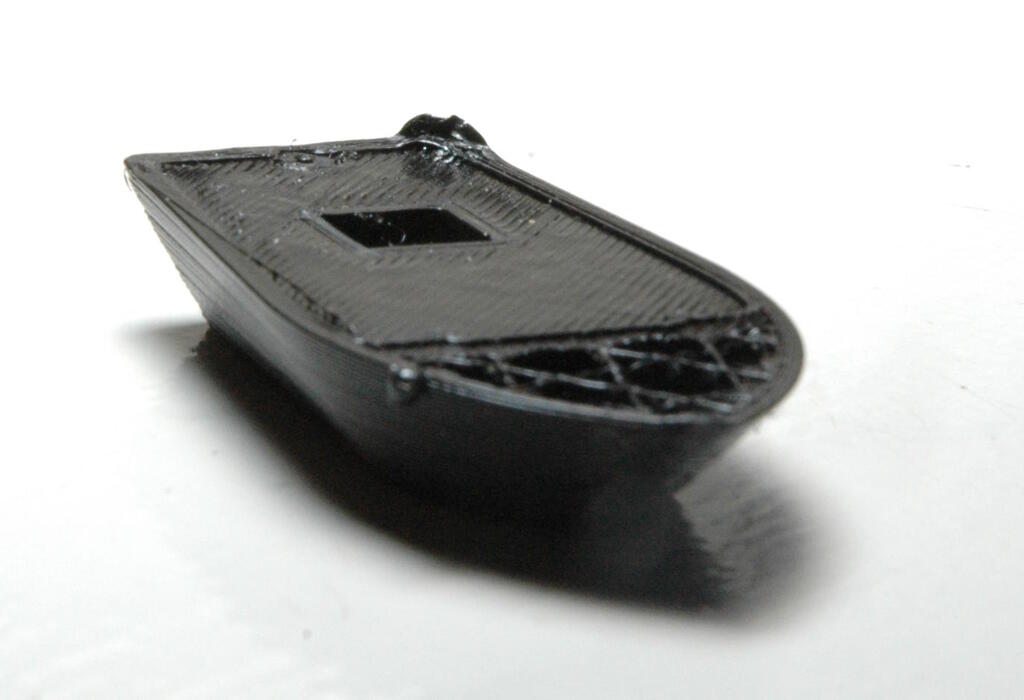
To reduce the print times, we used the MICRO All In One 3D printer test giving us enough features to compare while keeping print times low.
We wanted to use as much as possible the standard settings of the slicer but we found that the standard settings differ per printer. For example, the standard setting in Cura for the Ultimaker is a layer height of 0.15 mm where the standard setting for the Ender is 0.2 mm. So, this gave rise to the question what we actually want to compare. Do we want to compare the 3D printing workflow including the workflow of the slicer or do we want to compare the capabilities of the 3D printers . We decided that the latter is more important and since layer height is a critical factor in the quality of the print, we decided to fixate the layer height to 0.2 mm. In addition, we fixated the setting of using a skirt as well.
Another option that varies per printer profile is the infill ratio but we deemed that setting not to be critical for the quality of the print, so we consider this as part of the "standard setting". So, in summary we used the following setup to compare:
| Parameter | Choice | Note |
|---|---|---|
| Slicer | Cura | Modified Cura for the INFI-20 |
| Filament | PLA | Ultimaker uses different diameter. |
| Slicer Profile | Normal | Settings may differ per printer. |
| Layer height | 0.2 mm | Possibly overrides slicer profile. |
| Skirt/brim | Skirt | Possibly overrides slicer profile. |
Results
To make sure we had filament for all three printers, Samson and I cut 5m filament for the Prusa and Ender for the belt printer to have the spool. We failed to succesfully finish a print on the belt printer, most likely due to bed leveling issues.
Prusa
I was mainly responsible for the Prusa, so in Cura I added the following printer: Prusa ➜ Prusa i3 Mk3/Mk3s. I then chose the profile "Normal" which for the Prusa has a layer height of 0.15 mm. I therefore changed this setting manually to 0.2 mm. Cura is not aware of the filament that we use, namely Prusa filament, so we leave this to "Generic PLA". It used 10% infill for this setting. It uses a print temperature of 200 degrees Celcius and a build plate temperature of 60 degrees Celcius.
For slicing I had to rotate the model and after that I could simply slice it, transfer it to the printer via an SD card and start the print.
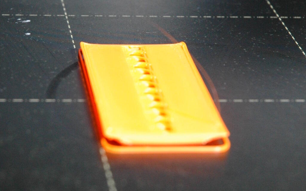
The print came out well, comparable to the print from the Ultimaker and better than the print from the Ender.
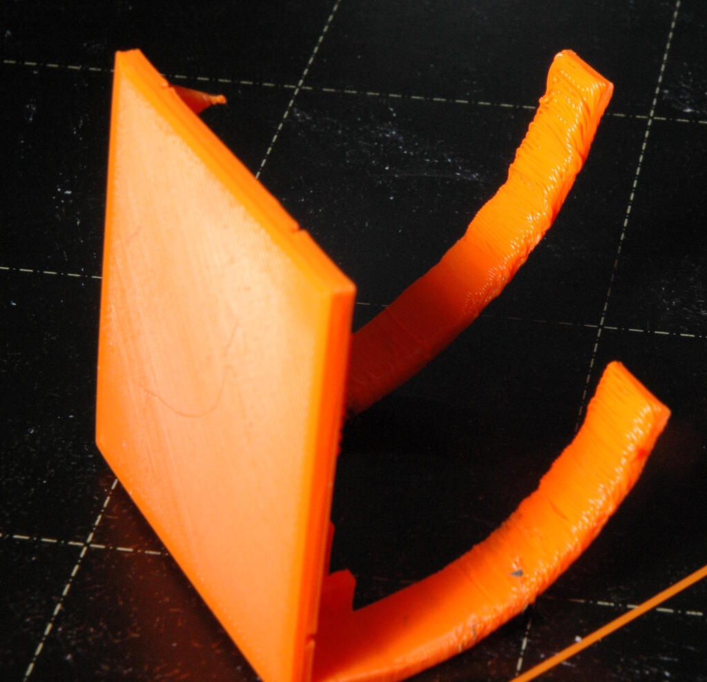
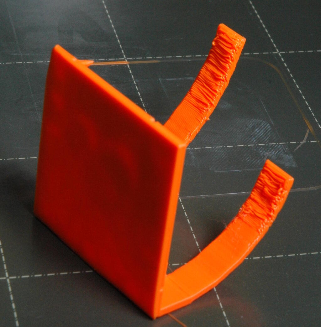
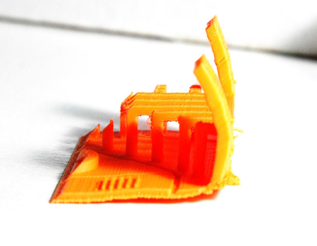
Henk was surprised by the low quality, especially of the overhang, and wondered what the result would be if we had used the Prusa Slicer. Unfortunately, we couldn't test this because the filament was in use by the belt printer. The overhang result from Prusa:
Ultimaker
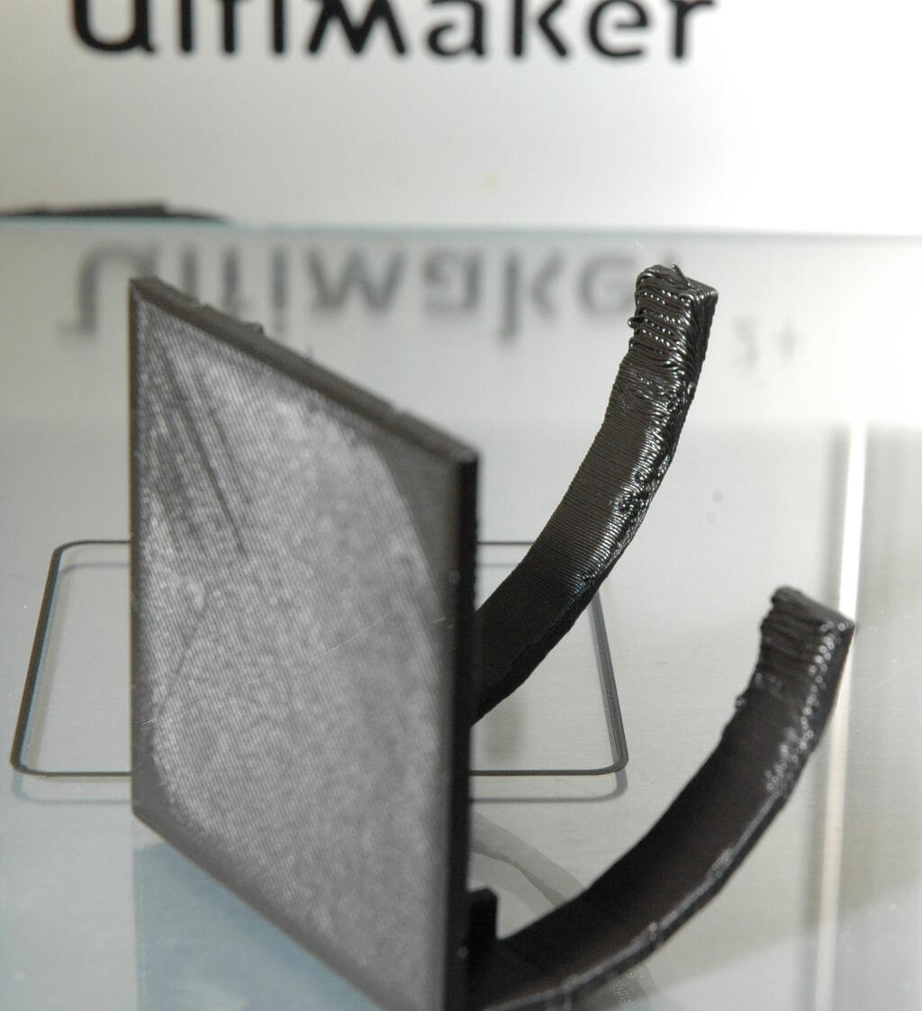
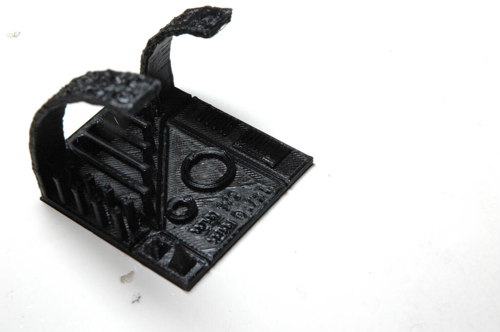
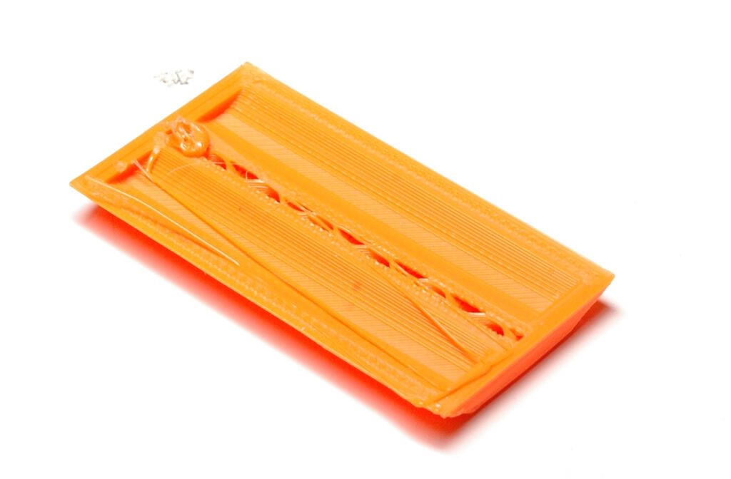
I helped calibrating this printer using a piece of A4 paper measuring the resistance. The configuration wizard is a bit annoying but in the end, we succeeded in calibrating it. The print came out well.
Most notable was the overhang problem that was similar to the problems that the Prusa version had:
Ender
We forgot to level the bed, resulting in a failing print. We tried to calibrate the build plate, but we failed to do this properly and we came to the conclusion that the build plate must be convex. I helped calibrating the bed and with some babystepping with value -0.299 we managed to successfully print the piece.
The resulting print had problems with warping:
The overhang was worse than on the Ultimaker and Prusa:
Belt printer
We failed to get a good print out of this printer. This printer is new in the lab and there is not much experience with it. However, we did see a successful Benchy print, so it is clear that the printer can print well.
The belt printer uses a modified Cura with an infinite Y axis. We were trying to place the piece correctly onto the belt within the slicer, taking into account the 45 degree angle of the print head and trying to find a way not to "air print". Michelle has screenshots of this. We found two ways to place piece but both ways failed. After careful inspection, we came to the conclusion that warping was the cause and most likely also a bed leveling issue. Unfortunately, we didn't have time to investigate more ways to solve these issues.
The print still on the belt, but you can see there are some problems at the bottom:
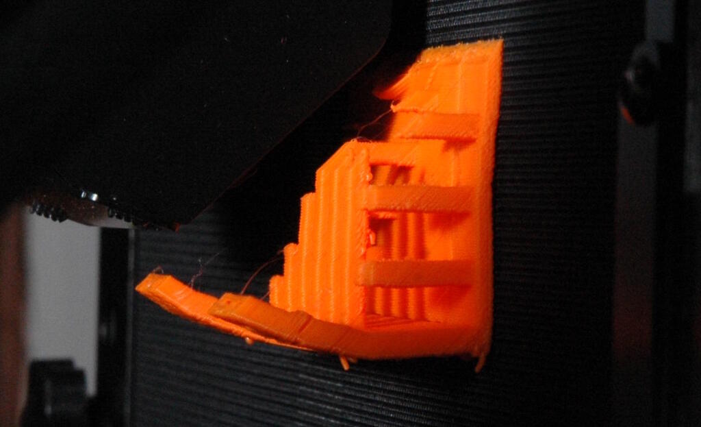
The print below the printer:
The bottom side of the printer detaches itself from the bed it seems. It seems to be warped over the complete length of the print:
A side view:
P802QS
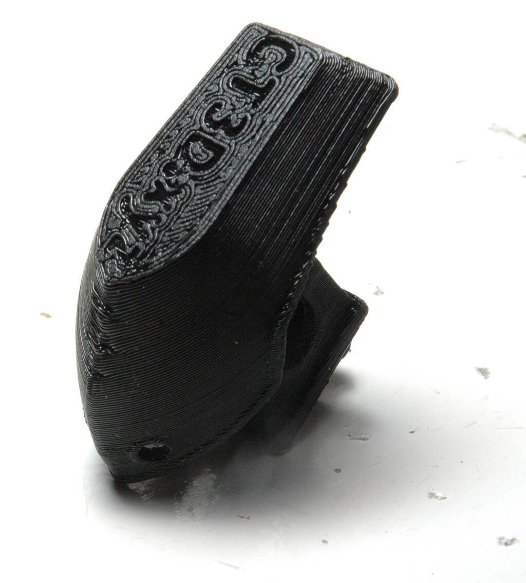
Since this is my chance to compare my printer to the lab printers, I decided to print the model on my printer as well. I didn't have the Prusa filament, but we assumed this to be no factor anyway. Since I hadn not printed for a while, I decided to service my printer which I discuss below. I also needed to set up Cura on the computer I'm working on since I normally print from a different computer.
For this printer, I needed to change the layer height from 0.15 mm to 0.2 mm and replace the brim option with the skirt option.
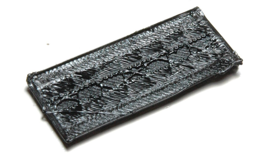
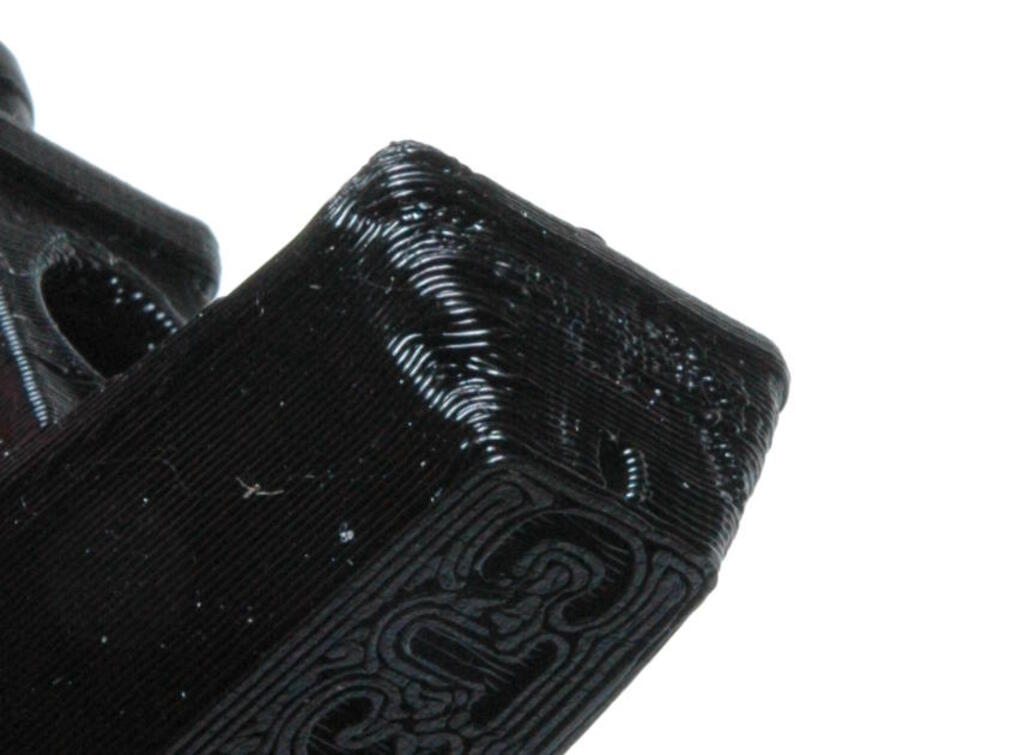
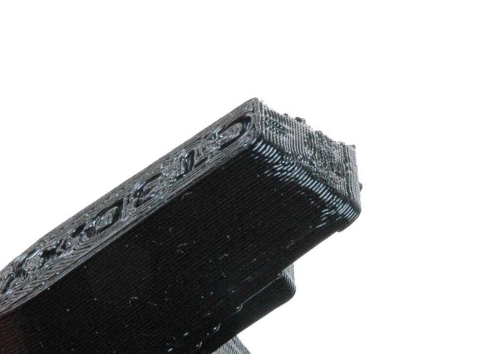
This print came out worse than the prints of the lab printers. The first couple of layers are shifted, a problem I've never had before. The pointy objects did not come out with much detail. Bridging worked surprisingly well, though. In general, the level of detail is lower than with the other printers.
Setting up the P802QS
Since I haven't printed something on my printer, I decided to service the printer. There are two problems: the belts need to be tightened and the filament is crossed. I always just ignored this problem and made sure that the filament is "loose" enough for the printer to keep printing, but since I was going to tension the belts, I tackled this problem as well. I ignored this problem because it can be very difficult to thread the filament in my extruder. Luckily, this succeed in one go this time.
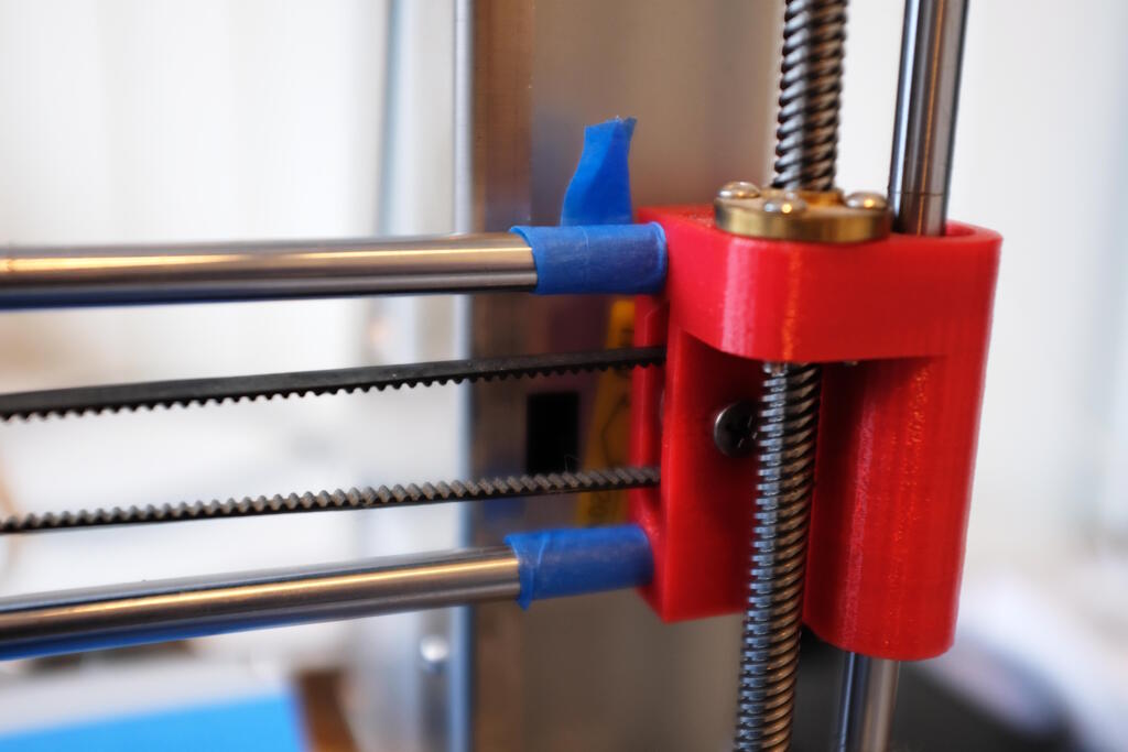
Tensioning the belts
The Y-axis belt is easy to tension with a couple of screws, but the X-axis belt is a bit more difficult. I used a bit of painters tape to keep the red plastic holder on the X-axis in place tensioning the belt.
Setting up Cura
The Zonestar P802QS is a Prusa i3 clone with a square heated bed of 220 mm and a print height of 240 mm. It came with the Repetier firmware, but I switched to Marlin. It has filament detection and auto bed leveling.
To set up the printer in Cura, I used the following settings:
| Parameter | Value |
|---|---|
| Name | P802QS |
| X (Width) | 220 |
| Y (Depth) | 220 |
| Z (Height) | 240 |
| Build plate shape | rectangular |
| Origin at center | false |
| Heated bed | true |
| Heated build volume | false |
| G-code falvor | Marlin |
I use the following start G-code to enable auto-leveling before each print:
G28 ;Home
G29 ;Auto level the bed
G1 Z15.0 F6000 ;Move the platform down 15mm
;Prime the extruder
G92 E0
G1 F200 E3
G92 E0
I use the following end G-code to move the plate such that I can remove the print:
M104 S0
M140 S0
;Retract the filament
G92 E1
G1 E-1 F300
G28 X0 Y0
G1 F200 Y200 ; Move the plate for removal
M84
I use the following settings to explain what the printhead looks like:
| Parameter | Value |
|---|---|
| X min | -27 |
| Y min | -45 |
| X max | 46 |
| Y max | 45 |
| Gantry Height | 240 |
| Number of extruders | 1 |
| Apply Extruder offsets to GCode | true |
For the nozzle settings, I use:
| Parameter | Value |
|---|---|
| Nozzle size | 0.4 |
| Compatible material diameter | 1.75 |
| Nozzle offset X | 0.0 |
| Nozzle offset Y | 0.0 |
| Cooling Fan Number | 0 |
Calibrate the extrusion
From the low level of detail, I concluded that I may need to calibrate
the extruder. To do this, I install the package
printrun
to use
the program
pronterface
that allows you to send GCode to the
printer directly.
With
pronterface
I could not initially connect to the printer
because of a faulty baud rate setting:
Got rubbish reply from /dev/ttyUSB2 at baudrate 115200:
Maybe a bad baudrate?
It turned out that I needed to switch to 250000 Bd from 115200 Bd.
To calibrate the steps per mm, I preheat the hot end and try to find a
way to accurately measure the extruded distance. For my printer that is
right above where the filament detection is. I use a piece of tape to
mark the start and then with pronterface, I use the following commands to
measure the extruded distance:
M503
to show the current firmware
settings,
M92
to show the specific steps per unit,
M83
to
set the printer in relative mode, and
G1
to extrude 80 mm.
This is the GCode conversation with my printer:
>>> M503
SENDING:M503
echo:  G21    ; Units in mm (mm)
echo:  M149 C ; Units in Celsius
echo:; Filament settings: Disabled
echo:  M200 S0 D1.75
echo:; Steps per unit:
echo: M92 X80.00 Y80.00 Z400.00 E97.80
echo:; Maximum feedrates (units/s):
echo:  M203 X150.00 Y100.00 Z8.00 E50.00
echo:; Maximum Acceleration (units/s2):
echo:  M201 X2000.00 Y800.00 Z100.00 E5000.00
echo:; Acceleration (units/s2): P<print_accel> R<retract_accel> T<travel_accel>
echo:  M204 P1000.00 R3000.00 T3000.00
echo:; Advanced: B<min_segment_time_us> S<min_feedrate> T<min_travel_feedrate> X<max_x_jerk> Y<max_y_jerk> Z<max_z_jerk> E<max_e_jerk>
echo:  M205 B20000.00 S0.00 T0.00 X10.00 Y10.00 Z0.30 E5.00
echo:; Home offset:
echo:  M206 X0.00 Y0.00 Z0.00
echo:; Auto Bed Leveling:
echo:  M420 S0 Z0.00
echo:; Material heatup parameters:
echo:  M145 S0 H200 B60 F0
echo:  M145 S1 H230 B100 F0
echo:; PID settings:
echo:  M301 P22.20 I1.08 D114.00
echo:; Z-Probe Offset (mm):
echo:  M851 X34.00 Y1.00 Z-2.40
echo:; Filament load/unload lengths:
echo:  M603 L0.00 U100.00
echo:; Filament runout sensor:
echo:  M412 S1

>>> M92
SENDING:M92
echo: M92 X80.00 Y80.00 Z400.00 E97.80

>>> M83
SENDING:M83
>>> G1 E80 F50
I measured exactly 80 mm, so this setting was correct for my printer.
Design and 3D Print a Battery Case
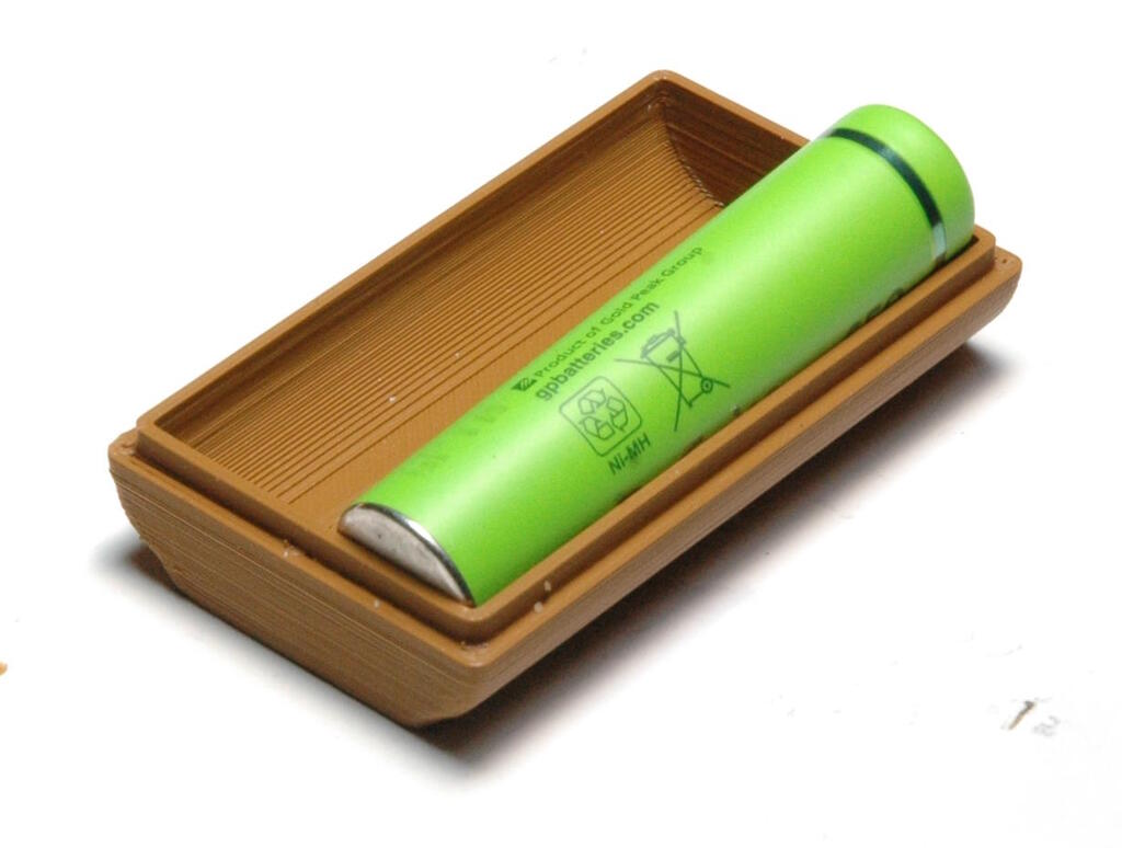
The goal is to design and 3D print an object that cannot be created easily with subtractive methods. I have in mind a case to hold my chargeable batteries for my flashes, parametric in the number of batteries and for the battery size.
Design Rationale
The case should be as small as possible, parametric in the battery count and the size of batteries (AA or AAA). The case should follow the contours of batteries, making it difficult to fabricate with subtractive methods because the underside is round. I would like to be able to close the case as well preferably with the lid attached to the case.
In terms of spiral development, I have the following in mind:
- iteration 1: the case for two batteries
- iteration 2: the lid for that case
- iteration 3: experiment with flexures to fixate the lid to the case
For the first two iterations, I wanted to make use of the friction between the lid and the case by means of the separate layers. I want to create an inside rim of several layers high and an outside rim of several layers high that "rub" against each other to make the case and lid close well. For the third iteration, I could make use of a flexure structure.
The Parameters
I measured the dimensions of AA and AAA batteries roughly to have something to work with and set up a list of parameters to control it. My idea was to fine tune the dimensions after a print by changing tolerance values. I wanted to make sure that I have tolerances for the X and Y direction separately just to make sure I had the flexibility to adjust the sizes if needed.
To explain this design, I'm going to separate the parameters into four
groups: constants, parameters, tolerances, and variables. For constants I
have the values
length_AA
,
diameter_AA
,
length_AAA
,
and
diameter_AAA
. These values can be chosen as parameters. They
are constant because this size does not change.
The set of parameters that I used is:
| Parameter | Value | Note |
|---|---|---|
| length | 42.5 mm | Refers to the length of an AAA battery |
| diameter | 10.25 mm | Refers to the diameter of an AAA battery |
| nr_batteries | 2 | The number of batteries in the case |
| thickness_wall | 2 mm | The thickness of the enclosing walls |
| height_rim_idea | 2 mm | The height of the rim not compensated by tolerances |
The set of tolerances:
| Tolerance | Value | Note |
|---|---|---|
| tolerance_battery_x | 0.50 mm | Add to the diameter of the battery in the X direction |
| tolerance_battery_y | 0.50 mm | Add to the length of the battery in the Y direction |
| tolerance_rim_x | 0.10 mm | Subtract from to the width of the rim in the X direction |
| tolerance_rim_y | 0.10 mm | Subtract from to the width of the rim in the Y direction |
| tolerance_rim_z | 0.10 mm | Subtract from to the height of the rim in the Z direction |
The set of variables all depend on the above and are typically computed
from the above constants, parameters, and tolerances. I'm not going to
list the computations here, but the variables are:
thickness_rim_y
,
thickness_rim_x
,
height_rim
,
length_inside
,
diameter_inside
,
length_outside
,
diameter_outside
,
length_middle
.
The Design
It was difficult to understand how to approach designing the case. I could exploit symmetry of course, but should I do boolean operations on various bodies or should I design several sketches within the same body. Since exporting to STL requires you to select a single body to export, I chose the single-body approach with several sketches.
Below is an image of the design with 3 AAA batteries. It has 3 compartiments, the bottom is round which is difficult to do with subtractive methods and on top there is a rim.

The case has two side parts that are mirrored, and a middle part that is mirrored here as well. The side part is designed by using four sketches that are selectively padded or pocketed. This padding and pocketing is done in two dimensions symmetrically (so towards the viewer and away from the viewer). So for example, the rim is created by padding a block symmetrically around the XY plane 44.8 mm which is then pocketed 43 mm symmetrically around the XY plane, leaving us with a rim of 0.9 mm on the front of the XY plane and the back of the XY plane.
To understand how the sketches create this structure, the following image contains the sketches on the XY plane together with the resulting body by means of padding and pocketing:

The sketches separately are:

For the middle part, the case together with sketches is:

The sketches separately are:

Printing the Case
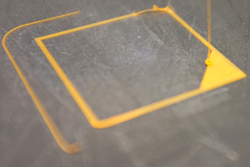
Printing the case proved to be very challenging but there are plenty of lessons to be learnt here. I first tried the print on my own printer but this failed because the case became loose from the bed because of the corners curling up:
Since my test confirmed that my printer did not have good quality and I used the Prusa slicer instead of the Cura slicer that I've always used, I initially assumed it would be a Prusa calibration issue. So, I decided to use the Prusa instead.
I expected this print to be easy for the Prusa with perhaps some minor problems with the round side. However, since the case is small, I didn't think this would be a major problem.
Interestingly, the Prusa printer had the same problem as my printer with the corners curling up:
This caused the print to shift as can be seen here:
I repeated the print several times with different settings without being able to print succesfully. What I experienced is the following:
- All four corners curl up, already at the first few layers.
- As the corners solidify, the print head may run into it, shifting the print.
- The printer becomes clogged.
At the time I didn't have a good explanation for it but I now think all is related, so the corners curl up, perhaps also clogging the printer trying to extrude while there is already material there.
For this print I used the same method as with testing the 3D lab printers, start from the standard settings and modify one by one. The following section describes the print settings and debugging this print.
Debugging the Case Print
Initially, I discarded the result from my own printer because the quality of the print test was not as good as that of the lab printers and I used the Prusa slicer instead of Cura. However, now that the Prusa shows the same symptoms, this printer has become relevant again, so I will list the settings of this printer as well.
So, for all prints, I used the Prusa slicer because Henk recommended us to use that. I used the default settings of the slicer and note where I made a difference.
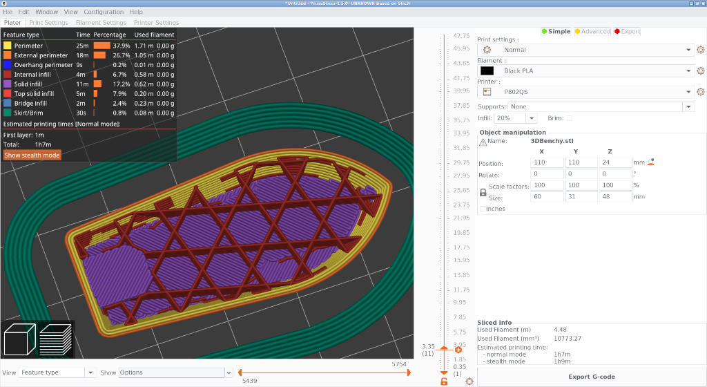
P802QS
At the time of printing, I thought I used the standard settings of filament, but in writing down this very documentation, I noticed that I didn't use the standard settings for filament. The reason is that the Prusa Slicer's configuration Wizard asks you to define a temperature setting for your printer and I chose 215 degree Celcius as extrusion temperature and 60 degrees for the bed. I chose these values because I remembered that I usually print with these settings when I use Cura. However, it turns out that the Prusa Slicer default setting for temperature is 200 degrees Celcius.
The print settings were:
| Setting | Value | Note |
|---|---|---|
| Layer height | 0.3 mm | |
| First layer height | 0.35 mm | |
| Fill density | 20% | |
| Fill pattern | Stars | |
| Nozzle temperature first layer | 215° C | Not a standard setting |
| Nozzle temperature other layers | 215° C | Not a standard setting |
| Bed temperature first layer | 60° C | Not a standard setting |
| Bed temperature other layers | 60° C | Not a standard setting |
| Keep fan always on | false |
The print that came out and was aborted because it was shifted:
Prusa
For the Prusa, I used the following settings:
- Print settings: 0.20 QUALITY
- Filament: Prusament PLA
- Printer: Original Prusa i3 MK3S & MK3S+
This boils down to the following settings to compare with the settings above:
| Setting | Value | Note |
|---|---|---|
| Layer height | 0.2 mm | |
| First layer height | 0.2 mm | |
| Fill density | 15% | |
| Fill pattern | Gyroid | |
| Nozzle temperature first layer | 215° C | |
| Nozzle temperature other layers | 215° C | |
| Bed temperature first layer | 60° C | |
| Bed temperature other layers | 60° C | |
| Keep fan always on | true |
What we observed with these settings was the following: The print failed because the case came loose from the bed. We also observed that all four corners of the print curled up during printing. Each time the print head passed, it would press down the curled corner because it was still soft.
What we didn't know whether the curled corners had something to do with the print shifting. While discussing with Henk and Asli, Henk asked me if I cleaned the bed which I did. In the end we had several hypotheses:
- The corners are too pointy to be printed correctly.
- The plate is not sticky enough.
- The printed material is rocking due to the print head bumping into the curled corners.
- The filament settings are wrong.
Although I would like to change only one parameter, we are dealing with long print times and Samson wanted to print as well, so I changed the following. Henk recommended me to use the setting "0.20 SPEED" instead of "0.20 QUALITY" because it was simply a case. Our filament wasn't Prusament filament but just regular Prusa PLA, so I switched to "Prusa PLA" from "Prusament PLA" which effectively changed the temperature for other layers from 215 to 210. I don't think this is enough of a change to have effect on the print knowing that I had the same problem on my printer.
I found the most likely hypothesis to be the first one: the corners are too pointy to be printed correctly. I wanted to add a fillet to the sides, but Asli advised me to use a chamfer instead because of this uses a maximum angle of 45° and works best with prints. This is the modified design:

However, this had the same problem of curling corners and the printer did not complete in this case because the filament was blocked. After inspection, it turned out there was a small blob in the filament, possibly caused by extruding over an elevated corner.
Back to the P802QS
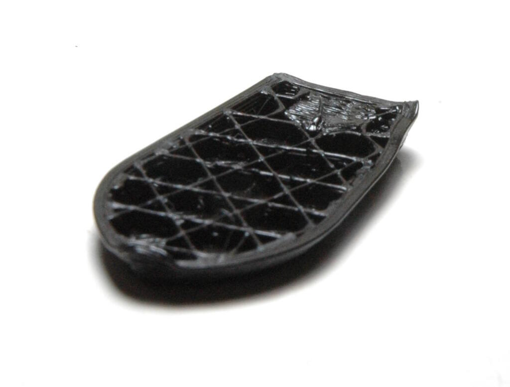
Now that I know that the print fails on the Prusa as well, I wanted to investigate more, but I could only do that on my own printer. Since the 3DBenchy has similar upward wall, I decided to print this model on my printer, with the same default settings as above. The print came out quite good:
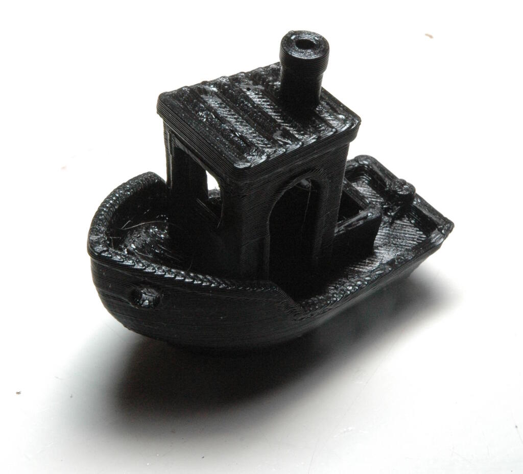
There were some artifacts that looked similar to the battery case:
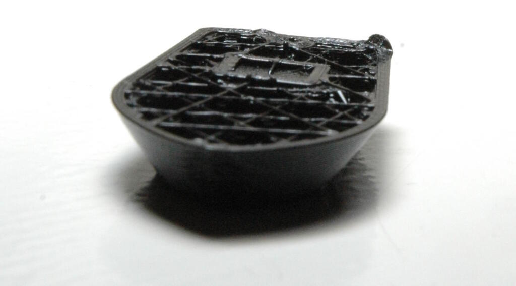
Interestingly enough, the front corner and the back left corner are curling but not the back right corner. A photograph of the corner that was better:
A photograph of a print stopped in the middle:
I experimented with setting the nozzle temperature to 200° C but this didn't matter much:
Another experiment was to set the bed to 40° C after the first layer. This made it better, but wasn't the solution either:
These experiments were enough for me to discard the last three hypotheses about the plate not being sticky enough, the printed material rocking and wrong filament settings. The filament settings are probably not ideal, but they are not so bad that they cause the curling which is quite extreme.
The fact that one corner is curling has most likely to do with the infill that is quite a bit more prominent at those corners than in the corner without curling:
This means that I most likely have to tweek the perimeter/infill settings. This corner curling doesn't explain why it would be the case for the battery case because there is no infill there. It may be the case that the lines are too thick, but the extrusion has been calibrated.
After thinking all this through, I came up with a new hypothesis about the rounding on the side of the case. A round corner has a very small angle with respect to the print bed which is difficult to print because the printer has to effectively "air print" or at least for a large part. So, the hypothesis is that the rounding at the bottom provides too weak a structure to support the corners that are quite pointy as a result of this rounding. We already concluded that the chamfer was not a solution, but perhaps the basis is simply not good enough. So, I decided to change the sketch for the side from the following sketch:

to the following sketch with a minimum angle of 45° with respect to the bed:

I also used a fillet on the corners to make the corner even better suited for printing. The resulting design:

This design came out much better:
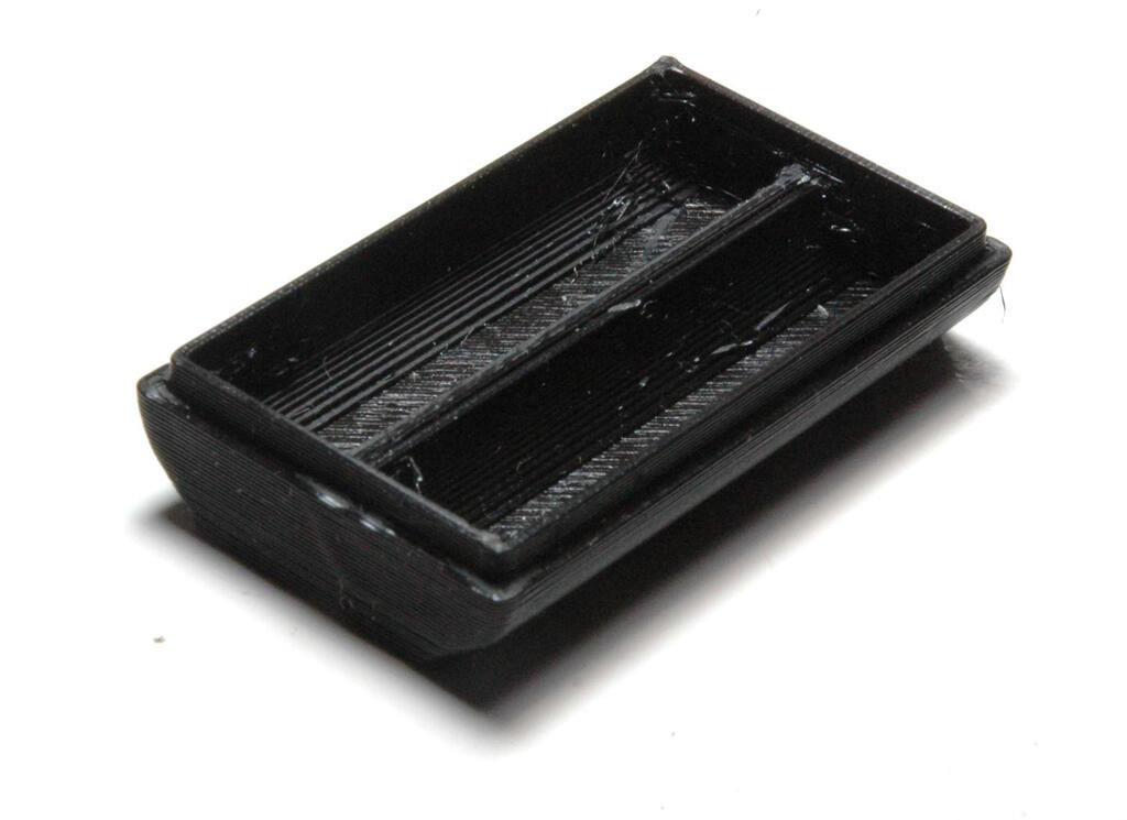
Interestingly enough the print on the Prusa failed again! This time it was again the clogging. We think the filament is simply to old. I was told that it had been lying in the lab without a plastic cover. The following print was done with different filament and a little bit of glue applied to the bed:
3D Scanning an Object
Although I did a 3D scan that week, I did not have time to document my experiences because of all the trouble I had with 3D printing, something I prioritized over 3D scanning. For my final project, I would like to have a rim that fits my face perfectly, so I decided to scan my head and create a 3D model of the rim of the device that I want to make.
Scanning Objects
Michelle showed us various options to scan objects. Below she showed one option using her phone and a piece of A4 paper with a checkered pattern that the app on the phone can analyze:
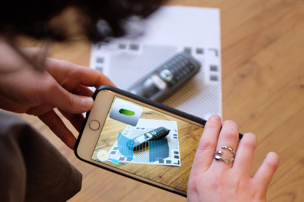
Unfortunately, these apps are proprietary and my not-so-smartphone without any Google software most likely doesn't have a good 3D scanning application. I checked F-Droid but there appear to be no 3D scanning apps.
Michelle also showed us how to use the Sense 2 3D scanner and we tried capturing each other heads. Michelle scanned my head, I scanned Samson's head and Samson scanned Michelle's head. You can see me here scanning Samson:
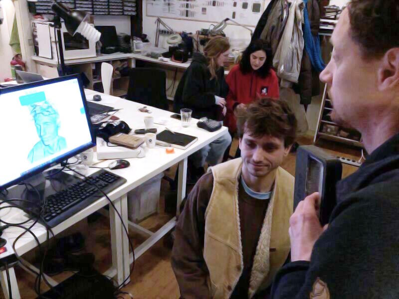
In the software (that is unfortunately proprietary as well), we chose the option "Head" (out of other options "Object" and "Body") and then we press "Scan". You then move around the head watching the application for green parts to appear, parts that have been succesfully scanned. We have to move slowly because the software can loose tracking or you can move to fast. After your are satisfied with the scan, we can choose "Finish" after which the software processes the input data to create a mesh.
After this there are various options available to improve the scan of which Repair ➜ Solidify is an essential tool that plugs holes in the scan.
We saved the file as a VRML file (
.wrl
) and as a Wavefront file
(
.obj
) and a very flattering render of the VRML file with textures
is here:
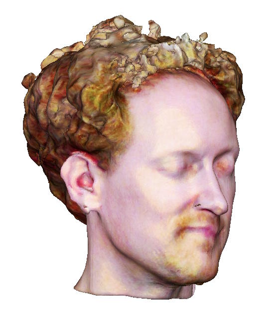
The colors were all messed-up, so I did some post processing. This is a screenshot from FreeCAD where I made the background white. In Gimp, I applied the Curves tool and increased the "Value" curve, decreased the "Blue" curve and then I reduced the saturation.
Processing the 3D Scan
I want to process the 3D scan of my head such that it becomes a cutout of the area around my eyes and nose. With this cutout, I will have the exact measurements to make a rim for my device in which my face fits.
The tool to manipulate meshes is Blender but since I'm not familiar with Blender, I need to investigate how the software works.
Importing the VRML file
We import the file with File ➜ Import ➜ X3D-Extensible 3D (.x3d/.wrl). This takes some time and the first thing we notice is that the textures are not visible and that the model is rotated.
Rotate the Object
We are in "Object Mode" and with "R" we can rotate according to the cursor. We can click on any of the axes to view the object from the perspective of that axes, so we can rotate the object properly. I need to rotate it along the Y-axis. I also need to put it upright, by rotating it along the X-axis.
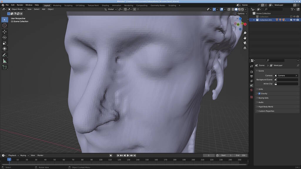
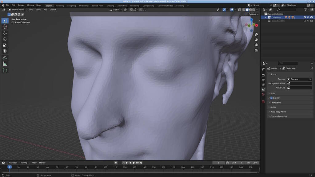
Smoothen the Surface
One side of the nose is particularly wobly, so I need to improve on that. I followed the following YouTube Tutorial that was quite helpful. As suggested in the video, I first duplicate the Collection by right-clicking it, and select "Duplicate Collection".
In the video explains that it is better to lower the quality of the mesh a bit to make it easier to sculpt on, so let's follow that. At the bottom right, we select the "Modifier Properties" (the wrench) and "Add Modifier" "Decimate" that we apply with a ratio of 0.4. We then add the modifier "Smooth" with "Factor" 0.9 and with the value 2 for "Repeat".
From here, we will move to "Sculpt Mode" where we use the "Draw" tool to fill the "hills" in the uneven parts in the left side of my nose. With "F" we can change the diameter of the tool and it is useful to set the strength as well. Besides using the "Draw" tool, I also used the "Smooth" tool to make the surface nice and smooth.
The before and after:
Cut Away the Unwanted Parts
From the resulting mesh, I want to cut out all the parts that are not of interest, so I want to keep part of the forehead, part of the nose, and the eyes. To accomplish that, I will add rectangular shapes and perform boolean operations.
First, we add a cube by doing Add ➜ Mesh ➜ Cube that will appear at the cursor. We don't see it before we make the shape of the head invisible. To make it bigger, we use "S" to manipulate the size and "G" to move the object elsewhere. We can then make the head visible again and scale and move the cube such that it overlaps with the parts that we want to cut away.
We then select the head, go to the modifiers, add a modifier "Boolean" and select the cube as "Object". If we then do "Apply", the part covered by the cube is removed. We can then move the cube to other parts that we want to cut away and repeat the same procedure.
Move the Object
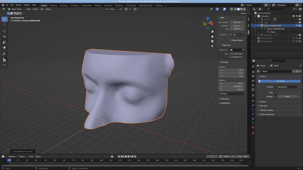
Finally, we want to move the object to the XY plane. As I didn't know how to do that and it was actually quite difficult to do, it makes sense to document it here: I go to "Edit Mode" and choose "Face Select". I then select the bottom face of the object and do Shift-S and choose "Cursor to Selected" to move the cursor to this face.
Then we go to "Object Mode" again and right click the object and do "Set Origin" ➜ "Origin to 3D Cursor" to place the origin of the object to where the cursor is. We enable the sidebar by "View" ➜ "Sidebar" and there we have a tab "View" with a context menu "3D Cursor", where we can set the cursor location precisely. We set it to (0, 0, 0).
Then we select the object again, press Shift-S and do "Selection to Cursor". The resulting geometry is then:
Hopefully this is something I can use in the molding and casting week.
Reflections
Allthough all three printers we tested can print well, it is clear that the Prusa is the best. It is easy to set up and it is consistently printing well. We used Cura as slicer but I've worked now with the Prusa slicer as well and I somehow have more faith in this slicer.
It is unfortunate that the SainSmart INFI 20 is not really accessible to me because it requires a custom and proprietary Cura that only runs on Windows. This looks like an interesting license issue, by the way, because Cura is released under LGPL, which means that you can embed Cura as a library in proprietary code. However, if you make any modifications to Cura as a library, you are obliged to publish these changes under the same license. Since the SainSmart slicer looks suspiciously like Cura, it is most likely that they don't use Cura as a library, but just extended Cura. In that case, they should release the slicer under LGPL as well.
Although the Prusa was the best performing printer, I had bad results on the Prusa nonetheless. Although I'm writing this later, within this week was I was randomly chosen to be reviewed by Neil and he had the hypothesis that we used old filament, something we hadn't considered yet. He explained that filament in general is hygroscopic and that old filament has a chance to absorb water leading to bad prints. I looked up the effects of old filament and there are a couple of indicators that seem to confirm Neil's idea:
- PLA may swell causing blockage at the nozzle.
- The print may not stick well and may show warping.
Since the filament we used had been laying around in the lab for a while without a box and the fact that the print succeeded with different filament makes this the most plausible theory so far. Additionally, I experienced quite some blockages with this filament.
By the way, I've now printed several things with the Prusa and this same old filament with reasonable results, so I think the combination of old filament and my design that is particularly prone to warping resulted in this bad experience.
As for the 3D Scanning, I'm quite happy with how that went. The scan of my face is not particularly good, but I think it is good enough to be used in my final project. It is unfortunate that this technology is not accessible to someone like me that does not want to make use of proprietary software. If time permits, I will try to find open solutions for that.
Tasks
Fab Academy
- Test the design rules for your 3D printers.
- Design and 3D print an object that cannot be easily made subtractively.
- Explain why the document cannot be easily made subtractively.
- 3D scan an object.
- Explain what you learned from testing the 3D printers.
Personal
- Improve the parameters of the 3D design.
- Add a lid.
- Add flexures to the lid.