The Laser Cutter
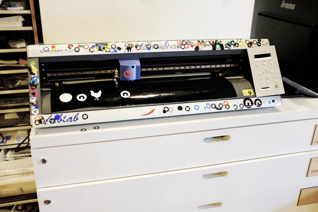
The Waag Fab Lab has the BRM Original Laser Machine. It appears to be a Dutch machine and unfortunately there is no online documentation about the laser cutter. Henk modified the controller of the machine a couple of years ago to support more input formats.
General Overview
A laser cutter is typically a 2-axis machine and this one is no different although the height of the bed may be changed. The 2 axes have end-stops and on start-up the machine "homes" to find the end-stops before returning to the previous position.
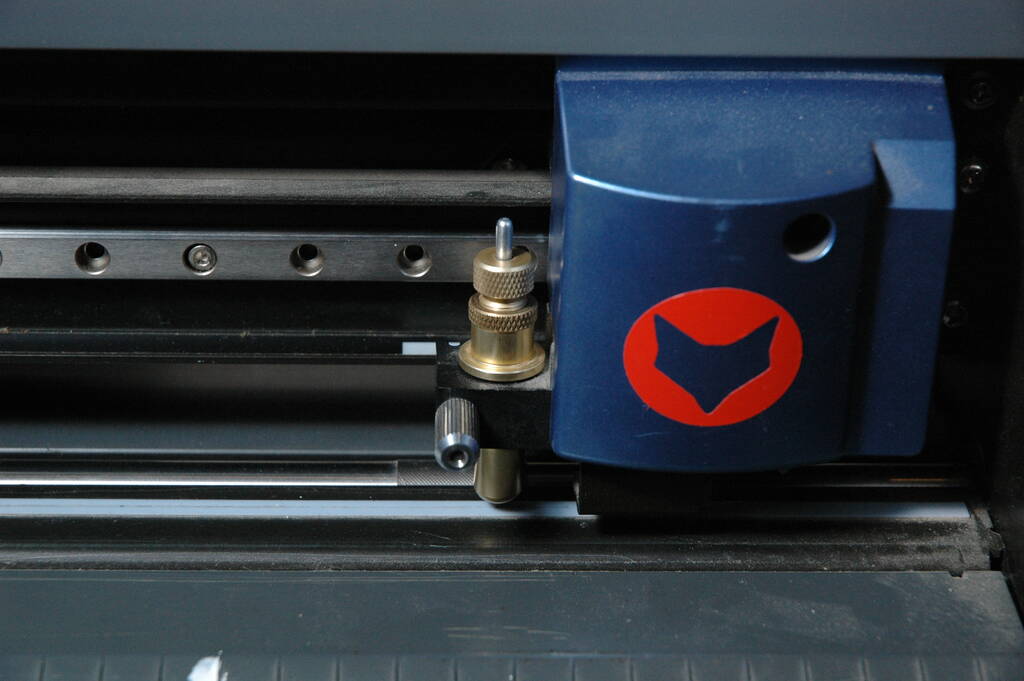
The water-cooled laser is in the back and the beam of the laser is directed toward the laser head that contains a lens that focuses the beam:

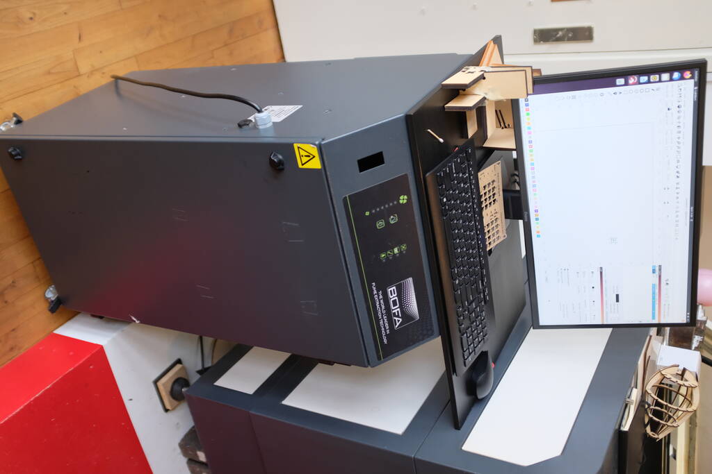
The above picture also shows the honeycomb system that serves as a means to filter the air. There is a BOFA air filtration system in place:
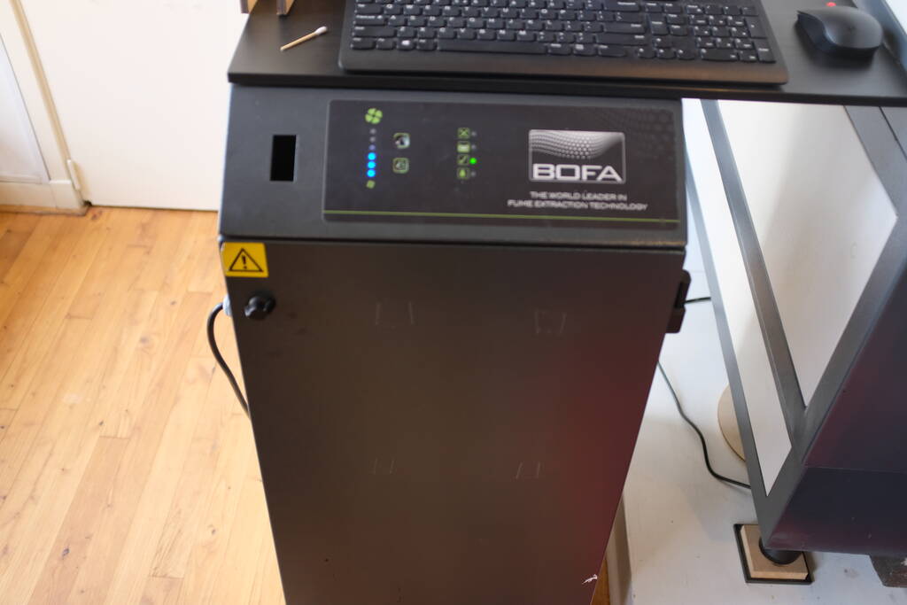
This is located underneath the computer station to control the laser cutter:
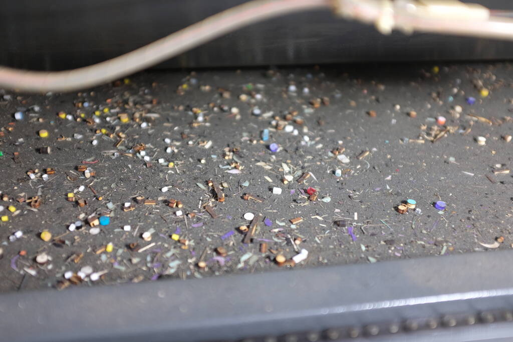
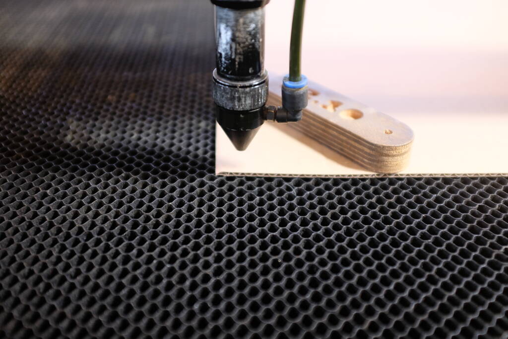
The underside of the honeycomb structure catches small particles as result of the laser cutting:
The laser gives light pulses that burn or melt material away. The following picture shows the pulses in plexiglas:

Operating the machine
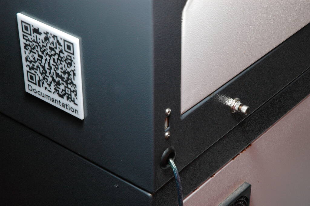
The laser can be turned on via the panel on the right hand side, turning the key (1), turning on the power (2), and right before the actual cutting, turning on the laser head (3). The panel should not be used otherwise.
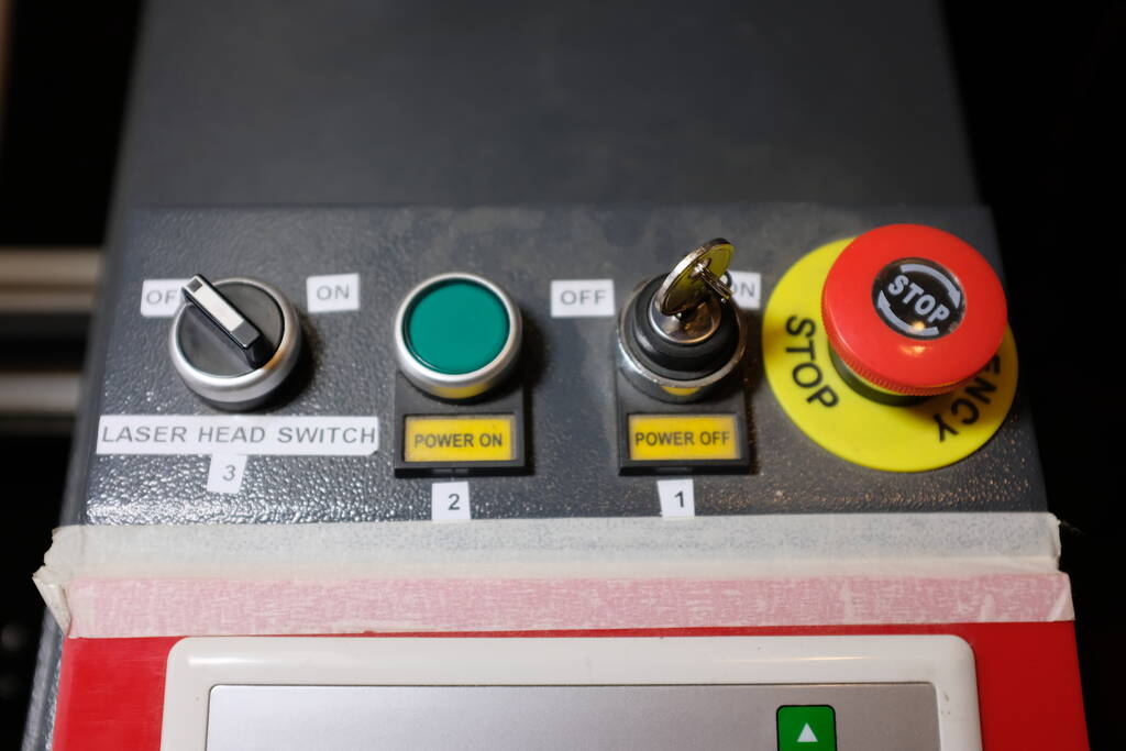
Switching on the laser head gives an audio signal and from that moment on it is not allowed to leave the red platform while a laser cutting job is in operation. When a job is finished, there is an alarm to notify the user.
To operate the laser cutter, the computer station has as software LightBurn, which unfortunately is proprietary software. I didn't have time, but I will ask Henk if I could use an alternative for that. It's not that big of a problem since the software is not running on my machine, but I would be very interested in learning if we can control it with open source software as well.
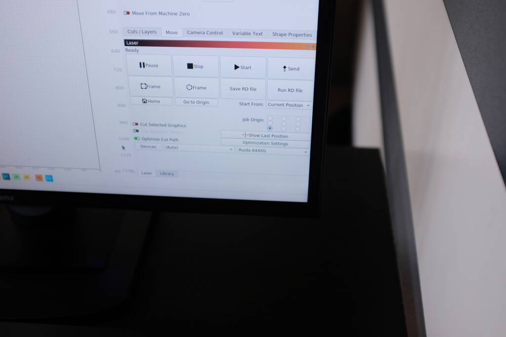
An important setting in the software is the Job Origin that uses the current position as origin in relation to the input that is visualized on the screen.
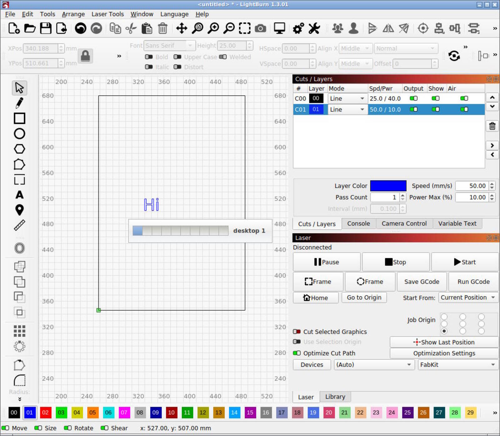
The "Frame" button shows the outline of what is being laser cut and the "Start" button starts the job. I will use mainly SVGs for laser cutting and the various lines in the SVG that represent the paths for the laser cutter to follow can be given different colors for different speed and power settings. Below you see a square (black line) with an engraving in blue. The settings for the layers are at the top right:

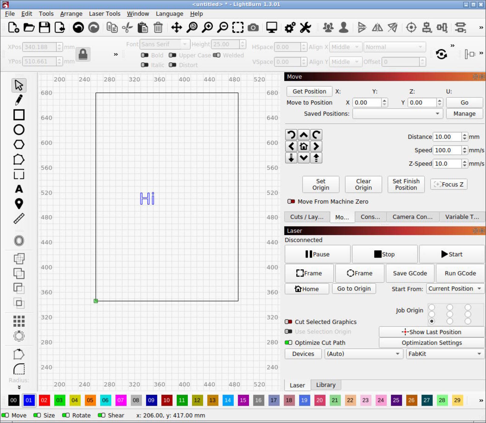
Another frequent operation is to move the laser head.
If the job has been set up, the material can be placed on the bed underneath the laser head corresponding to the origin corner as discussed above. Based on the material, we need to focus the laser head. The rim below should be turned to the left from the bottom perspective to loosen the focus tube. We can move the tube up or down to rest it on the "focus stick"
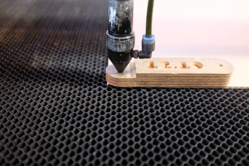
To keep focus, it is necessary to keep the material down and flat on the bed. In the picture below, we use the focus stick to achieve that.
Before actually running a job, it is necessary to turn on the air filtration by using the power cord with a switch behind the machine:

Right before turning on the laser, we can use the "Frame" button to verify the outline of the laser. We can then turn on the laser and press start to cut.
In case of an emergency, there is the red button on the panel. In case of a fire for example, there is a plant sprayer with water to estinguish the fire:
Maintenance
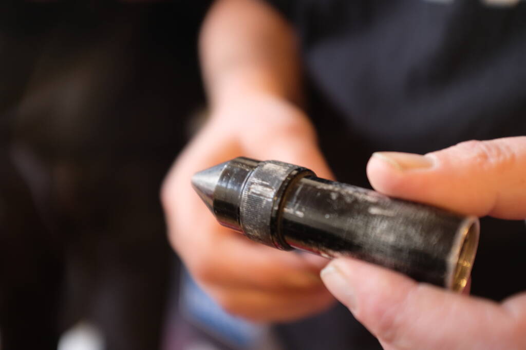
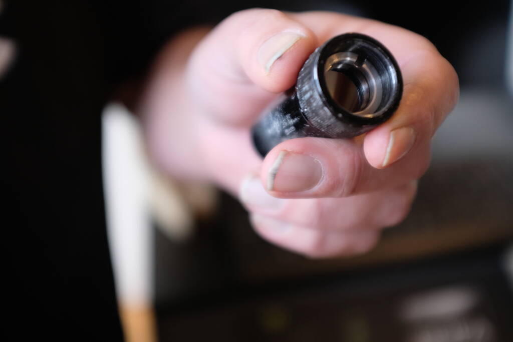
The lenses and mirrors should be cleaned regularly with alcohol as the dust can heat up breaking the lenses. The lens is in a tube that can be screwed in or out to focus the laser beam. Below a picture of the focus tube removed from the machine:
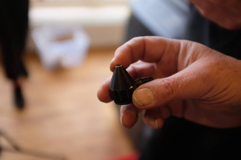
The tip of the tube can be removed for access to the lens:
The lens in the laser head:
Removing the lens:

The focus tube has a connection for an air tube blowing air to prevent the material to catch fire:
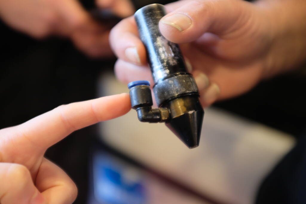
This tube should be connected to that connection:

Like this:
The filters of the BOFA should be cleaned regularly as well, a filter for large particles and a HEPA filter:
Characterizing the Laser Cutter
This was a group assignment and we measured the kerf of the laser beam, focusing of the laser, and various power/speed ratios for different materials. We used yellow plexiglas, cardboard, and multiplex.
Kerf
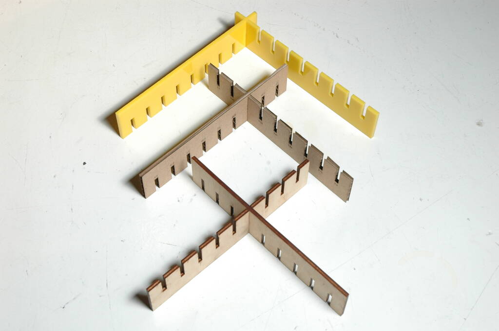
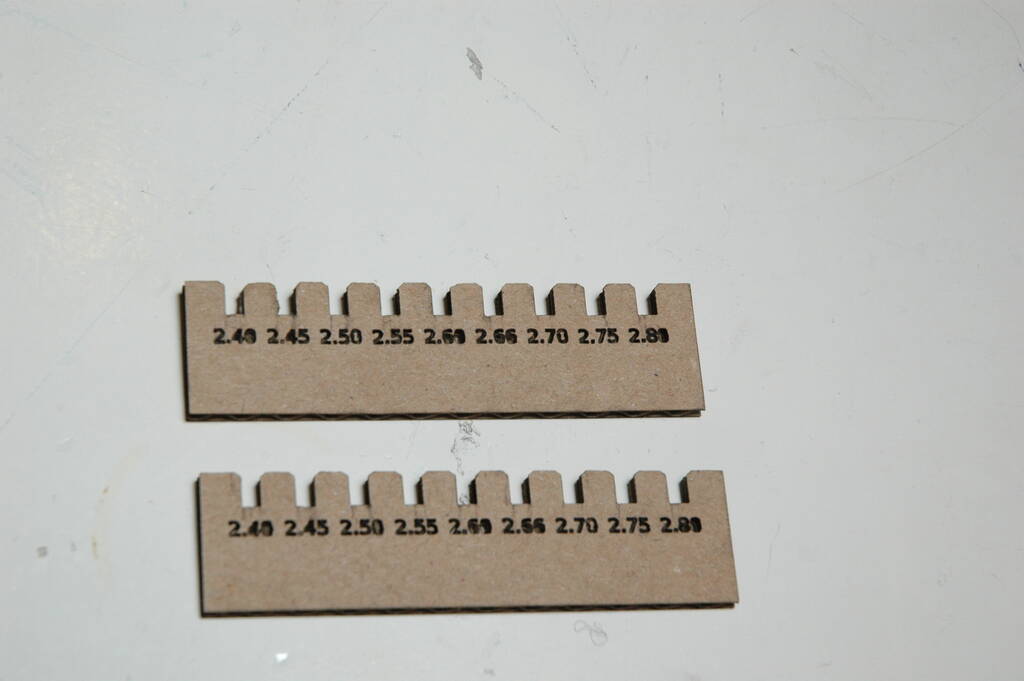
Michelle measured the kerf by cutting 10 lines that should be 10 mm, but she found it to be 9.81 mm, making the kerf 0.21 for cardboard. She measured 0.15 mm for would and 0.22 for acrylic. She also created combs for our three different materials and I found the following thickness setting the best for joining the two combs: plexiglas 2.80 mm, cardboard 2.50 mm, and the multiplex 2.95 mm.
Power / Speed Configuration
Samson created three power / speed configuration boards that shows that cardboard cuts easiest, wood second best, and the plexiglas the most difficult.
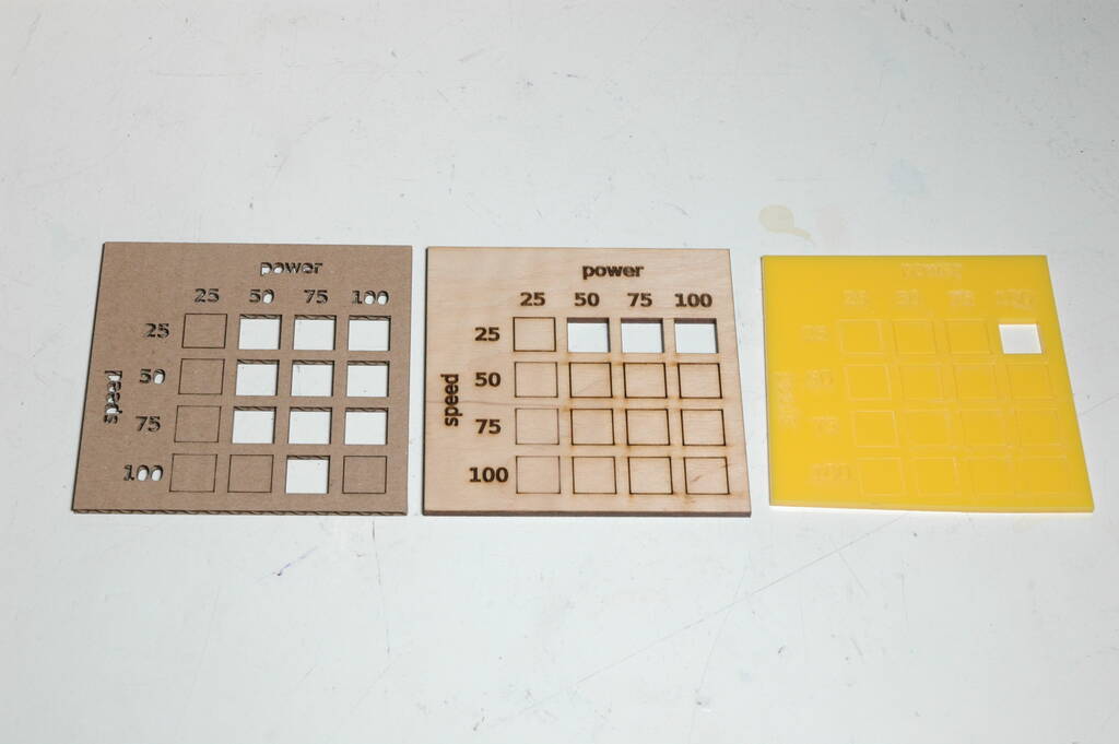
The latter one is only cut with a speed of 25 mm/s and a power of 100%:
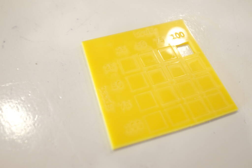
Interesting here was that the plexiglas did not come out straight but somehow warped.
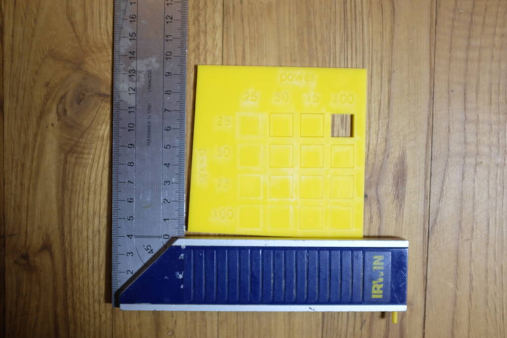
Most likely, the culprit was that the frame around it was too thin and that warped. Michelle and I tried to reproduce this but we could not to the same extent.
Focusing
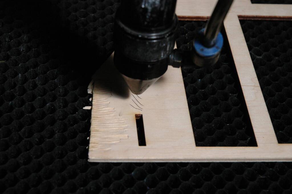
For focusing, I used the following set up with a diagonal cardboard piece where the laser head will move left:
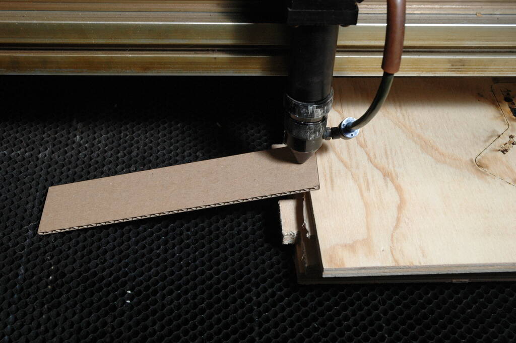
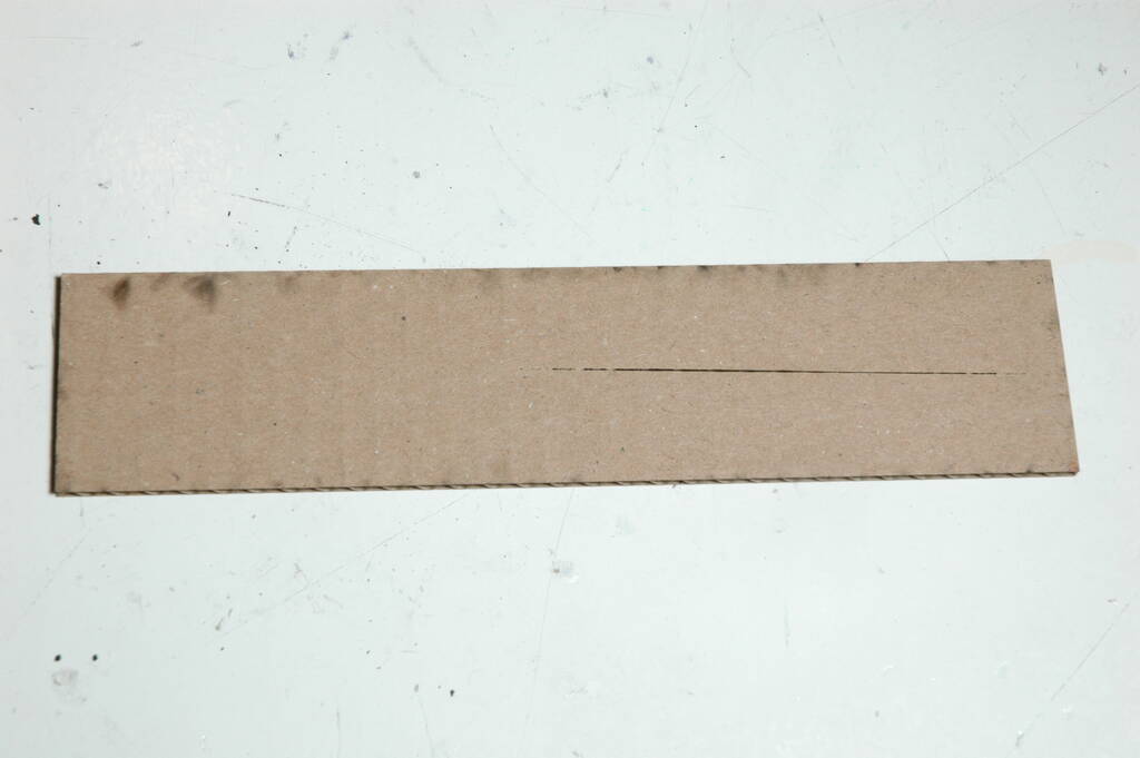
The resulting cut shows that the beam becomes wider when going out of focus, exactly what we would expect:

At the end, the laser still burns some paper, but is unable to cut through it:

The bottom shows where the laser was able to cut the cardboard:
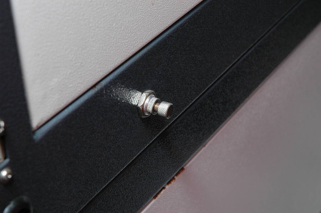
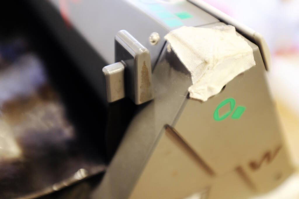
To prevent the cardboard from being blown away, I turned off the air assist in LightBurn, but that didn't work. Henk showed us to turn off the air assist manually on the right side of the machine:
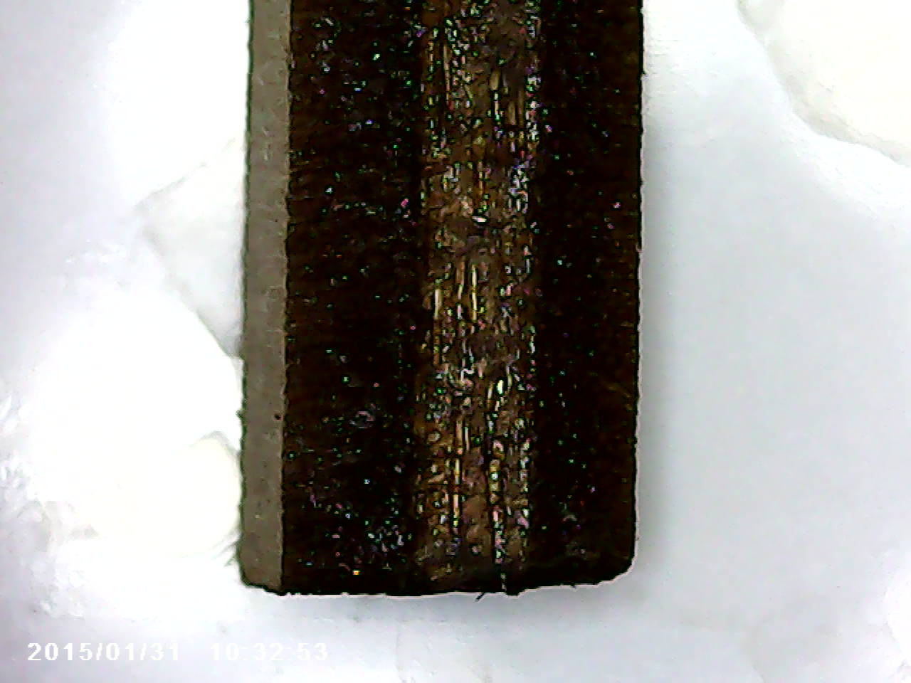
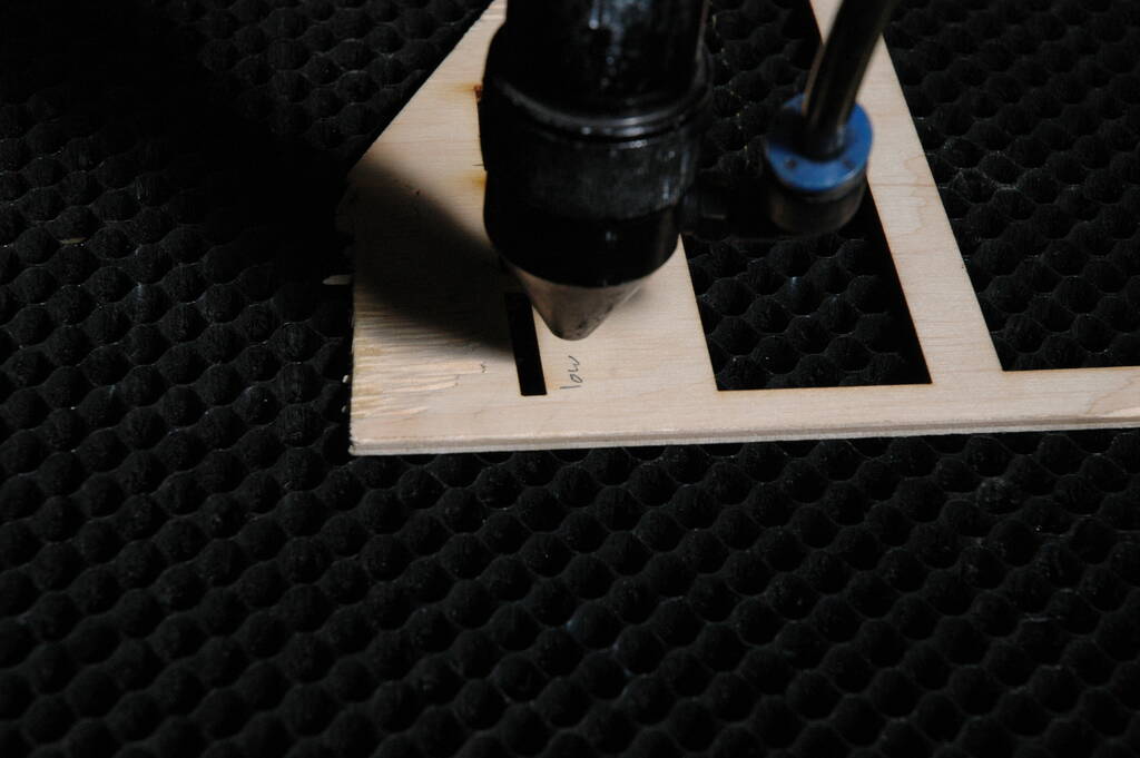
Even in a scenario where the laser beam is perfectly focused, it should not be possible to create a completely 90 degree cut. I investigated this by cutting small pieces of wood 3mm by 20 mm that I will then turn on the side and inspect under a microscope. After inspection, I didn't know what the top side was, so I marked the pieces:
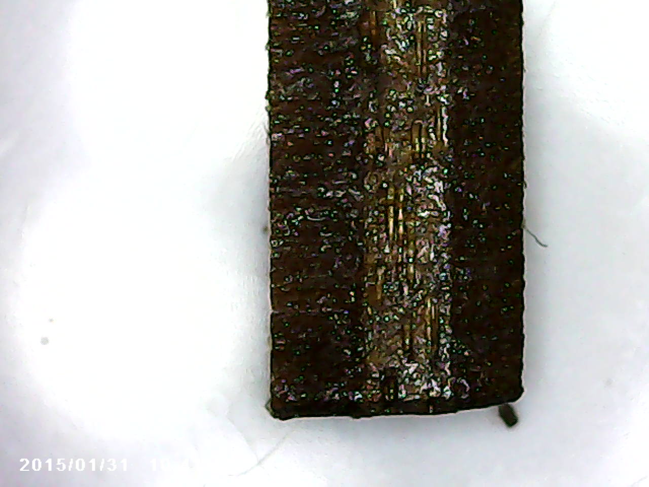
This is the outcome from the microscope and the top side is on the right. It is quite clear that the beam is not straight:
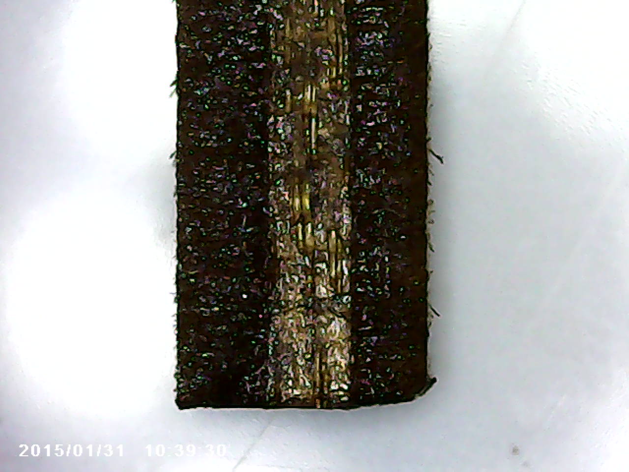
I then marked a piece as low:
And lowered the focus a bit:

The result is equally bad:
Then I marked a piece as high and raised the focus a bit:
This one is the best but it is still not perfectly square. I was ready to conclude that the "focus stick" was not calibrated right, but this was met with suspicion from Henk, who suspected that the material that I used was not completely flat. He was right and after adding some weight to flatten the surface, this is the outcome:
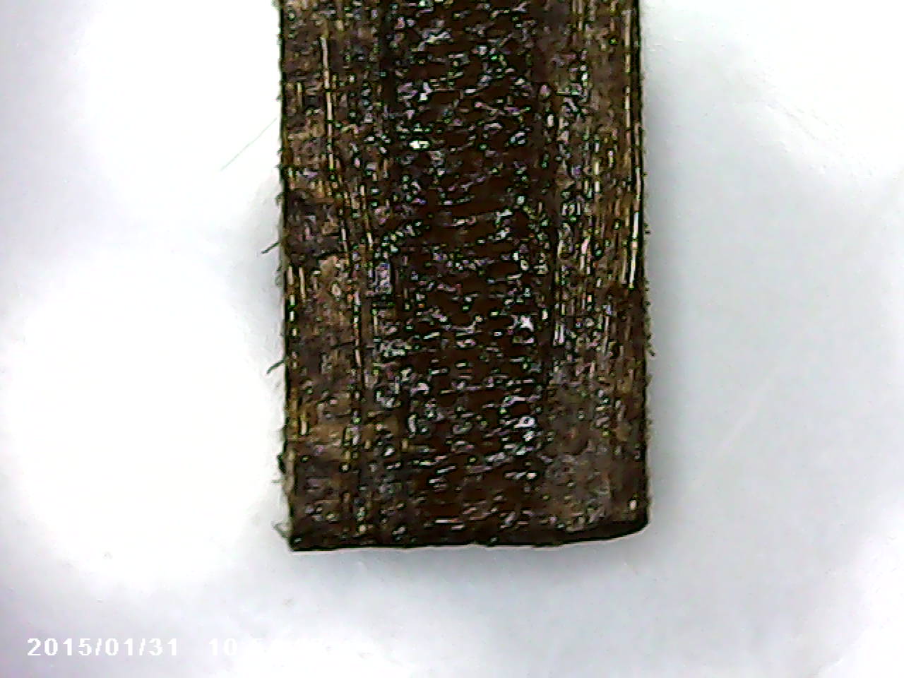
So, we can conclude that focus is important but even with very good focus, the beam is never going to reach a 90 degree cutting edge with respect to the material.
The Vinyl Cutter
Asli gave us an introduction into operating the Vinyl Cutter, a Roland GX-GS24. Vinyl cutters can make precision cuts into various kinds of vinyl, such as stickers and heat-transfer vinyls.
General Overview
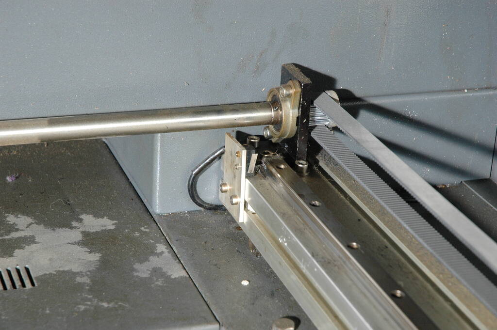
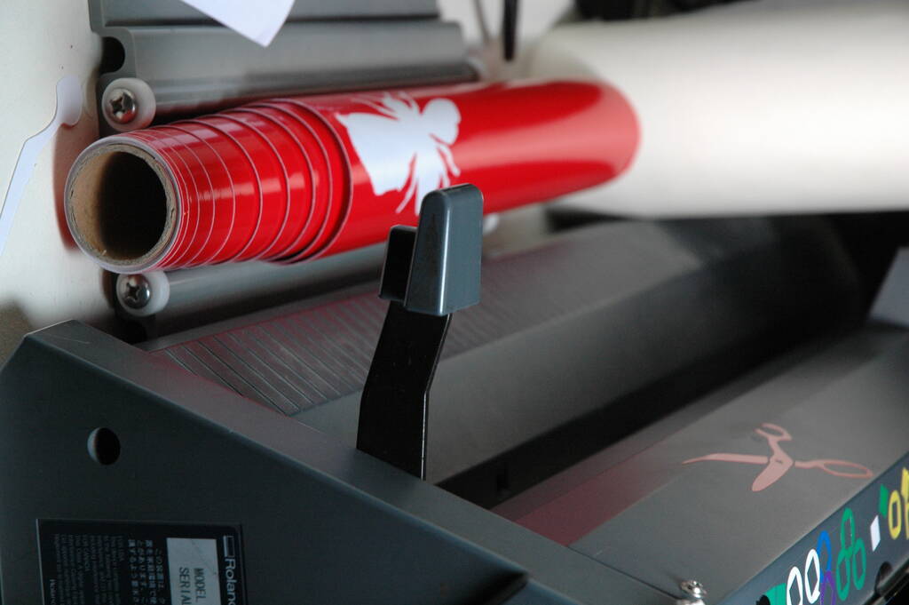
The vinyl cutter can load rolls or sheets and hold different types of tools. A tool that we typically use is a 45 degree 0.254 mm tool. The vinyl cutter can apply different values of force and the cutting tool is loose and turns automatcally based on resistance. The head with the cutting tool on the left side:
A roll loaded:
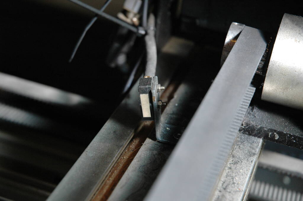
The vinyl cutter has rollers to keep the material down and optical sensors for the edge of the material. A picture of a roller and the sensor:
After something is cut, we need to peel and weed it. Here we have Henk showing peeling:
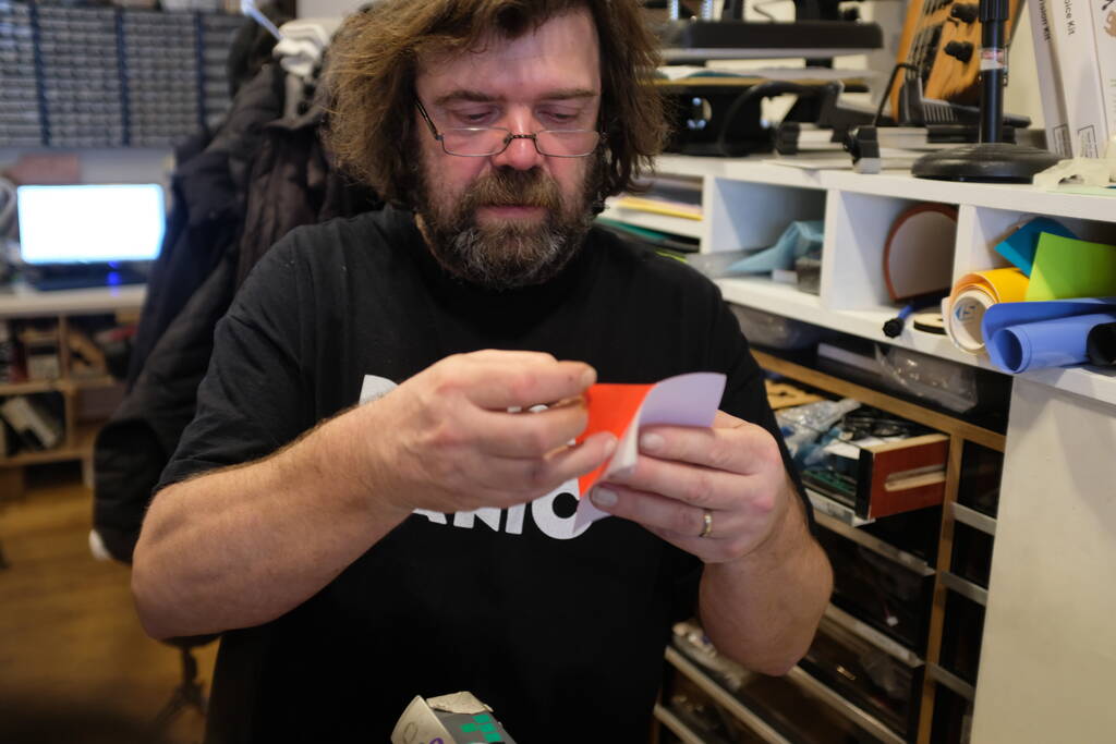
Weeding:

And applying transfer tape to stick the material to the vinyl cutter (yes, we're going meta here).
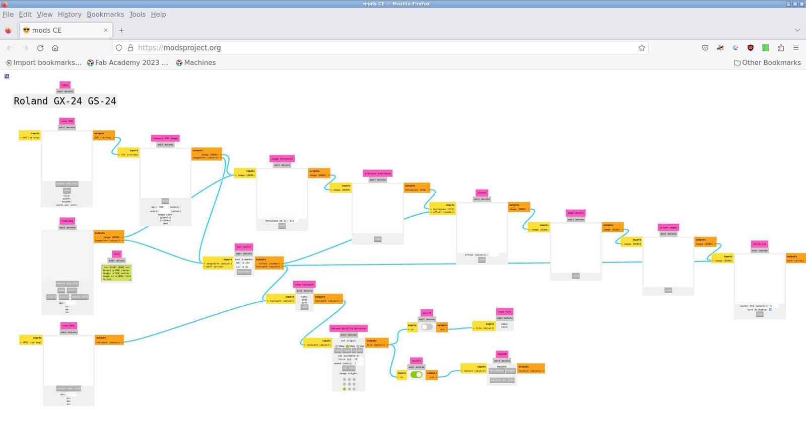
The vinyl cutter is operated from the computer station besides it with the Mods computer program. A screenshot of the program for our vinyl cutter:
Operating the Vinyl Cutter
To operate the vinyl cutter, we have to turn it on and fixate the material which we do with this lever:
The machine will prompt us for the material, sheet or roll:
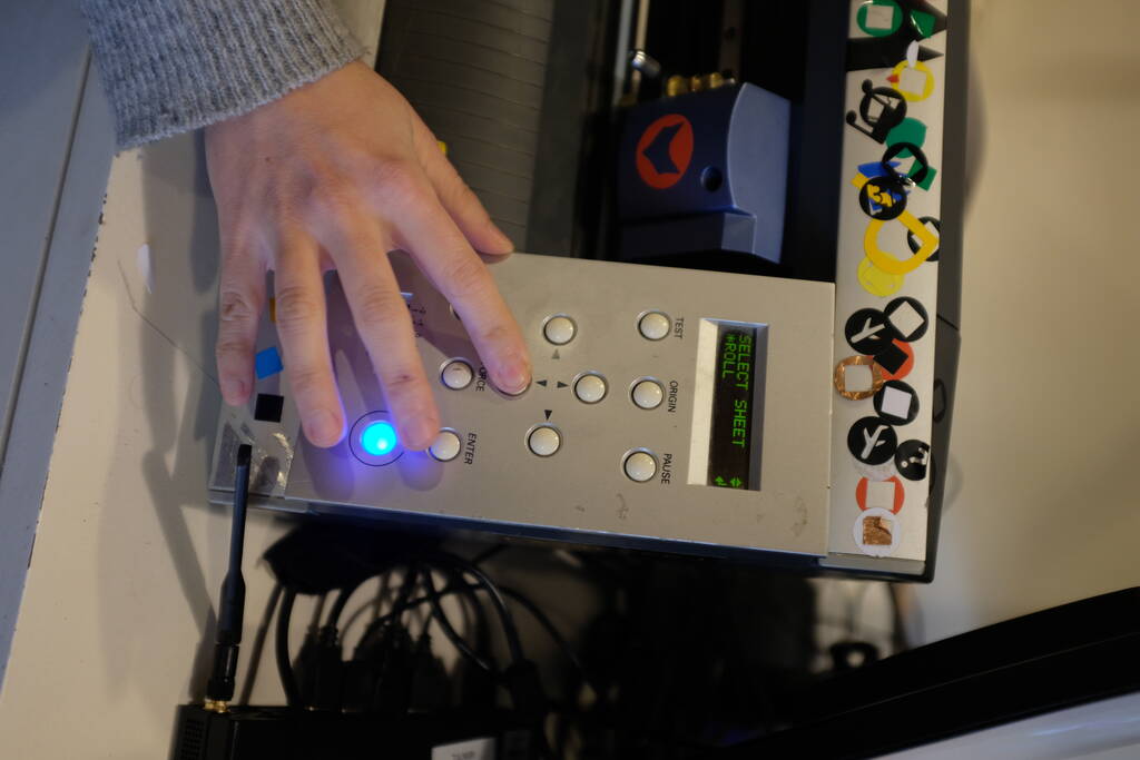
The machine will then find a position to start cutting from. From this moment on, we can operate the machine from the computer.
We open a terminal and type
cd mods
and start up Mods with
bash mods
. It will open a browser that can communicate with serial
ports. In the browser, we right-click to open a menu from which we chose
"programs" and "open program". We then choose
"machines", "Roland", "GX-GS
24 vinyl cutters", and "cut".
This Mods program has inputs for SVG, PNG, and HPGL (Hewlett-Packard Graphics Language) files. Interestingly enough, both the SVG and PNG will be rasterized and revectorized it seems, but the HPGL option seems to not need any conversion, so I believe this is the best choice. Since Inkscape can simply export to HPGL files, this is not posing a problem.
To export from Inkscape, it is necessary to select all objects and convert them to paths ("Ctrl A" to select all objects, and then "Ctrl Shift C" or "Path", "Object to Path" from the menu).
When saving an Inkscape image as HPGL file, Inkscape prompts us with a resolution setting that we can leave as is. For me, the default resolution is 1016 DPI in the X and Y direction and to acquire the same measurements as the Inkscape image has, we need to fill in this value in Mods.
After transferring the image via an USB stick to the vinyl cutter computer terminal, we can load the image from Mods, adjust the resolution to 1016 DPI, check the dimensions, and follow the output edges to "Roland GX/GS-24 Relative" to set the force. A force of 50g is a good initial value.
Then at the bottom right, we can choose "Send file" to start cutting.
Cutting the Open Toolchain Foundation Logo
At Waag we have vinyl rolls green and black or dark blue that look similar to the colors of the Open Toolchain Foundation :
I can first try the green logo and if time permits, I can try to get the black letters, which will be a good exercise in weeding. I can then use this as a laptop sticker!
The Green Logo
In Inkscape, I split the logo file in two parts, one for the green logo and one for the text. Since I was unsure about the resolution setting in the HPGL file and Mods, I carefully inspected the height which was 44.259 mm in Inkscape. I decided that this was a good size for the laptop sticker. I saved the image as an HPGL file on an USB stick to load it onto the vinyl cutter.
I booted the vinyl cutter's computer, opened Mods as described above and loaded the green logo as HPGL file into Mods. Since the resolution didn't match the one Inkscape used, the size was completely wrong but filling in 1016 as resolution made the size similar but not the same, 44.5 instead of 44.259 that I was expecting. This may have to do with the size of the page of the Inkscape image compared to the size of the logo, but I will make a note of this and check this with other jobs. For now, the size is close enough to make it work.
Loading the roll of green vinyl was straightforward, but I was surprised that the vinyl cutter didn't try to find the ends of the material. Asli showed us with a sheet that the vinyl cutter was searching the two ends, but Henk told me that with a roll, it doesn't have to do that.
I chose an initial force of 50 g and after actually sending the file to the machine, the logo was cut in a way I would have expected, but unfortunately, the cut was not deep enough to be able to peel anything.
I set the force to 100 g and sent a cut test and with 200 g, I could peel the material of the cut test. However, when trying to send the logo, the force would be 50 g again, so I couldn't peel it off.
When I consulted Asli, she was surprised that I needed that much pressure and she noticed that the tool was not fixated in the head. I didn't check this an simply assumed that the tool was properly installed. This is a tool properly installed:
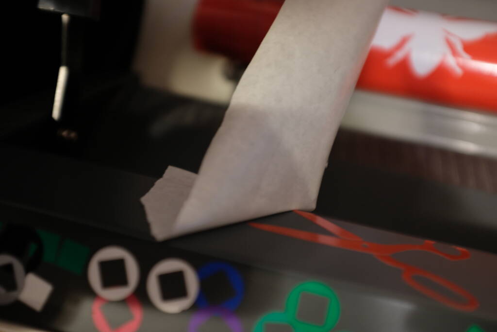
After fixating the tool and retrying with a force of 50 g, the cut came out well, first cutting around the logo with a pair of scissors:
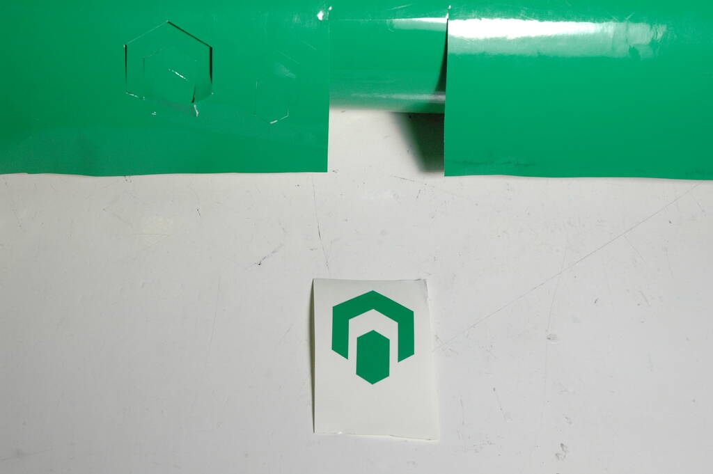
Then peeling off material around the logo. This is ready to be put on transfer tape besides the text.
The text
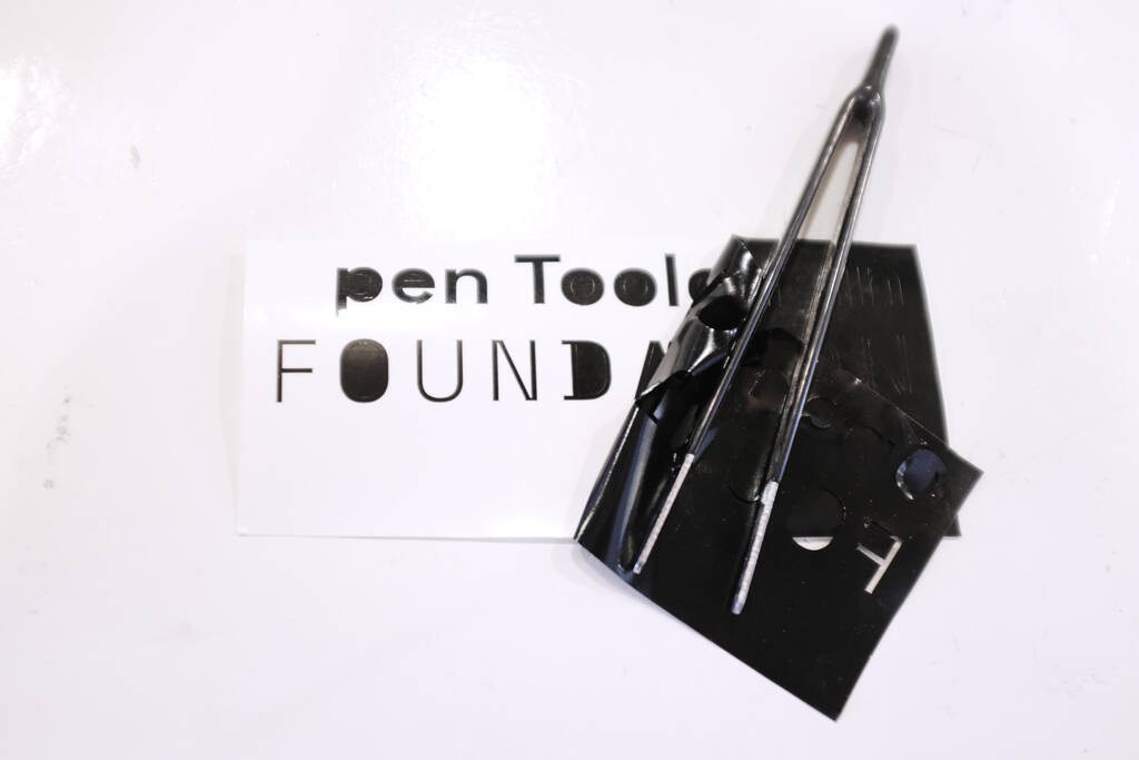
Cutting the text on a black roll was straightforward after the experience with the green logo. Weeding proved to be quite difficult. I used the following pair of tweezers.
Initially, the weeding went well until I came across the O, the first letter that was cut. It seemed as if the vinyl cutter cut through the O and I thought that I could see this when holding the residu material against the light. Henk disagreed and said it was more likely that I applied the tweezers wrong and that the faint line that was visible. It was difficult to photograph this and I simply have to try again, because we couldn't salvage the O. I can still practice my weeding skills though.
I remember that when the cut started I saw a jerking movement from the vinyl cutter, similar to what we've seen with Asli's demo. Perhaps this was a factor. I will try this again and inspect the cut of this particular letter before I start weeding.
In any case, Henk advised me to use finer tweezers.
Reflections
Mods has a couple of annoying things: With every keystroke when adjusting the resolution of the file, it opens a viewer with the image that has to be closed before you can enter another character. After sending a file to the vinyl cutter, it is not possible to resend the same file again, you have to make Mods believe you opened another file. Initially, I refreshed the browser, but Asli told me that I can simply make a small adjustment to the resolution to have Mods believe that a new file is loaded.
A Cardboard Construction Set for Model Cars
In this section, we discuss the design and cutting of a construction set for a track for 1:64 scale model cars. The main idea is we have a different track pieces with rails that we can connect to create a track for the model cars. The idea is inspired by the infinite interest in cars that my two year old son has. He will definitely like the track very much and will most likely destroy it within one minute.
Design Philosophy
I copied the initial measurements from an existing track system: the width of the track is 34 mm, the length of a track piece is 350 mm and the height of the rails is 6 mm. The track piece will contain pins to attach the rails to the side. The rails will protrude 6 mm but it will also extend beneath the track having two functions: connecting track pieces to each other and attach to pillars that can have various sizes and widths for stability.
This stability is necessary because cardboard is much lighter than the cars that drive on them, so to make the structure stable at a height, we may need to have wide pillars. I aim to make the structure of the pillars such, that I am flexible in building pillars.
The track pieces that I have in mind are: a straight one, a curved one (if way of connecting two pieces is symmetrical, it can go both left and right), a sloped one with flexures, and a curved sloped one with flexures. This allows for spiral development and let's see how far I will get.
Thickness Measurements
I wanted to have chamfered connections between the cardboard, so I decided to make my own chamfered comb as well to measure the right thickness of the cardboard.
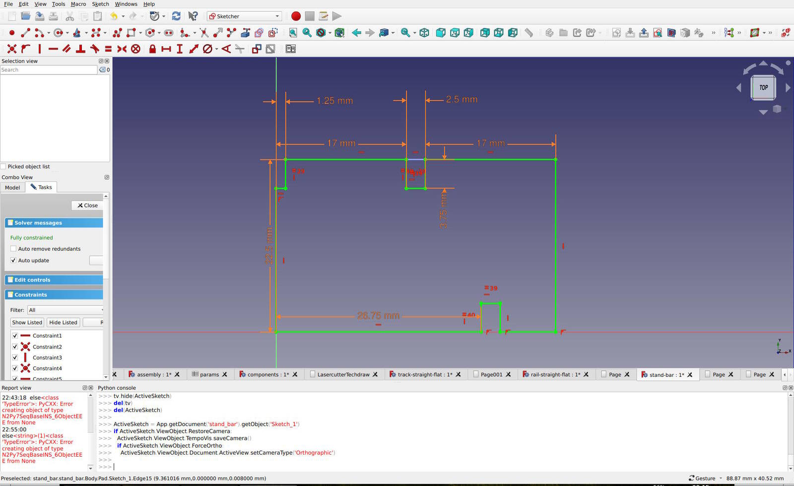
The design of the chamfered comb is done in Part Design in FreeCAD, but I don't think this is the right tool because of all the repetitive constraints. It would probably be much easier to code a design like this. In principle, this is possible in FreeCAD, but it is a bit awkward. Perhaps I should try again with CadQuery some time. I would love to have feedback on how to do this properly in FreeCAD. Perhaps I should post this on the FreeCAD Forum.
The screenshot below shows the fully constrained comb in the Sketcher workbench:
I investigated various ways to export this to an SVG to laser cut. The easiest option is to simply use a technical drawing that can be saved as an SVG. The Path workbench is designed for controlling CNC machines, but it seems to be more focused to milling than to laser cutting. The best option that I came across was the macro "LasercutterSVGExport" that can be installed with the Addon Manager (Tools, Addon Manager, Macros). This allows you to set the laser beam width (for which I choose 0.20 mm, roughly corresponding to Michelle's measurement).
This gave me the following SVG that takes into account the kerf:

In Inkscape I added the text to engrave, because I didn't have time to figure out how to do that in FreeCAD. This is something that I would like to find out, though.

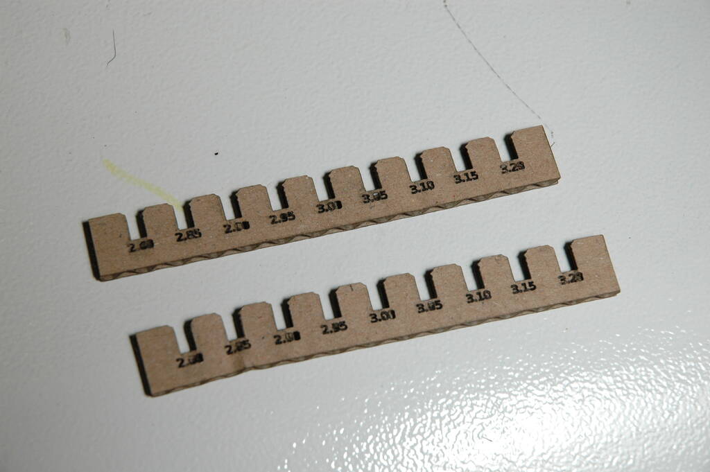
The resulting laser cut piece is:
Reflections
My initial design had a depth of 6 mm for a pin and the "body" had a height of 6 mm as well. This proved to be not strong enough to do proper thickness measurements because the "body" bends far too easily, as can be seen in the bottom left with 2.85 mm:
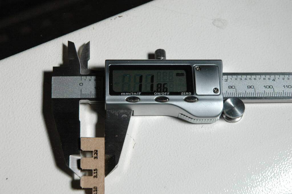
I also measured the height of the comb to check how good the SVG export macro took account the kerf. I measured 11.86 mm which should have been 12 mm. Good enough in my view for such a short distance.
Designing the track
Designing the track pieces was very difficult and at first I didn't know how to approach this properly. I wanted to add chamfering, but this complicates the sketches. For the track piece, I wanted to add pins, but how could I best approach this? I could think of several options:
- Design the track piece as a simple rectangle, design a pin, and place the pins at the positions where I want the pins. This sounds viable, but placing the pins is lots of repetition.
- Sketch the track piece and "add" other sketches: This sounds like a good approach, but I simply don't know how to do this.
- Sketch the whole track piece "manually" adding all the pins: This is lots of work and very repetitive.
- Make the design as symmetric as possible and exploit symmetry. This sounded the most elegant solution to me and this is what I followed.

The width of a pin is 6 mm and the depth is the thickness of the card board. Mirroring this along both the X and Y axis gives the following track piece with 3 pins on either side:
This has been achieved by padding the sketch to the thickness of the card board and apply a multi transform (Part Design, Apply a Pattern, Create MultiTransform), with mirroring along the horizontal and along the vertical axis.
Designing the rails
Since the track piece was designed with symmetry in mind, I can again exploit symmetry for the rail, albeit only on the vertical axis:

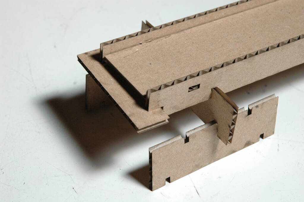
The rail has holes for the pins. Because the design is fully parametric and I exploit symmetry, the holes are at the right location. The rail has a horizontal slot on both ends. This serves the purpose of connecting the track pieces which will become more clear below. The bottom slots are for attaching the pillar construction beneath the track pieces.
Designing the pillars
I wanted to have a construction set of bars or beams to create pillars such that I could make them both wider and higher. Higher to support sloped track pieces and wider to resist the forces in high track pieces with corners.
I came up with these simple bars that I can connect cross-wise to create "pillars":

Assembly Workbench
To verify the designs of these three basic parts, I used the Assembly 4 Workbench to create an assembly:

The Assembly 4 Workbench is a bit different than regular solver-based assemblies, but it is a very interesting approach in my opinion. For a part, it allows one to place a local coordinate system at "connecting points". Assembling pieces together is then based on connecting the local coordinate systems.
Reflections
I noticed something interesting in designing. Last week, I received the comment that I used too many parameters. I'm aware of the fact that it is best to design with as few design parameters as possible and base the design on these few parameters and make as much as possible use of constraining based on equality or symmetry.
However, while adopting this approach, I noticed later on in the assembly process that I required the distance of a slot from the origin to be able to place the part properly in the assembly. However, there was no existing variable that had this value because the position of the slot was based on symmetry. Therefore, I needed to calculate the distance of the origin anyway while it was not in my design. Let's make this concrete:
This is the sketch that contains the measurement 26.75 mm at the bottom. This is the distance from the origin to the slot at the bottom right.
All the orange measurements are based on parameters in the design and the
name of the parameter of 26.75 mm is
distance_stand_connection_bottom
. Having this value in a
parameter, allows me to use this parameter to place a local coordinate
system at this location. Conventionally, local coordinate systems are
matched with edges in the sketch, but I don't like to use this approach
because I consider edges and their names not stable enough to base
features on. So, I always prefer to base features on fixed points such
as the origin, Y, X, or Z axes. For that reason, it is good for me to
know the distance of the slot to the origin and have this in a variable.
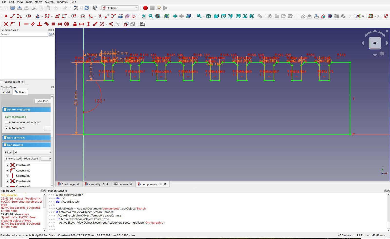
Let's compare this with the sketch I had before, not making use of fixed distances, but by exploiting symmetry:
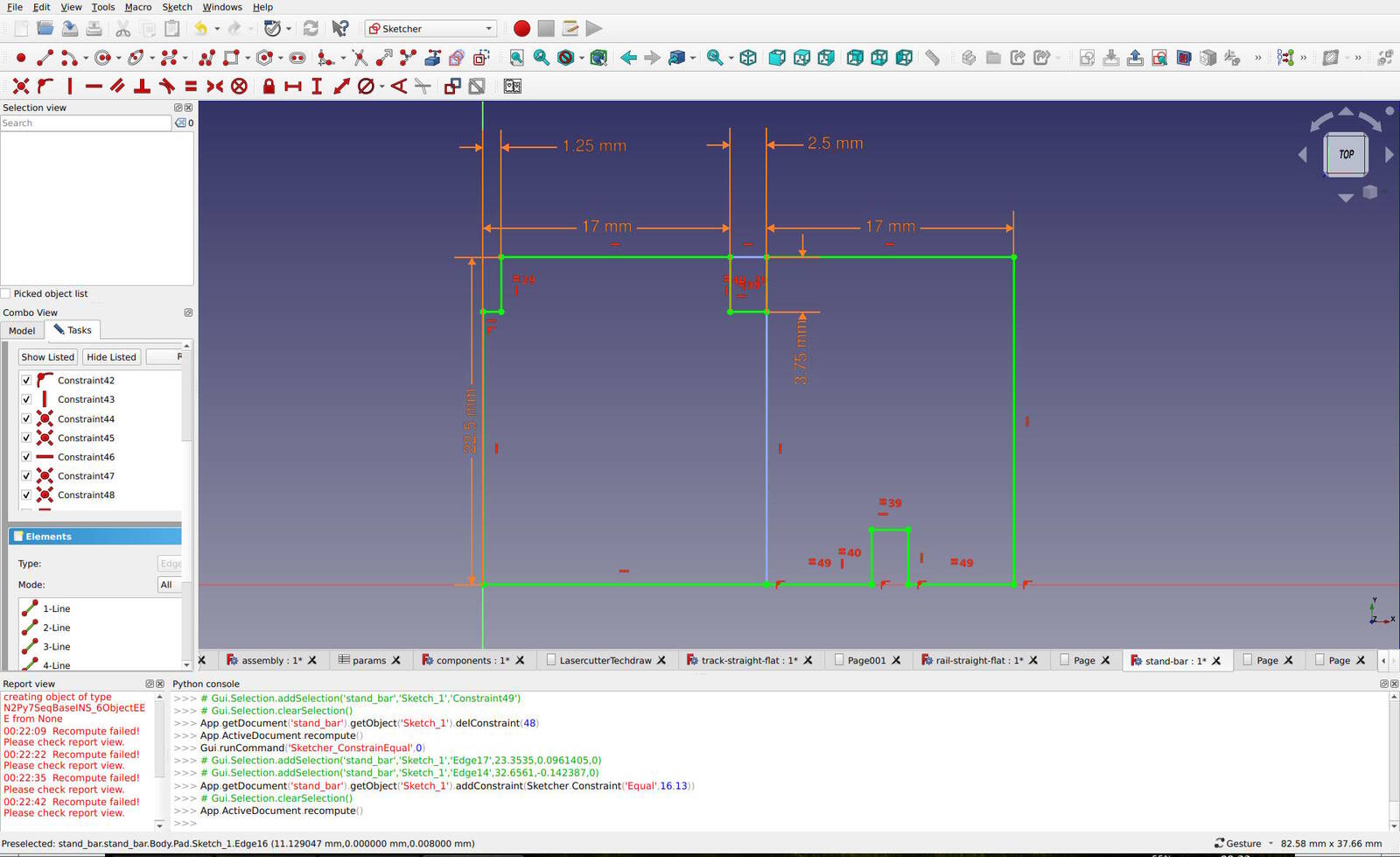
Instead of explicitly contstraining the distance, I drew a reference line
down and constraint the edges leading to the lower-right slot to be equal
(the
=49
constraint). This is the exact same design but the
symmetry is expressed in an equality constraint instead of a formula.
This is arguably more elegant, but it prevents me to use the distance to
the slot from origin in other parts of the design.
This raises the question whether the values I use in the spreadsheet are actually parameters. I think I use "parameters" more as "variables" to express the dimensions. The real parameters of this design are the thickness of the cardboard, the width and length of a track piece and perhaps the height of rails. The rest is simply a set of variables that I use to express the design.
Acquiring SVGs from FreeCAD
Acquiring SVGs to feed to the laser cutter was a very frustrating and time intensive experience. The comb I cut earlier was no problem but the pieces I designed for the track were based on symmetry. No matter, which option I tried, all SVG exports featured the seam line between the mirrored images (the same can be seen in the images above). This is not what I should feed to the laser cutter because it would simply cut the pieces in half.
The LasercutterSVGExport macro makes use of the Technical Drawing workbench. It has settings to get rid of seam lines and other kinds of lines, but none of these settings had an effect. Essentially, I only want the outline lines. Using the Technical Drawing workbench was an option as well, but as expected, I had the same lack of control.
Another option was the Path Workbench where I tried several options. However, it seems to export to GCode directly where I wanted to have a simple SVG. DXF was an option, but the number of options that the Path Workbench provides were overwhelming anyway, so I decided to not use it.
The Draft Workbench has the Shape2DView functionality that projects an image, but also with these functions, I still got the seam lines. I went back and forth over all these options, each time trying something new and going a bit deeper into the workbench, each time concluding that it was not working and I had better try another option.
In the end, I found out how to get rid of the seam lines. I think I found this out because I vaguely remembered that this was an option. While digging long enough, I eventually found out that the Part Workbench has the functionality to refine shapes (Part, Create a copy, Refine shape). This would create a copy with the seam lines removed. I could use this then with the LasercutterSVGExport macro to create a nice SVG for the laser cutter.
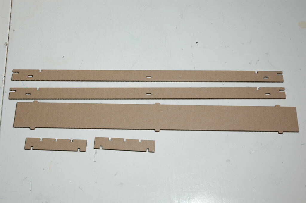
Laser Cutting the Pieces
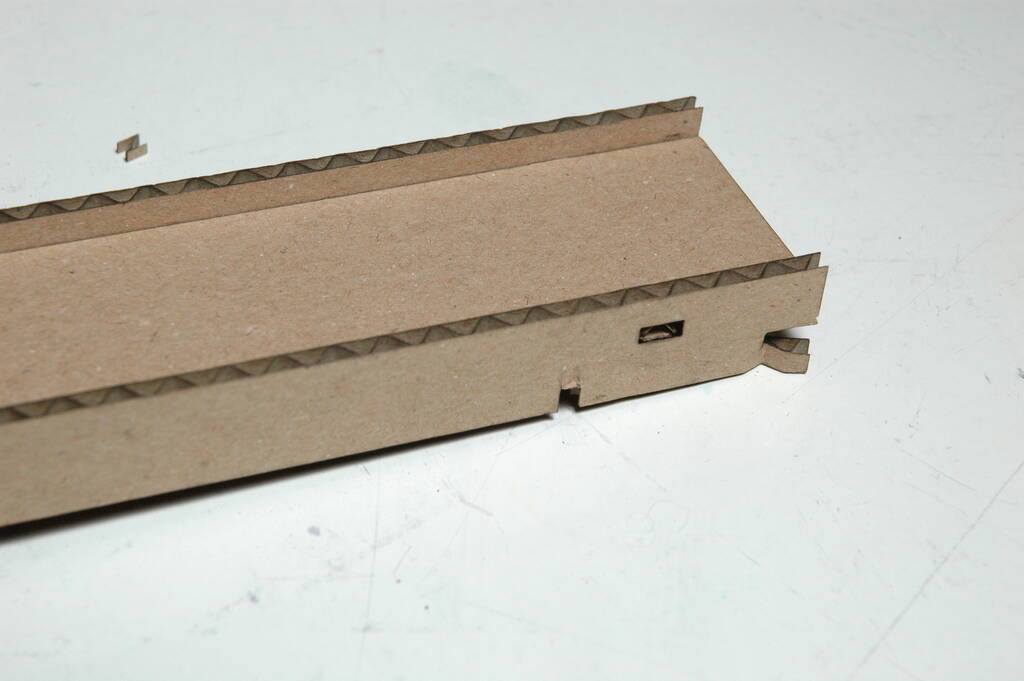
After having proper SVGs, cutting the pieces was straightforward and the first try came out like this:
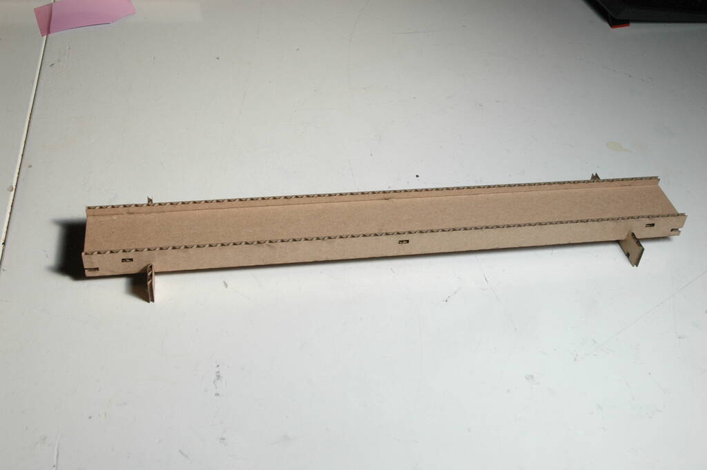
Assembled:
More pieces with higher bars for the pillars:

Assembled:

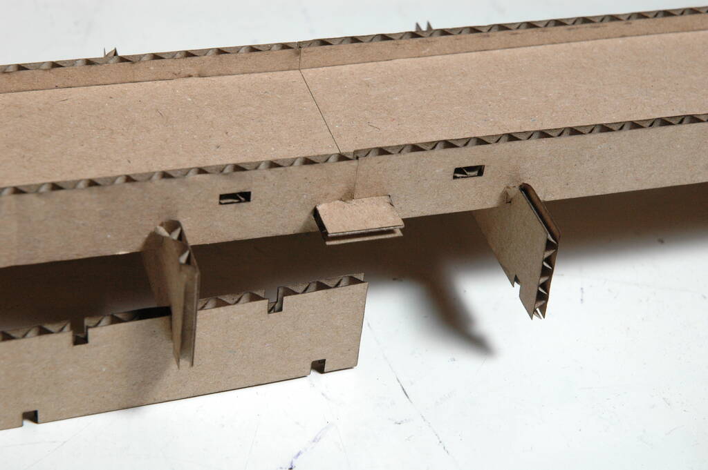
Connecting two track pieces:
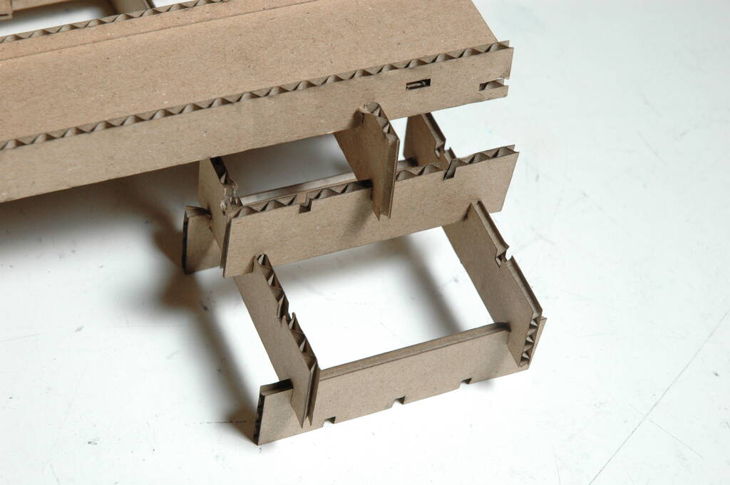
The "pillar" made out of bars:
A higher and wider configuration of the bars for a pillar:
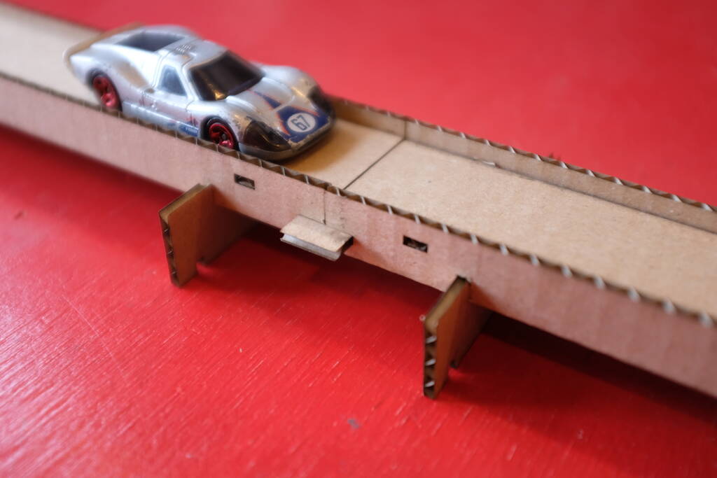
And a car driving on it:
Reflections
The design is not fully satisfying my needs. The bottom of the rails is to thin, making the cardboard bend easily.
The bars for the pillars could be tweaked in size to prevent them bumping into each other. This is especially a problem with the two close-by pillars of two connecting track pieces.
Finally, unfortunately, I only have straight track pieces. However, I hope to show the generality of the approach and that it is actually a construction kit.
Tasks
Fab Academy
- Characterize your laser cutter's focus, power, speed, rate, kerf, and joint clearance.
- Design, lasercut, and document a parametric press-fit construction kit that can be assembled in multiple ways. Account for the laser cutter kerf.
- Demonstrate and describe parametric 2D modelling processes.
- Identify and explain processes involved in using the laser cutter.
- Cut something on the vinyl cutter.
- Include the original design files.
- Include hero shots of the results.
Personal
- Make a bended track piece.
- Make a track piece that goes down with flexures.
- Cut the text of the Open Toolchain Foundation logo properly.