Project Management
For this week, I'm going to try spiral development again to make sure that I cover as much as possible of the above requirements. Instead of modeling all the components of the final project, I will focus first on modeling the outside of the final project and then trying to render, animate, and simulate that. If time permits, I can reiterate on that adding more details to the model.
Tasks
The following tasks are expected:
- model a possible final project,
- evaluate and select 2D and 3D software,
- describe the processes with words/screenshots,
- compress images/video and post it, and
- include the original design files.
I want to try to include a 3D rendering of the final project on my website in such a manner that you can manipulate it. So, the user should be able to rotate and zoom out.
Reflections
This was a good approach. Modeling the outside was already challenging as I've never modeled something that I initially drew by hand. The fact that the final project was sketched by hand resulted in a design with much more roundings than I would designed starting out with a CAD program.
If I would have focused on modeling all components, I would have never had time to investigate the rendering.
Evaluating and selecting 2D and 3D software
Since I only want to use Open Source Software, the choices are limited. For 2D I'm already quite familiar with Inkscape and for 3D I'm familiar with OpenSCAD and FreeCAD. I prefer coded CAD because it allows you to review changes in Git so well, but OpenSCAD is based on CGAL that is based on meshes which limits the precision in CAD models. An alternative coded CAD that is based on boundary representation is CadQuery but I have no experience with this whatsoever. Since FreeCAD is based on BREP and the current design will already push my knowledge of FreeCAD, I decided to use FreeCAD.
For drawing precisely, I prefer not to work with raster images. Although Inkscape is very powerful, I often have problems with being precise in Inkscape. This may not matter for figures on paper or screen but for geometry for physical artifacts, I prefer more precise drawing. FreeCAD's Sketcher workbench gives me these possibities with powerful constraints that allow you to be very precise.
For rendering, I would like to become familiar with Blender. I know it is a powerful tool but I have never worked with it. I know that there is good exchange between FreeCAD and Blender.
Modeling the Final Project
I would like to get close to what I have drawn and as said above, I will first focus on the outer body. It is a conscious choice not to think about whether machining/printing such a design is possible, simply because I have not enough experience with fabrication techniques. So, for now, I simply model what I drew and I will adjust later if it turns out that it is impossible to make.
Design Rationale
The drawn outer shell is round at the base, but elliptical at the top. Somehow they should "connect", so I believe I require a loft for that, although I'm not sure.
The outer shell is round at the bottom to give the device stability when my head rests on it. Since my eyes form the only part that should be heated, the top part is elliptical. Inbetween the part where my face rests and the bottom, there is something that I will call a neck that tapers out for a comfortable fit for my head.
So, some terminology: we have the round base , there is the neck that supports the elliptical face part , the part where my head will rest.
Approach
I will approach the design by using master sketches in 2D. In this case, a series of top-down master sketches and a front master sketch will provide enough information to understand the design in 3D.
In addition to the master sketches, the design will be fully parametric since I do not know what good sizes are and how large several components will be.
Parameters
I first started defining the parameters of the base, face part, and neck.
I created a separate
params.FCstd
with a spreadsheet called
"params". This allows me to quickly choose parameters in expressions
and a
separate file allows to reuse various parameters for different components.
| Parameter | Value |
|---|---|
| width_base | 100 mm |
| width_face_part | 100 mm |
| depth_face_part | 50 mm |
| height | 200 mm |
| height_neck | 180 mm |
| width_neck | 80 mm |
| depth_neck | 50 mm |
Master Sketches
The master sketches are drawn in the Part Design workbench and the three top master sketches (with a top view) only consists of circles and ellipses:

All geometry is fully constrained with the middle point on the origin using the dimensions listed above. The ellipses are constrained to be fixated to the X-axis to prevent rotation.
The front view master sketch shows the outline on one side. This sketch was created by allowing the external geometry of the circle and two ellipses to be used as anchor points, allowing me to draw the two straight lines connecting the top ellipses. The front view also shows that the two ellipses have been placed at the correct height. This is done by means editing the Z value of the Position of the Attachment property of the Sketch.

The following image provides a bird's eye view to better understand the front and top master sketches.

The outside body can now hopefully be created by applying a "loft".
Applying Loft
This required much experimentation and my limited knowledge was the culprit. I would assume that I needed to loft over both the base and the two ellipses, but this resulted in the following:

It looks nice, but it won't have room for the logic. I assumed that the neck would have a separation from the base and the face part. What was required was to apply two lofts: the neck to the base, and the neck to the face-part ellipse:

Notice that the two lines of the front view master sketch are also drawn, to show that this design follows the outline I had in mind. The parameters of this version have been slightly changed compared to the images above.
Cutting out the inside
The above images only a solid, but there should be a basin and heating elements inside, so let's use the "Cut" boolean operation to cut out an inside. Since I am not modeling the other components as of yet, I decided that I simply make a cutout such that the outer shell has the same thickness everywhere.
Unfortunately, my FreeCAD version doesn't have an offset tool in Sketcher,
so effectively, I drew the same geometry again with formulas such as
width_base - 2 * thickness_body
. I then apply the boolean operation
"Cut" to achieve the following:

Cutting out the Nose
Cutting out the nose boiled down to drawing a half circle. This was done
on the XZ plane and then with the Attachment feature of the sketch, I
wanted to place at the height of parameter
height
. I expected to
need to change the Z value of Position, but instead I needed to change the
Y value. It puzzles me why changing the Z value brings the sketch forward,
along the Y axis, whereas changing the Y value brings the sketch up along
the Z axis.
After placing the nose sketch at the right position, I could simply extrude it and use a boolean operation to cut this out of the main body. The resulting geometry is:

Mimicking the drawn dimensions
To find an approximation of the dimensions that I drew by hand last week, I loaded the image in the Image workbench on the XZ plane and scaled the image such that it approximated the dimensions that I had modeled. Since the drawn image uses a different perspective than a full front-view, I tilted the image pane such that when looking at the 3D model from slightly above, it matched the drawing. The following screenshot from FreeCAD shows the tilt of the image to match the perspective from the front. Making the 3D model transparent allows me to adjust the dimensions of FreeCAD.
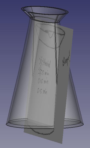
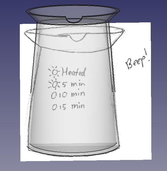
The front view looks like this. You can see that I tried to tilt the image pane to the direction of the camera where the camera is positioned such that it mimicks the perspective on the hand-drawn image:
Dimensioning the design to match the hand-drawn sketch, the model looks like this:
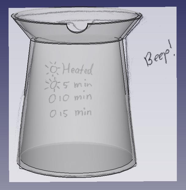
The resulting model:

The parameters to achieve this are:
| Parameter | Value |
|---|---|
| width_base | 170 mm |
| width_face_part | 185 mm |
| depth_face_part | 90 mm |
| height | 215 mm |
| height_neck | 180 mm |
| width_neck | 130 mm |
| depth_neck | 50 mm |
| thickness_body | 5 mm |
| width_nose | 30 mm |
I received the comments that these parameters seem many. However, I want to stress that all parameters are used to mimick the hand-drawn dimensions. I think that in mechanical design it is logical to use as few parameters as possible, but in this case, the design is based on a hand-drawn sketch. In that case, it is good to have the flexibility to be able to adjust.
Reflections
I lost much time with not properly understanding loft. In hindsight it is very logical that the operation I had in mind would not work, but I guess I had a bit of tunnel vision there.
While changing the dimension, I found a bug in the parameters: The width of the ellipse of the face part had been set to the width of the base, so the design was broken. It was very clear that a parameter was wrong and after locating the right expression, it was obvious that the expression was wrong.
Exporting the Model for Website Inclusion
One of my goals is to include the model into the website, such that it can be viewed from all angles by a user. I often notice rendered images of 3D models, but I would like to have a wire frame with hidden lines because that is the most useful in manuals in my view.
FreeCAD can simply export a
glTF
model from a body. This results in a
.gltf
and a
.bin
file.
From a website, the
.gltf
file has to be loaded and the bin file
should be in the same directory as well.
For actually viewing it on a website, we need a glTF viewer. A common one is Three.js . I want to set this up such that all faces are white without shading and the lines are black, so a wireframe but with hidden lines. This proved to be difficult to achieve and in the end I haven't succeeded.
Setting up ThreeJS
First, I followed the tutorial
Loading an .OBJ file
. It
had an introduction into Blender as well, but I couldn't access the
original Blender files. However, I copied the resulting
.obj
file
and tried to make
this
example work
locally. I don't want to load outside Javascript because of
unclear licensing, so I commented out the following:
<!-- <script async src="https://unpkg.com/es-module-shims@1.3.6/dist/es-module-shims.js"></script> -->
Because of this, I needed to load the Javascript files locally and this turned out to require absolute paths, so prefixing them with the current directory:
<script type="importmap">
{
  "imports": {
    "three": "./js/three.module.js",
    "three/addons/": "./js/"
  }
}
</script>
The next step was to load an
.obj
file. After exporting my model
from FreeCAD as an
.obj
file, I needed to change various settings to
make it visible:
- the rotation,
- what far and near means for the rendering,
- the camera position,
- the size of the plane, and
- the rotation of the object.
diff --git a/index.html b/index.html
index a501c3f..e32bc0c 100644
--- a/index.html
+++ b/index.html
@@ -45,10 +45,10 @@ function main() {

   const fov = 45;
   const aspect = 2;  // the canvas default
-  const near = 0.1;
-  const far = 100;
+  const near = 1;
+  const far = 1000;
   const camera = new THREE.PerspectiveCamera(fov, aspect, near, far);
-  camera.position.set(0, 10, 20);
+  camera.position.set(500, 500, 500);

   const controls = new OrbitControls(camera, canvas);
   controls.target.set(0, 5, 0);
@@ -58,7 +58,7 @@ function main() {
   scene.background = new THREE.Color('black');

   {
-    const planeSize = 40;
+    const planeSize = 400;

     const loader = new THREE.TextureLoader();
     const texture = loader.load('resources/images/checker.png');
@@ -99,7 +99,8 @@ function main() {

   {
     const objLoader = new OBJLoader();
-    objLoader.load('resources/models/windmill/windmill.obj', (root) => {
+    objLoader.load('resources/models/main-body-outside.obj', (root) => {
+      root.rotation.x = Math.PI * -.5;
       scene.add(root);
     });
   }
Loading a glTF from FreeCAD was trivial by using the module
GLTFLoader
instead of
OBJLoader
. Again, to make this work, it required changing
parameters in a similar way as above.
The required Javascript is:
function main() {
  // render to HTML element <canvas id="c">
  const canvas = document.querySelector('#c');
  const renderer = new THREE.WebGLRenderer({canvas});
  renderer.outputEncoding = THREE.sRGBEncoding;

  // field of view, what is near or far
  const fov = 45;
  const near = 0.1;
  const far = 100;
  const camera = new THREE.PerspectiveCamera(fov, window.innerWidth / window.innerHeight, near, far);

  // position depends on the size of the object
  camera.position.set(0.0, -0.3, 0.3);
  const controls = new OrbitControls(camera, canvas);
  // the camera initially looks up a bit
  controls.target.set(0, 0, 0.1);
  controls.update();

  // set up the scene
  const scene = new THREE.Scene();
  scene.background = new THREE.Color('white');

  // for understanding where the axes are
  // const axesHelper = new THREE.AxesHelper(1);
  // scene.add(axesHelper);

  // set up the light
  const color = 0xFFFFFF;
  const intensity = 3;
  const light = new THREE.DirectionalLight(color, intensity);
  light.position.set(1, -0.5, 1);
  light.target.position.set(0, 0, 0);
  scene.add(light);
  scene.add(light.target);

  // load the glTF file
  const gltfLoader = new GLTFLoader();
  const url = 'models/main-body-outside.gltf';
  gltfLoader.load(url, (gltf) => {
    const root = gltf.scene;
    // rotate it to have FreeCAD and ThreeJS agree on the axes
    root.rotation.x = Math.PI * .5;

    scene.add(root);
  });

  // resize dynamically
  function resizeRendererToDisplaySize(renderer) {
    const canvas = renderer.domElement;
    const width = canvas.clientWidth;
    const height = canvas.clientHeight;
    const needResize = canvas.width !== width || canvas.height !== height;
    if (needResize) {
      renderer.setSize(width, height, false);
    }
    return needResize;
  }

  // do the rendering
  function render() {
    if (resizeRendererToDisplaySize(renderer)) {
      const canvas = renderer.domElement;
      camera.aspect = canvas.clientWidth / canvas.clientHeight;
      camera.updateProjectionMatrix();
    }

    renderer.render(scene, camera);

    requestAnimationFrame(render);
  }

  requestAnimationFrame(render);
}

main();
Rendering Lines
After many searches for both Blender rendering and glTF rendering, I found a way to find all Mesh objects using this function:
function logObjects(object) {
  object.children.forEach((child) => {
    console.log(child);
    logObjects(child);
  });
}

const root = gltf.scene
logObjects(root);
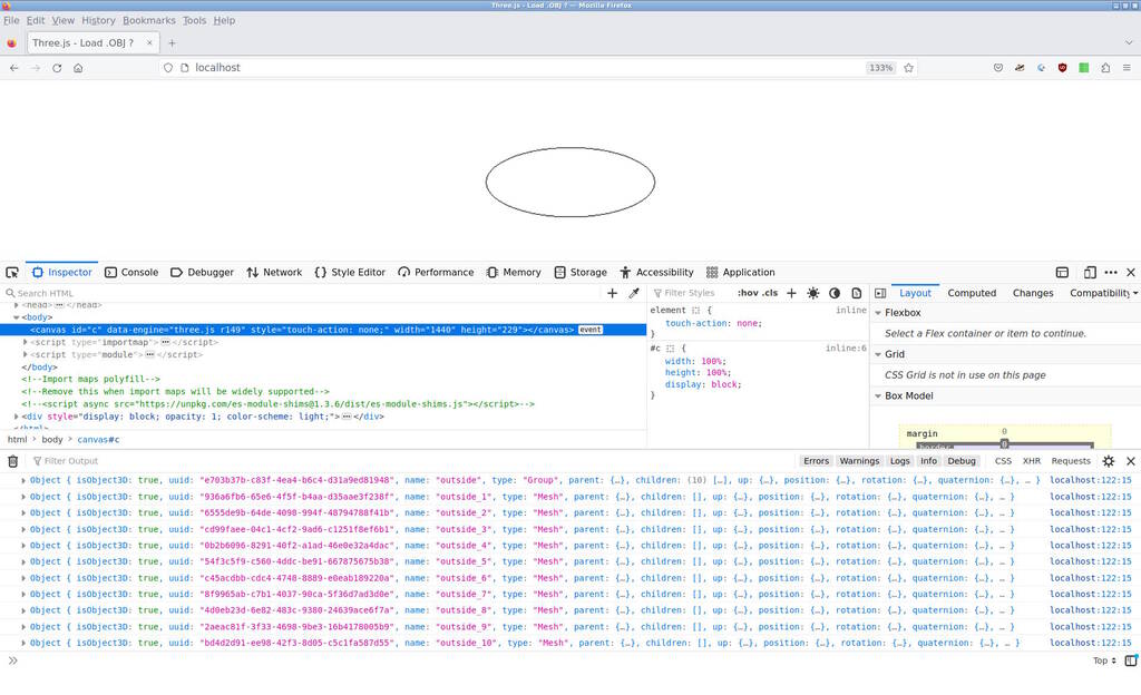
One of the listed objects that my console logged was 'outside_1'. I found the following code to be able to add the edge geometry to the scene:
var geometry = root.getObjectByName('outside_1').geometry;
var edges = new THREE.EdgesGeometry(geometry);

var material = new THREE.LineBasicMaterial({color: 0x000000, linewidth: 2});
var lines = new THREE.LineSegments(edges, material);
scene.add(lines);
The output of logobjects and the rendered line segments of 'outside_1' is:
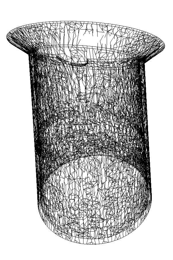
This looks promising, so let's go over all 'Mesh' types and add them to the scene. Here a recursive function that can accomplish that:
function addEdgeGeometry(object) {
  object.children.forEach((child) => {
  if (child.type === 'Mesh') {
    var edges = new THREE.EdgesGeometry(child.geometry);
    var material = new THREE.LineBasicMaterial({color: 0x000000, linewidth: 2});
    var lines = new THREE.LineSegments(edges, material);
    scene.add(lines);
  }
  addEdgeGeometry(child);
  });
}

addEdgeGeometry(root);
Unfortunately, this shows all of the mesh structure, which is far too many:
While researching Blender and trying to achieve a same way of rendering, I
became aware of an "angle" setting that makes a distinction between
which
edges should be taken into account. While browsing the
threejs API
, I found a similar setting
for the function
EdgesGeometry
. While threejs uses a default angle
of 1 degree which means that almost all edges of the mesh are incorporated,
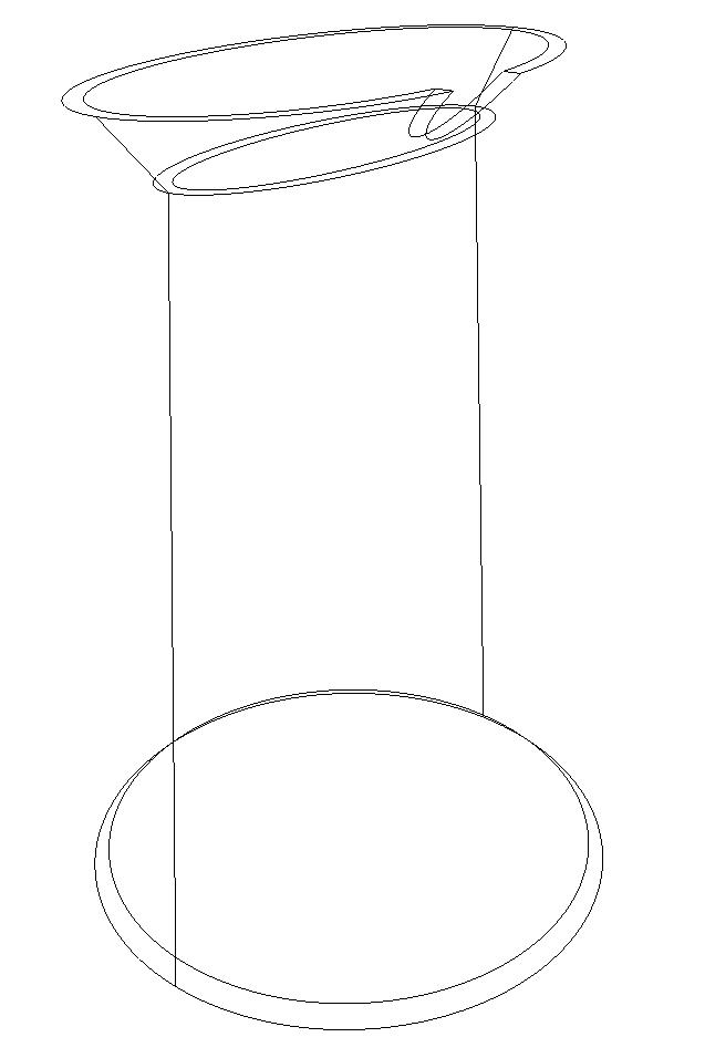
Blender uses a default value 134 degrees. Rendering with this degree gives
the following output:
However, this is not really what I want, because the lines are based on the mesh, the degree is arbitrary and I would have to find a correct setting for each particular model. What I want is an outline of edges, automatically computed. By turning the model, it is clear that it is not an outline that we have, but arbitrary lines from the mesh:
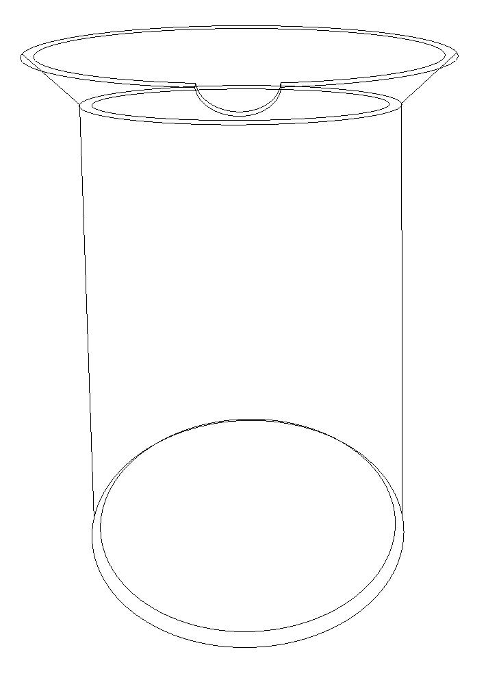
For now, I will simply render the object above without lines but I will try to accomplish my goal to render the outlines somehow in the future.
Update: Exporting the Images from FreeCAD
I was asked by a couple of people how I export 2D images from FreeCAD, so let me explain this and it involves Inkscape as well.
Exporting Vector Images from FreeCAD
In FreeCAD, I open the TechDraw Workbench and do TechDraw
➜
Insert Page
Using Template where I always choose
A4_Landscape_blank.svg
. This
will give you a new tab with an empty page. Then go back to the tab with
the model (it has a FreeCAD logo), select the object(s) that you want to
export, and turn the camera such that it matches what you want to export.
Then do TechDraw
➜
Insert View (you may need to select a page if you have
multiple TechDraw pages open) and go back to the tab with the page. The
object has appeared on the page and you may need to change the size in the
following way:
In the tree, go to the respective page which has a template object and a view object. Select the view object in the Model tab of the Combo View and in the Property/Value list, change "Scale Type" to "Automatic" or "Custom". In the latter case, you can adjust the scale in field "Scale". You may need to refresh.
Finally, choose TechDraw ➜ Export Page as SVG and you will get a true vector SVG of your model.
Postprocessing in Inkscape
I use two techniques to get rid of the borders that FreeCAD may add. I generally prefer the size of the SVG to be exactly the size of the drawing.
I open it in Inkscape and often do the following key sequence: Ctrl-A , Ctrl-G , Ctrl-Shift R , Ctrl-S , which is select all, group everything, adjust the page boundaries to the image boundary and save the image. Adjusting to the page boundaries can be found in File ➜ Document Properties ➜ Resize to content.
I also have a simple script for this that I call
is-fit-to-drawing
:
#!/bin/bash

# SPDX-FileCopyrightText: 2022 J.C. Mariscal-Melgar <jc@hsu-hh.de>
# SPDX-FileCopyrightText: 2022 Pieter Hijma <pieter@hiww.de>
#
# SPDX-License-Identifier: Apache-2.0

if [ $# = 1 ]
then
    if inkscape --version | grep "Inkscape 1.1.2" > /dev/null 2>&1
    then
	inkscape --batch-process --actions="select-all:all;FitCanvasToSelection;FileSave;FileClose;" "$1"
    elif inkscape --version | grep "Inkscape 1.2" > /dev/null 2>&1
    then
	inkscape --batch-process --actions="select-all:all;fit-canvas-to-selection;export-filename:$1;export-do" "$1"
    fi
else
    echo "USAGE: $(basename $0) <file.svg>"
fi
Tasks
Fab Academy
- Model a possible final project with 2D and 3D modeling software.
- Evaluate and select 2D and 3D software.
- Describe the processes in modeling in 2D and 3D sofwtare.
- Include the original design files.
Personal
- Model with raster images (used the raster images to include it in the CAD file to adapt the paramers to fit).
- Model with vector images.
- Render the model (rendered it within the website).
- Animate the model (the model can be manipulated in the website).
- Simulate the model.