Sketch
Introduction
I have many, many ideas for a Final Project, but last Wednesday we discussed it with Henk and my fellow students and then it became clear what the most promising one was. Let's first list my ideas: Chip lithography (undoable), a device along your spine that gives you discomfort when having a bad posture, a small robot mouse for my cat that does collision avoidance but is nonetheless fast, and I most likely have already forgotten a couple of other ones.
The project that is most promising is most likely a device to warm up your eye lids. This has to do with a condition that I have. In some periods of the year, especially when I have a cold, I get sticky eyelids (they stick together after a night's sleep for example) and my eyes are prone to tearing.
Current Situation and Motivation
The advice from the ophthalmologist is to use warm compresses which can improve the situation. After having tried that to no avail, I read a paper that explained to me why warm compresses should work and more specifically under which conditions it should work.
An eyelid has so-called meibomiam glands that produce an oily substance which prevents your eye tear film to evaporate. I have meibomiam gland dysfunction which means that the oily substance has a more solid form. This results in my eye tear film being not oily enough causing evaporation that my eyes compensate with tearing.
The cause of meibomiam gland dysfunction is that the melting point of the oily substance is higher than normal, causing it to be more solid. Applying heat makes it flow again. The reasons for why the melting point is higher for some people are not well known but age is a factor.
Unfortunately, I can't trace back the paper that I read years ago, but the conditions for improvement were very clear. Firstly, the applied heat should be very high, so high that you can barely take it. Secondly, they tested the method on subjects, and twice a day 5 minutes improves the situation. Twice a day 10 minutes is better, twice a day 15 minutes is even better, and twice a day 20 minutes has no measurable effect. So, the conclusion is that applying heat twice a day for 15 minutes is ideal.
The advice that I received, applying a warm compress is in principle a good suggestion, but the details matter much: What is warm and how long does a warm compress stay warm?
I resolved my issue by adopting a technique, sketched below. I apply this technique twice a day for 15 minutes over the course of two weeks and most of the time, my tearing eyes have resolved itself. I typically need to do this after I've had a cold.
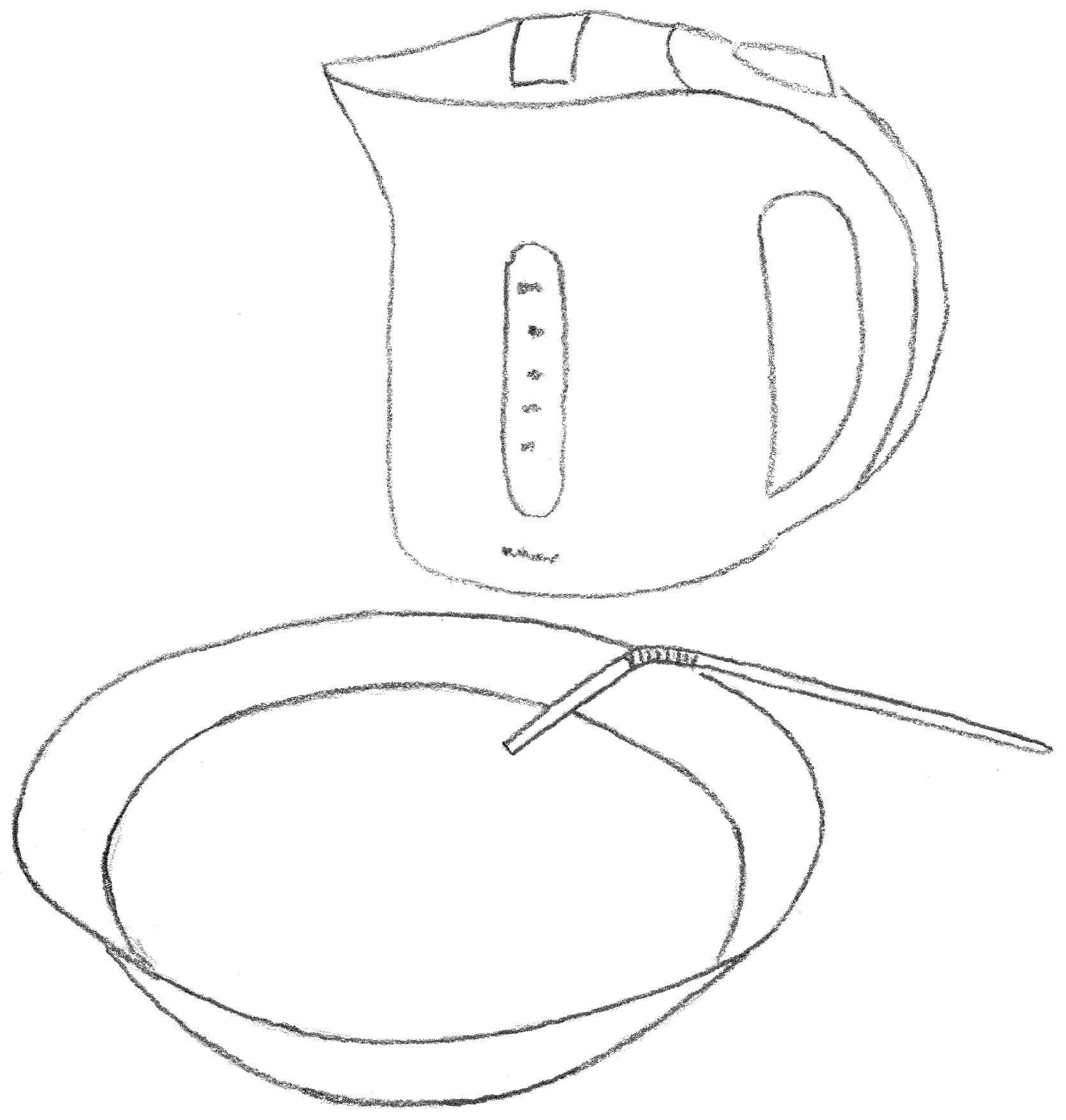
So, the technique works, but it annoying, boring and borderline dangerous: In a water boiler, I bring water to a boil. In the meantime I prepare a bowl with water so hot that I can barely resist it. I set a timer to 15 minutes and start a podcast on my computer. I submerge my face in the water in the bowl and use a straw to breathe. I use my fingers to stir the water gently because if I don't, I get used to the temperature very soon. Apparently, the water around my eye lids cools; in any case, stirring makes it feel warmer for longer. Every once in a while, I pour some new of the boiled water to bring the temperature up to level. This is a very imprecise action and sometimes, I have to pour some new or wait a bit until the water reached a level that I can bare. Needless to say, there is lots of room to improve on this.
Project Idea
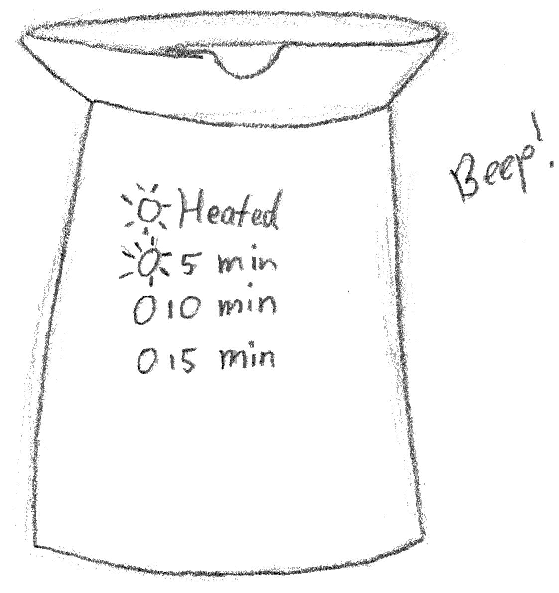
My project idea is something that looks like a water boiler but on top there is a cut-out in which my face fits. It has indicators for reaching the right temperature and notifies the user with a beep when the water has reached the right temperature or when 5, 10, and 15 minutes have passed:
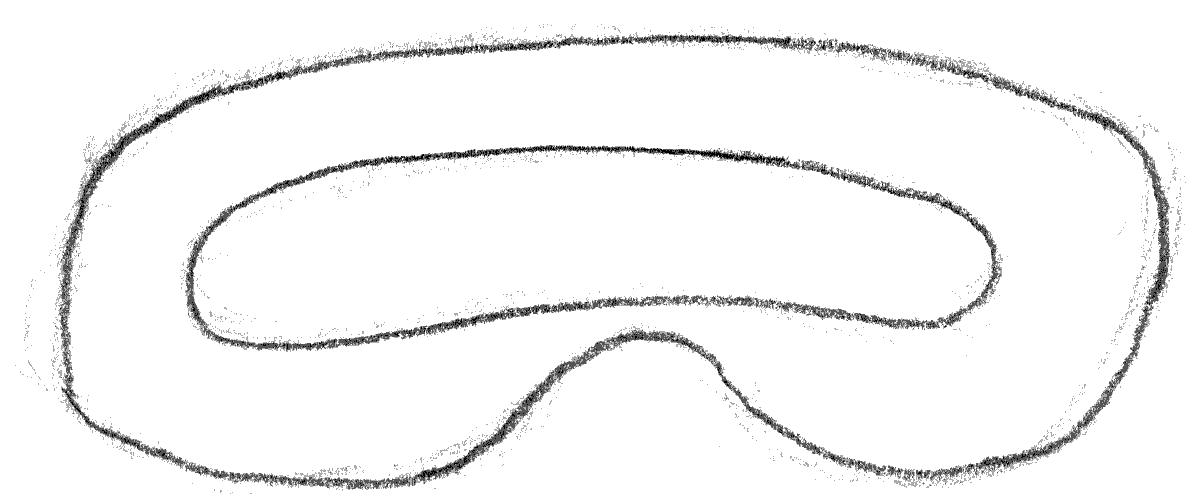
The top view shows an impression of a cut-out that should perfectly fit my face but leaves my nose free to breathe:
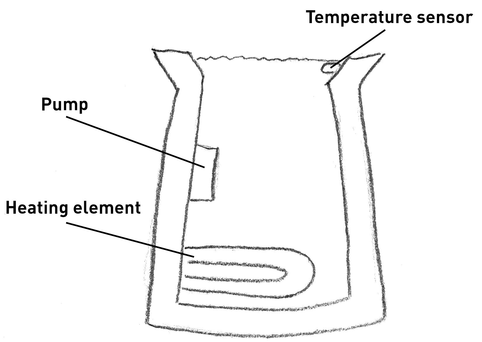
There is a temperature sensor that drives a heating element and there is a small pump that arranges for a constant flow of water as can be seen in this cross section:
On turning on the device, it heats the water and makes it known that the water has reached the right temperature. The device has two buttons to increase or decrease the temperature:
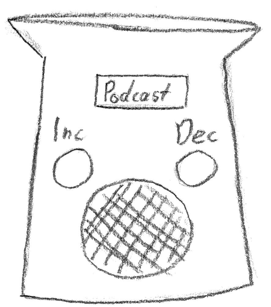
Additionally, it is able to play my favorite podcasts or it may produce relaxing or meditative music in order to make what is now a chore into a nice relaxing moment of the day.
Relation to the Fab Academy Program
I believe that this project is able to use many of the techniques in the Fab Academy program, making it also applicable to spiral development. Potential applicable techniques are:
- CAD, for the design of the various components
- Cutting, for the housing
- Embedded Programming, for the podcasts, and controlling the temperature and flow
- 3D Scanning and Printing, scanning my face perhaps, printing parts for the housing?
- Machining, for the housing perhaps?
- Electronics Production, for the boards
- Molding and Casting, for making something that fits my face well
- Output Devices, heating element on a different circuit with higher voltage
- Input Devices, measuring the flow of water, temperature, user input
- Networking and Communication, several boards that interact, the podcast client
- Interface and Application Programming, the podcast client
Potential Issues
The most likely issue has probably to do with interacting with water because electronics and water don't match very well. It will be necessary to seal off all the electronics from the water. However, there need to sensors and actuators in the water as well, so this may be quite a challenge.
Another issue is the heating element that needs much more power than 5V can deliver , so there needs to be another circuit that is switched on somehow by the electronics that regulate the temperature.
Writing a podcast client may also turn out to be quite challenging. There needs to be a speaker and a headphones connection would be nice as well.
Project Management
I believe this project suits itself very well to spiral development. We could start from my current situation and try to improve on that step by step. For example, making a bowl where I can turn on a heating element with a switch now and then would already be an improvement. In a next iteration, we could add a pump, and afterwards, we could add a temperature sensor for the water. We could then add a dedicated housing and finally a piece that fits my face perfectly so I don't need straws to breathe.
Modeling the Final Project
I would like to get close to what I have drawn and as said above, I will first focus on the outer body. It is a conscious choice not to think about whether machining/printing such a design is possible, simply because I have not enough experience with fabrication techniques. So, for now, I simply model what I drew and I will adjust later if it turns out that it is impossible to make.
Design Rationale
The drawn outer shell is round at the base, but elliptical at the top. Somehow they should "connect", so I believe I require a loft for that, although I'm not sure.
The outer shell is round at the bottom to give the device stability when my head rests on it. Since my eyes form the only part that should be heated, the top part is elliptical. Inbetween the part where my face rests and the bottom, there is something that I will call a neck that tapers out for a comfortable fit for my head.
So, some terminology: we have the round base , there is the neck that supports the elliptical face part , the part where my head will rest.
Approach
I will approach the design by using master sketches in 2D. In this case, a series of top-down master sketches and a front master sketch will provide enough information to understand the design in 3D.
In addition to the master sketches, the design will be fully parametric since I do not know what good sizes are and how large several components will be.
Parameters
I first started defining the parameters of the base, face part, and neck.
I created a separate
params.FCstd
with a spreadsheet called
"params". This allows me to quickly choose parameters in expressions
and a
separate file allows to reuse various parameters for different components.
| Parameter | Value |
|---|---|
| width_base | 100 mm |
| width_face_part | 100 mm |
| depth_face_part | 50 mm |
| height | 200 mm |
| height_neck | 180 mm |
| width_neck | 80 mm |
| depth_neck | 50 mm |
Master Sketches
The master sketches are drawn in the Part Design workbench and the three top master sketches (with a top view) only consists of circles and ellipses:

All geometry is fully constrained with the middle point on the origin using the dimensions listed above. The ellipses are constrained to be fixated to the X-axis to prevent rotation.
The front view master sketch shows the outline on one side. This sketch was created by allowing the external geometry of the circle and two ellipses to be used as anchor points, allowing me to draw the two straight lines connecting the top ellipses. The front view also shows that the two ellipses have been placed at the correct height. This is done by means editing the Z value of the Position of the Attachment property of the Sketch.

The following image provides a bird's eye view to better understand the front and top master sketches.

The outside body can now hopefully be created by applying a "loft".
Applying Loft
This required much experimentation and my limited knowledge was the culprit. I would assume that I needed to loft over both the base and the two ellipses, but this resulted in the following:

It looks nice, but it won't have room for the logic. I assumed that the neck would have a separation from the base and the face part. What was required was to apply two lofts: the neck to the base, and the neck to the face-part ellipse:

Notice that the two lines of the front view master sketch are also drawn, to show that this design follows the outline I had in mind. The parameters of this version have been slightly changed compared to the images above.
Cutting out the inside
The above images only a solid, but there should be a basin and heating elements inside, so let's use the "Cut" boolean operation to cut out an inside. Since I am not modeling the other components as of yet, I decided that I simply make a cutout such that the outer shell has the same thickness everywhere.
Unfortunately, my FreeCAD version doesn't have an offset tool in Sketcher,
so effectively, I drew the same geometry again with formulas such as
width_base - 2 * thickness_body
. I then apply the boolean operation
"Cut" to achieve the following:

Cutting out the Nose
Cutting out the nose boiled down to drawing a half circle. This was done
on the XZ plane and then with the Attachment feature of the sketch, I
wanted to place at the height of parameter
height
. I expected to
need to change the Z value of Position, but instead I needed to change the
Y value. It puzzles me why changing the Z value brings the sketch forward,
along the Y axis, whereas changing the Y value brings the sketch up along
the Z axis.
After placing the nose sketch at the right position, I could simply extrude it and use a boolean operation to cut this out of the main body. The resulting geometry is:

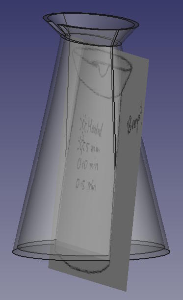
Mimicking the drawn dimensions
To find an approximation of the dimensions that I drew by hand last week, I loaded the image in the Image workbench on the XZ plane and scaled the image such that it approximated the dimensions that I had modeled. Since the drawn image uses a different perspective than a full front-view, I tilted the image pane such that when looking at the 3D model from slightly above, it matched the drawing. The following screenshot from FreeCAD shows the tilt of the image to match the perspective from the front. Making the 3D model transparent allows me to adjust the dimensions of FreeCAD.
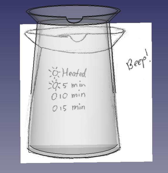
The front view looks like this. You can see that I tried to tilt the image pane to the direction of the camera where the camera is positioned such that it mimicks the perspective on the hand-drawn image:
Dimensioning the design to match the hand-drawn sketch, the model looks like this:
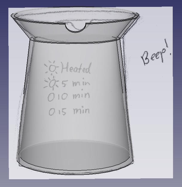
The resulting model:

The parameters to achieve this are:
| Parameter | Value |
|---|---|
| width_base | 170 mm |
| width_face_part | 185 mm |
| depth_face_part | 90 mm |
| height | 215 mm |
| height_neck | 180 mm |
| width_neck | 130 mm |
| depth_neck | 50 mm |
| thickness_body | 5 mm |
| width_nose | 30 mm |
I received the comments that these parameters seem many. However, I want to stress that all parameters are used to mimick the hand-drawn dimensions. I think that in mechanical design it is logical to use as few parameters as possible, but in this case, the design is based on a hand-drawn sketch. In that case, it is good to have the flexibility to be able to adjust.
Reflections
I lost much time with not properly understanding loft. In hindsight it is very logical that the operation I had in mind would not work, but I guess I had a bit of tunnel vision there.
While changing the dimension, I found a bug in the parameters: The width of the ellipse of the face part had been set to the width of the base, so the design was broken. It was very clear that a parameter was wrong and after locating the right expression, it was obvious that the expression was wrong.