Smart Suspension Load Backpack
Problem statement –
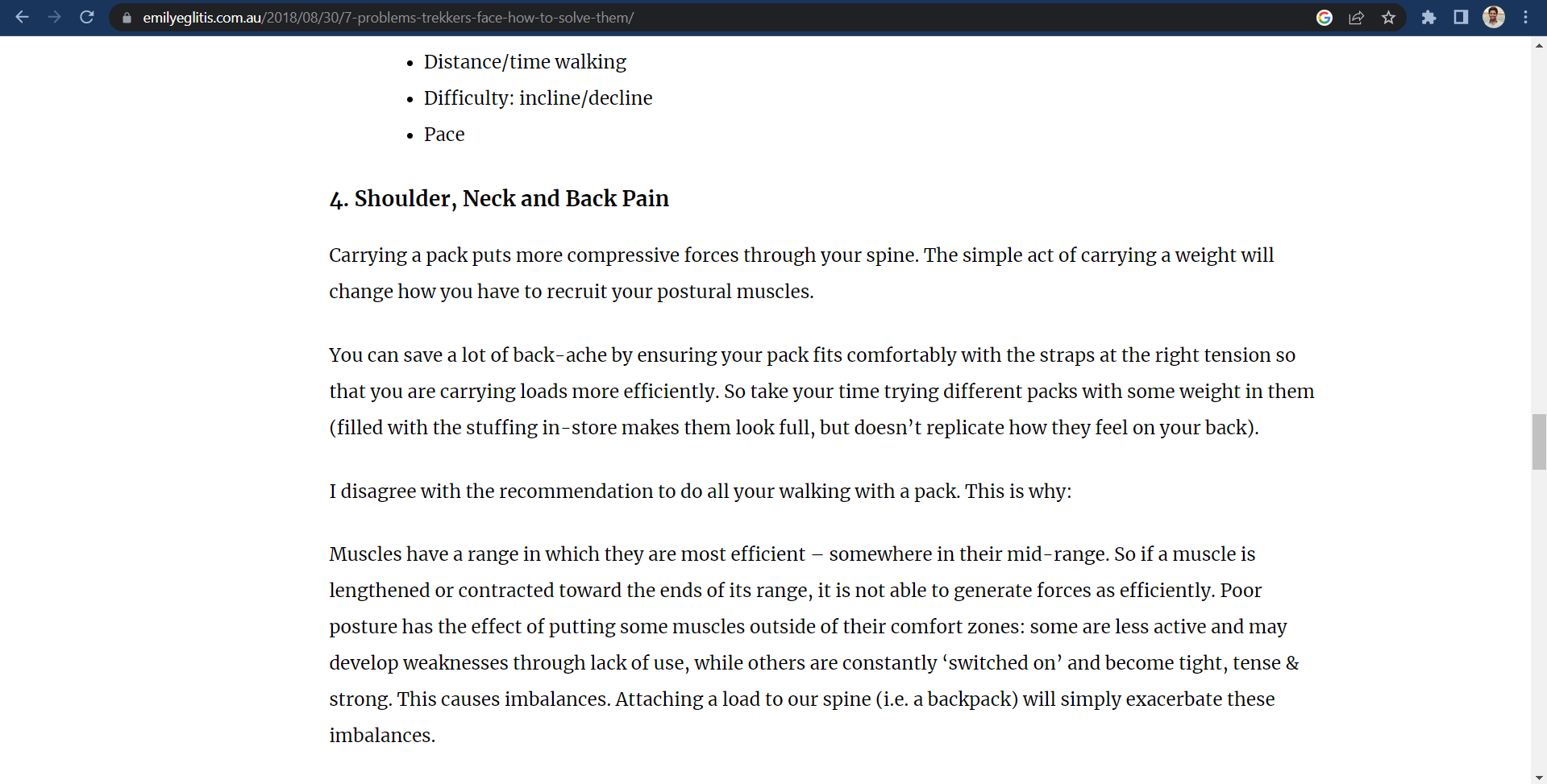
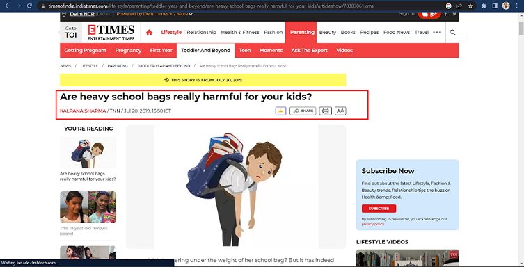
Backpacks are the preferred choice for travelers due to their convenience and ease of carrying. Even trekking enthusiasts, known as trekkers, rely on large backpacks to accommodate their needs during expeditions. Additionally, armed forces utilize these bags to transport heavy loads efficiently.
However, the act of walking or running while carrying such substantial weight imposes a considerable dynamic load on the human body. This excessive load can potentially inflict severe damage on various body parts, including the back, shoulders, legs, knees, and other vulnerable areas.
School bags typically weigh around 4 kg when comparing different types of backpacks, while trekking or big traveling backpacks can reach up to 11 kg. In contrast, members of the armed forces often carry an immense load of approximately 30-35 kg. One can only imagine the tremendous impact and strain this dynamic force places on the users' bodies. It is imperative to acknowledge the potential risks associated with carrying heavy loads and take appropriate precautions to minimize the adverse effects on the human physique.

Solution
By Addting a Suspension machansim into backpacks can floate bag in virtical direction, i am using springs as a suspension mechanism
Bungee cord is also a option for this, but due unavailibility of customized bungeecord in india, i go with springs.
Electrnics will be added to the system for providing extra functionality & Monitoring system.
Objective
Objective behind selection of this project is develope a prototype of bag that can improve user experience of a trakkers and travellers of travelling in least amount of cost.
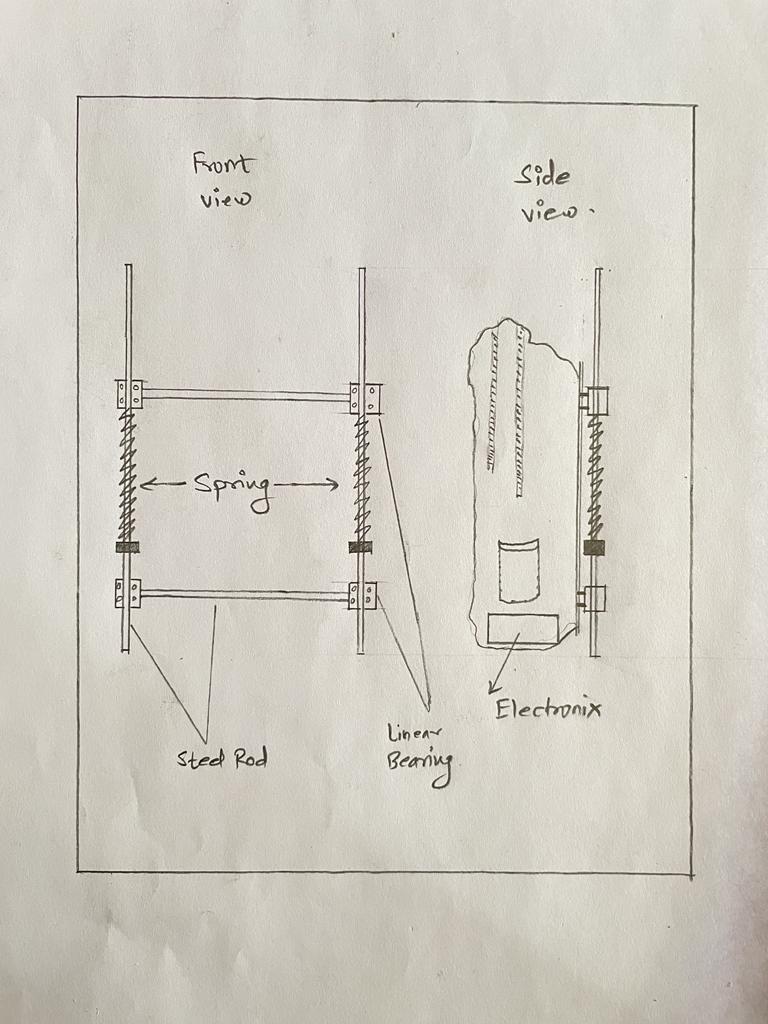
Final Project Sketch
Sketch
Presentation
Components used
Mechanical Components
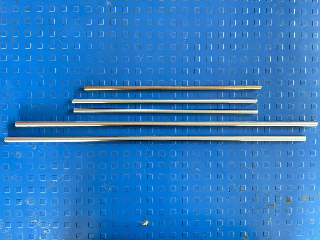
Used 10 mm Diameter steel rod as to support entire suspension mechanism. Used 2 rods of 500 mm length.
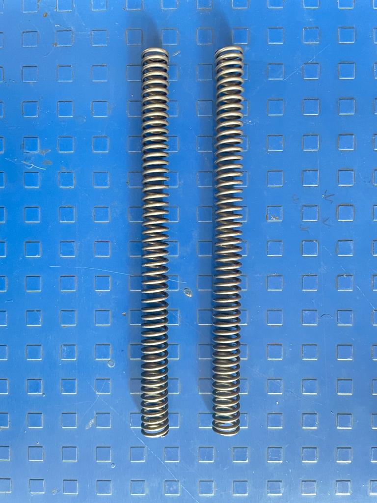
Used 2 springs to provide suspension to the weight. Springs are customize and designed to sustain upto 10 kg of load.
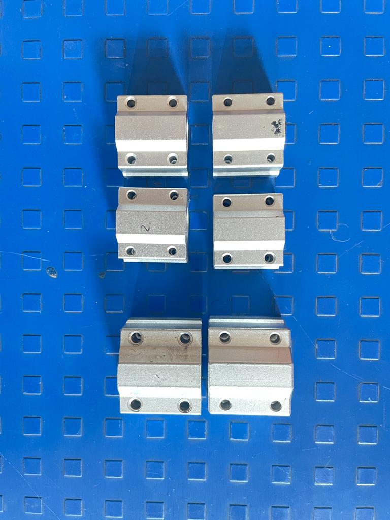
To provide support to suspension mechanism I used 4 linear bearing with inner diameter of 10 mm.
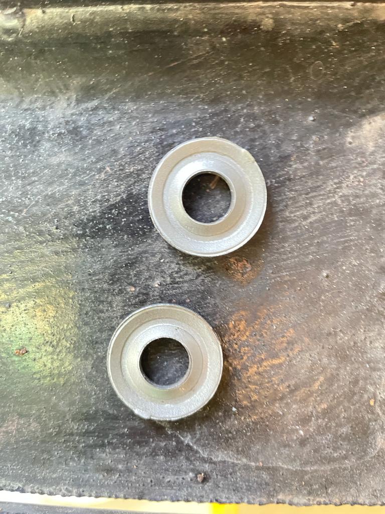
Used these types of washer to support and fix one end of spring.
Electronics component
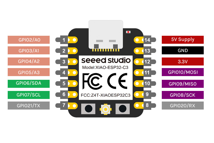
Used XIao ESP32 c3 module.
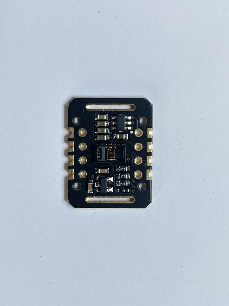
used MAX30102 blood oxygen measureing sensor in the system.
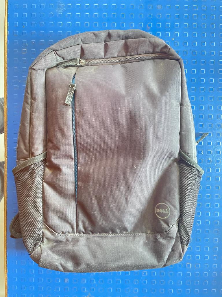
Fabric Material
Used old unused bag for the project by doing modifications into it.
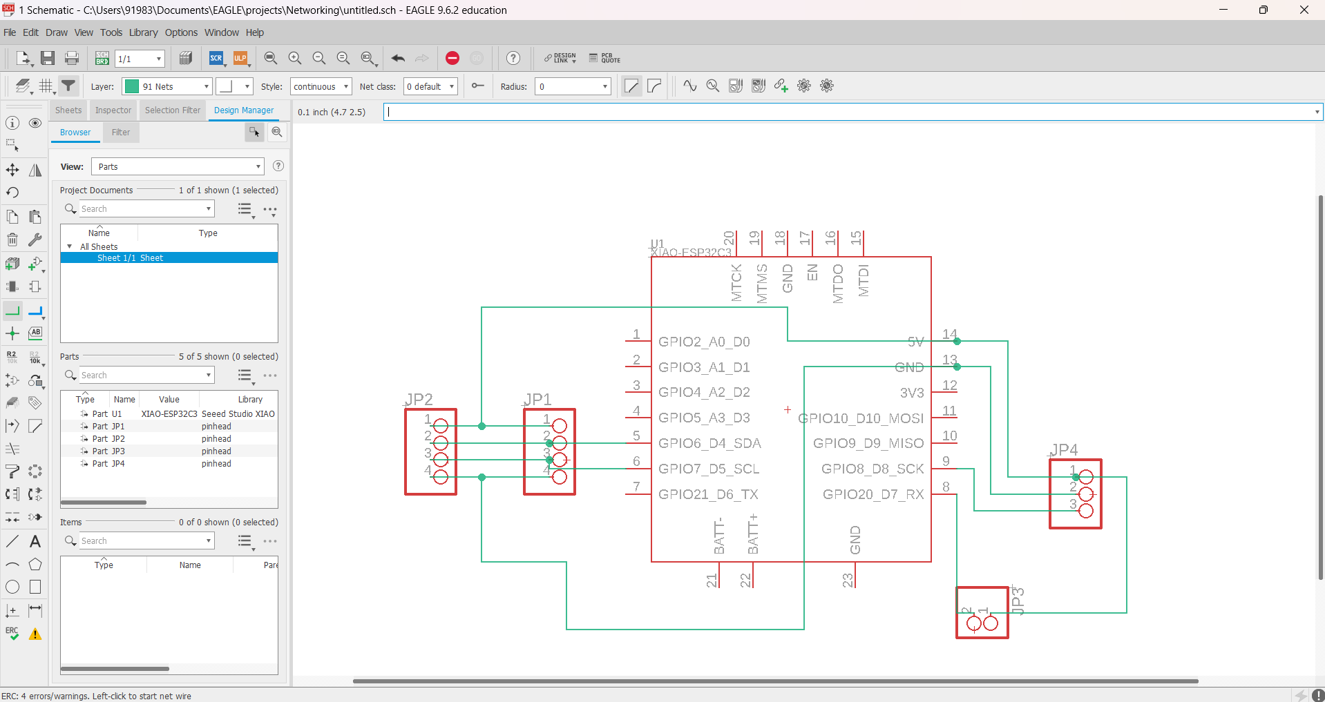
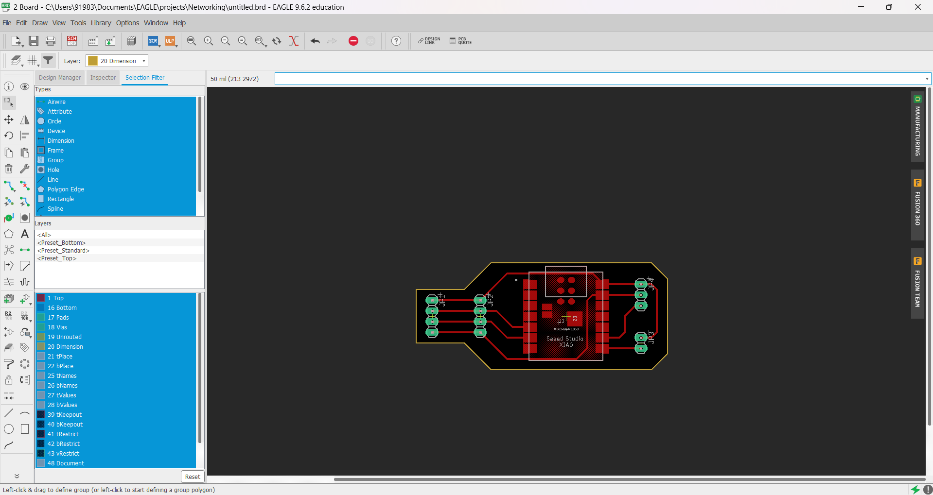
Electronics Design
As I am using AHT sensor, Max30102 and oled display and those all devices works on i2c protocol so I have designed a board according to that.
Board Schematic
Board Design


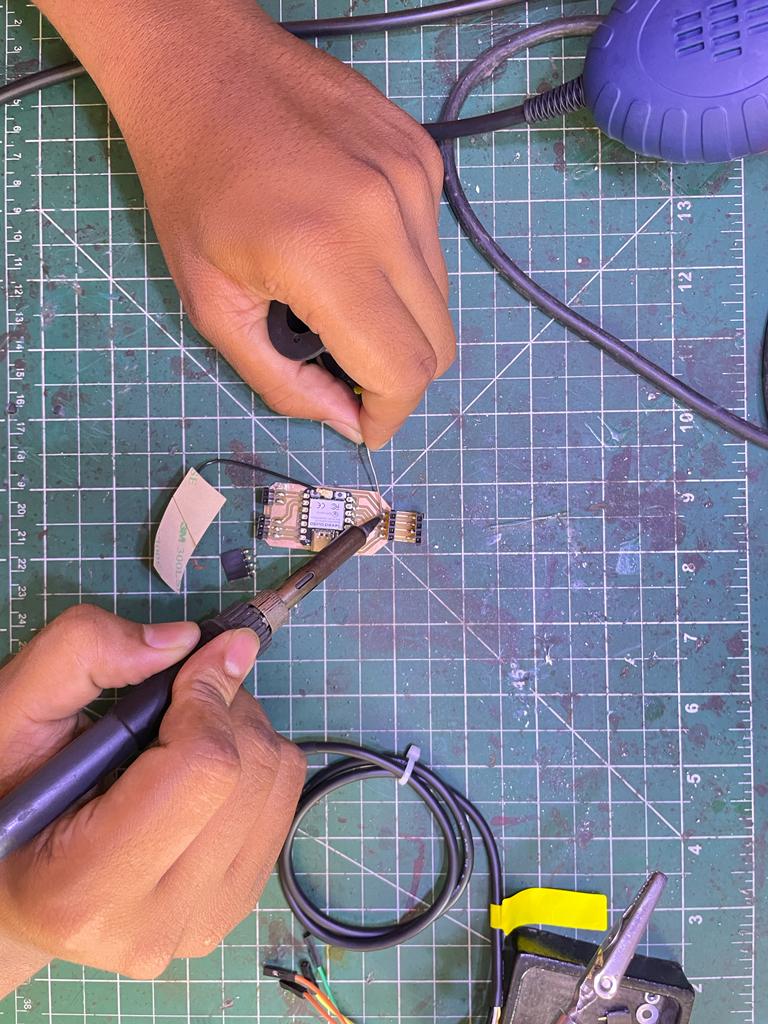
Soldering
Soldered a SMD microcontroller along with 4 pinheads.
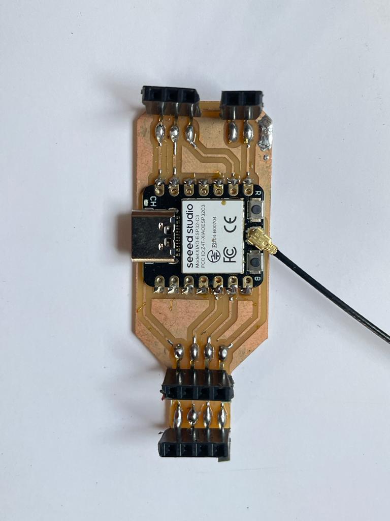
Final Board
After doing soldering the final board is looking like this.
Electronics Testing
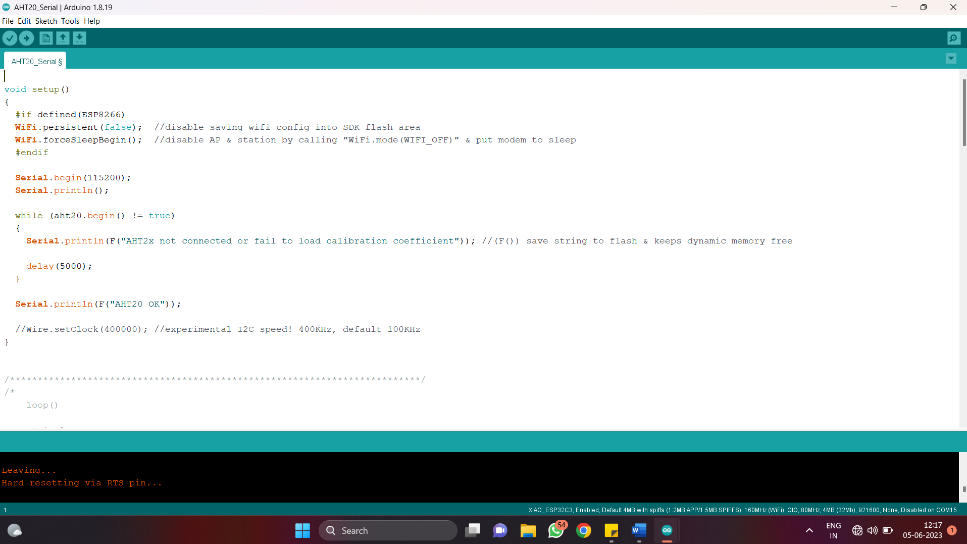
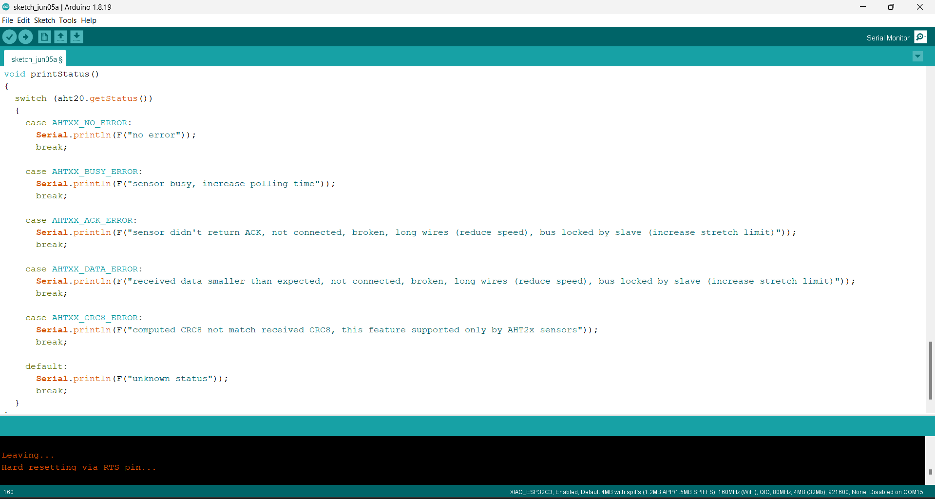
Testing of AHT sensor
Downloaded library for AHTv sensor for Arduino Ide.
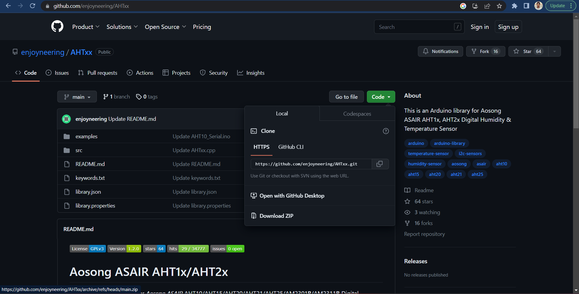
Then I run the example code for the testing sensor.
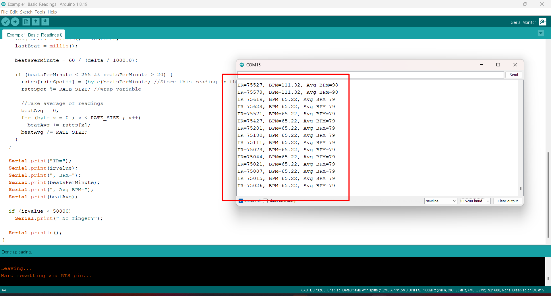
Testing of MAX30102
I have also downloaded library for MAX3010x for Arduino Ide.
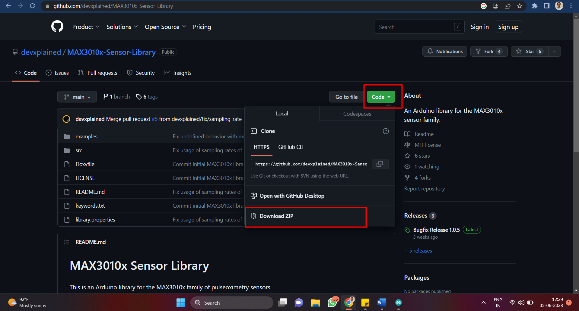
But I faced an issue with the library that I downloaded form GitHub. So by doing some research I fount out that Arduino ide has the require library. Then I used that to run the code.
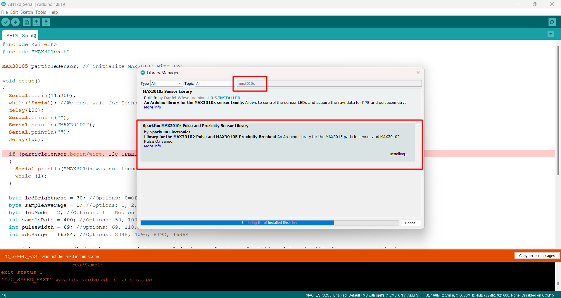
Used example code to test the Max30102 sensor.
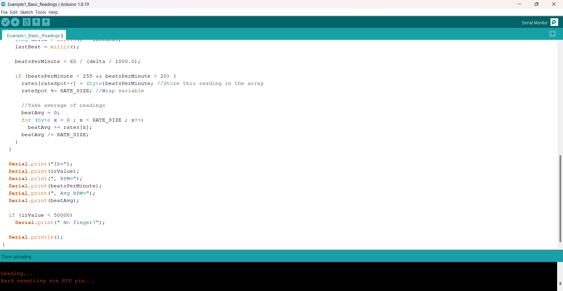
Successfully able to get values of the heartrate.
Combine Testing
Initially I faced lots of issues when I tried to combine codes for both the sensor, then I took helped form chat gpt to avoid mistakes
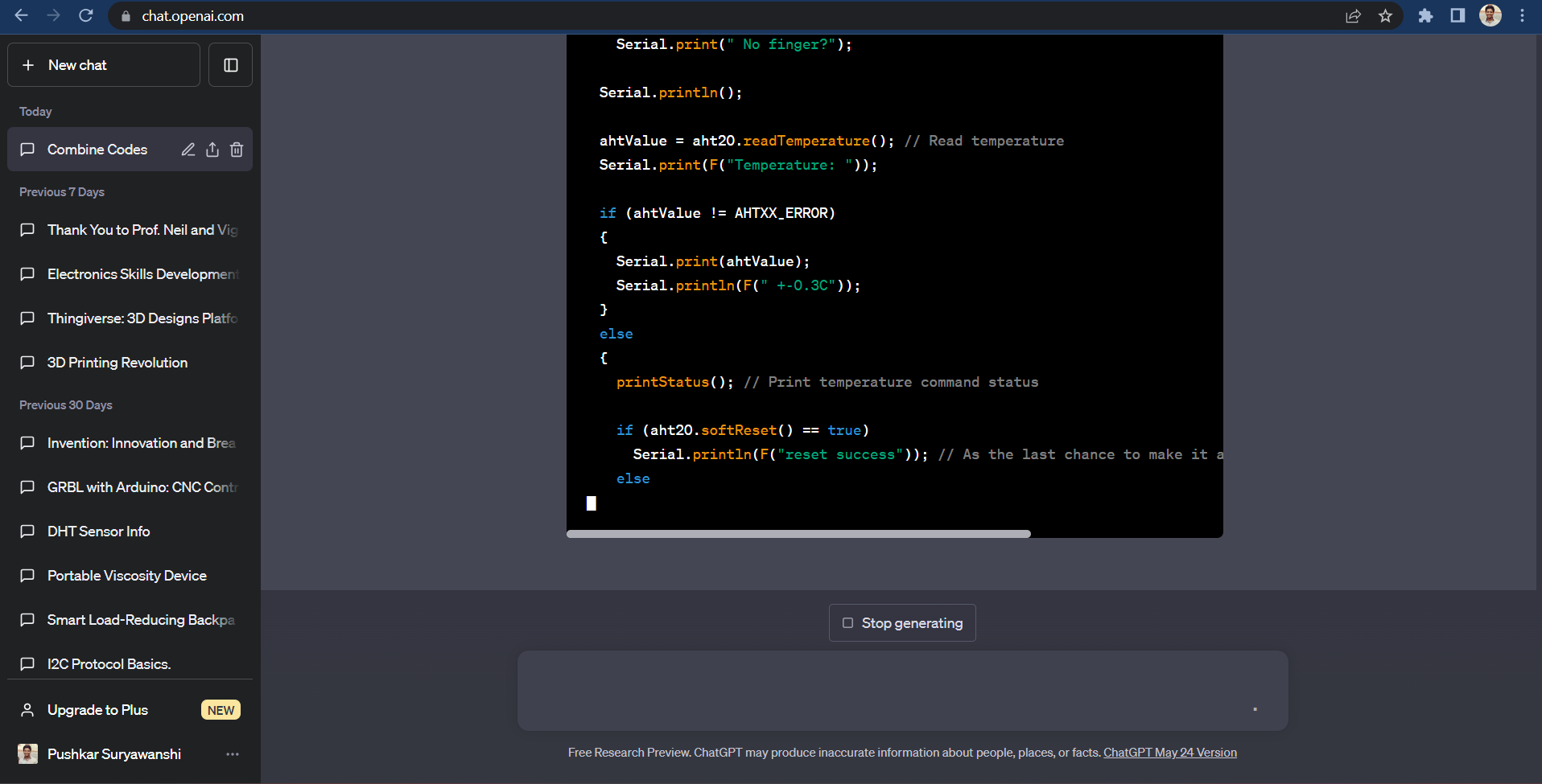
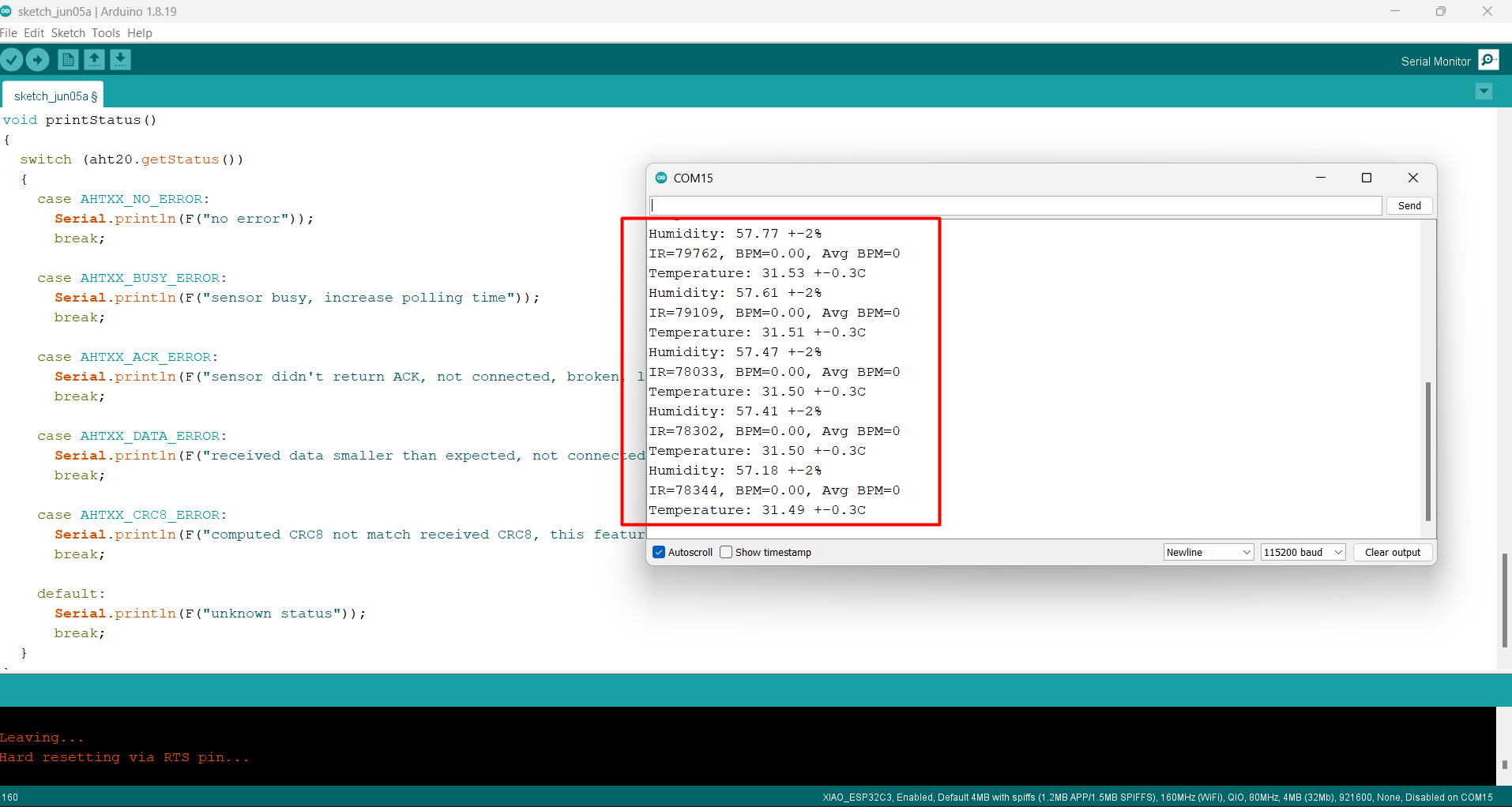
Final program to get the values of both the sensor simultaneously.
Able to see the values calculated by the sensor.
Digital Fabrication
3D Printing
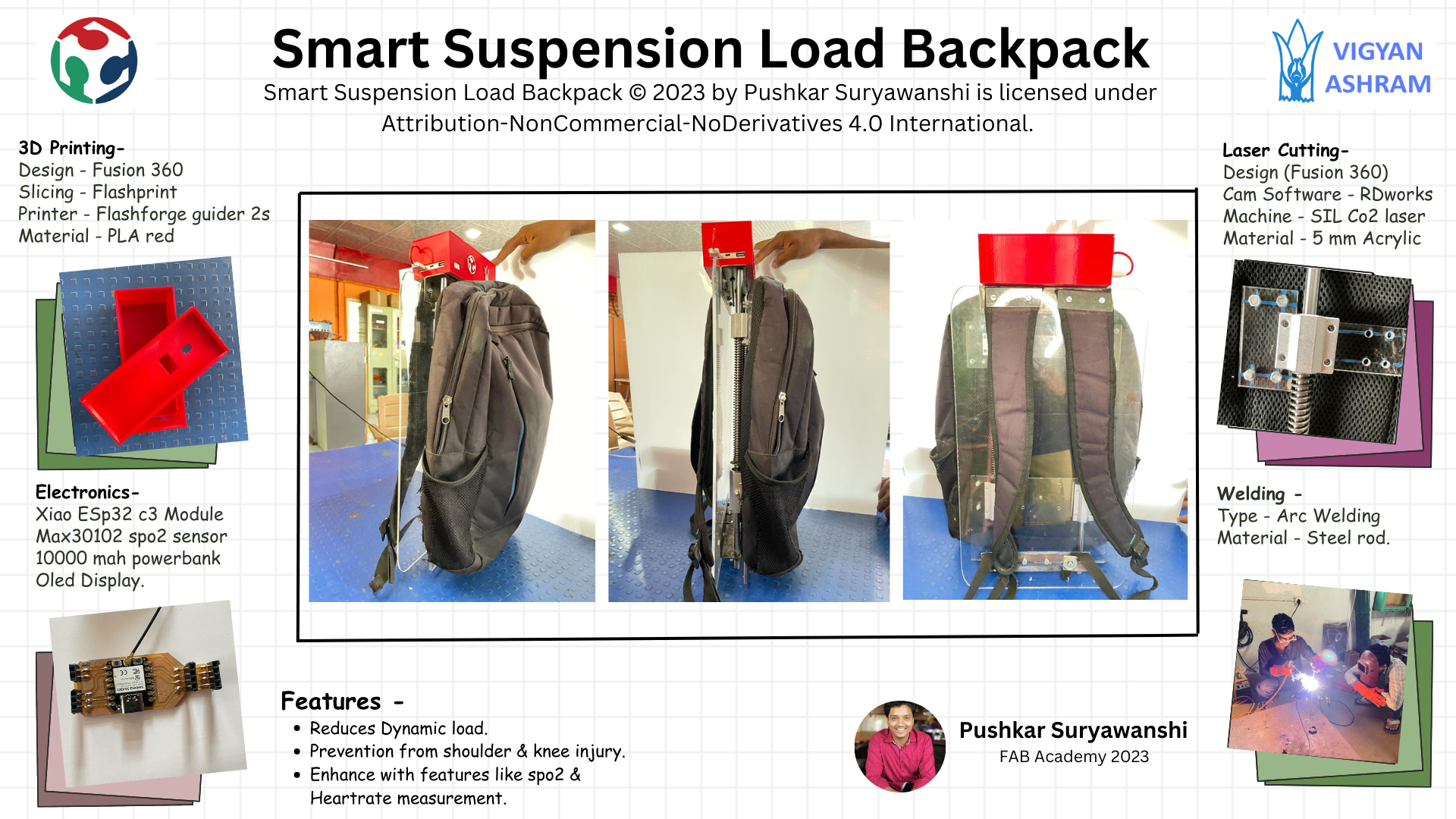
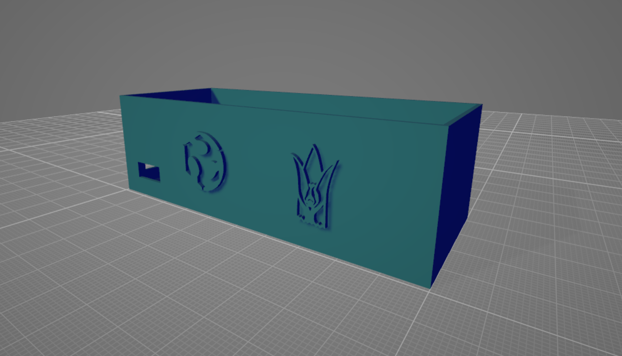
I used 3D Printing for making electronics assembly box.
I have designed a model using fusion 360
Used Flashforge guider 2s model with Red PLA material.
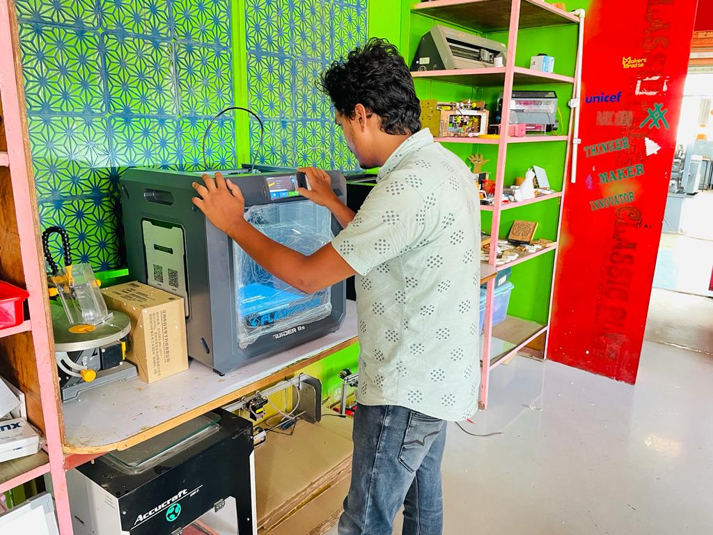
Got very smooth finishing and tight tolerance.
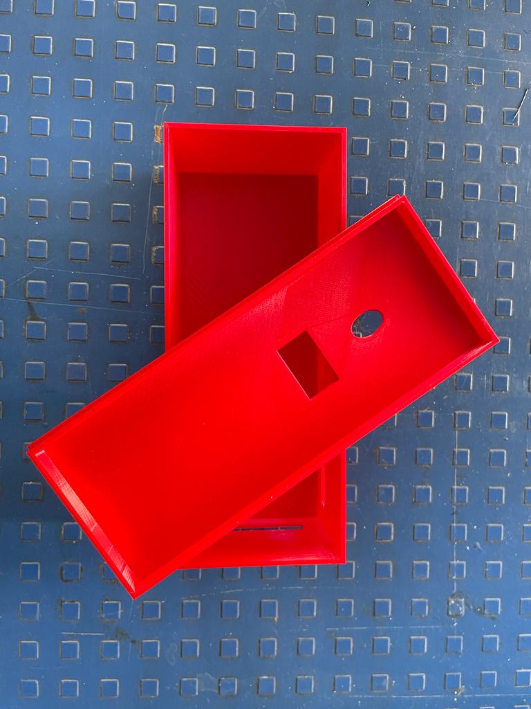
Fix my electrnics into that and did testing on it.
I also modified my electronics and added a buzzer into it.
and i programmed the micro-controller in a way that if sesnsor records heartbeat is extented over count of 70 then it will be on.
Buzzer sound is indication to the user about his high heartrate.
I Did print another small finger casing to fix sesnor to my finger for contineous monitoring.
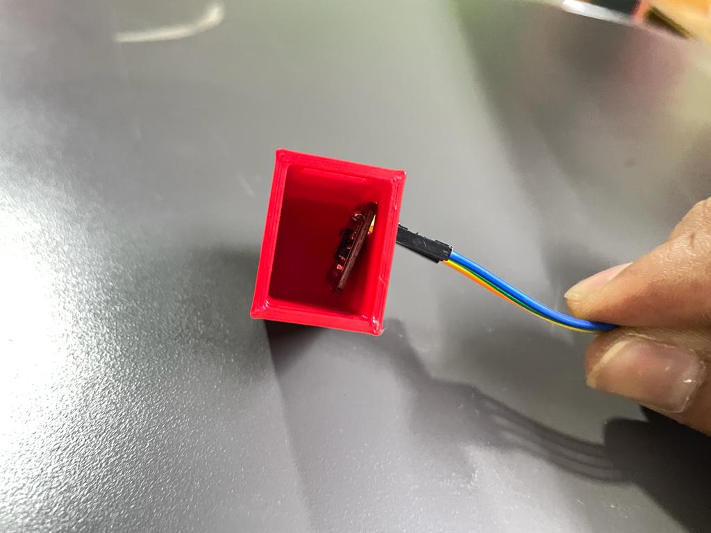
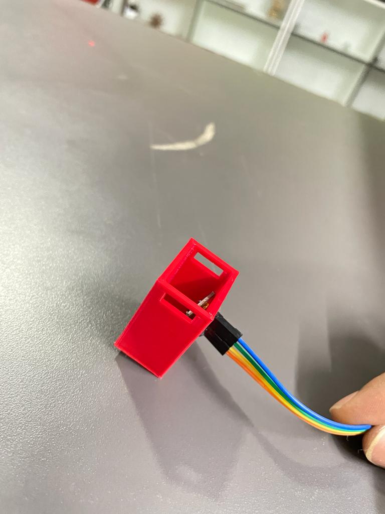
After all the the system will work like this.
Laser Cutting
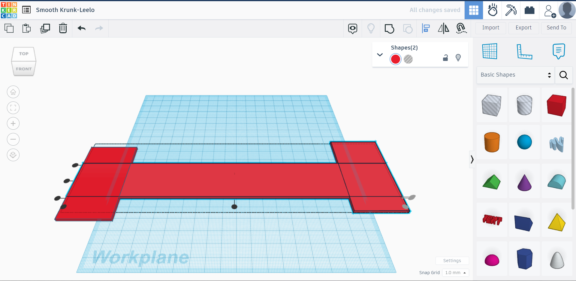
By taking require measurements, I design a plate used for the bag mount using tinkercad and downloaded a .svg file initially
As we use Rdworks software for laser cutting applications to generate tool paths, we must require a .dxf file of the design. Then using the online converter downloaded .dxf file.
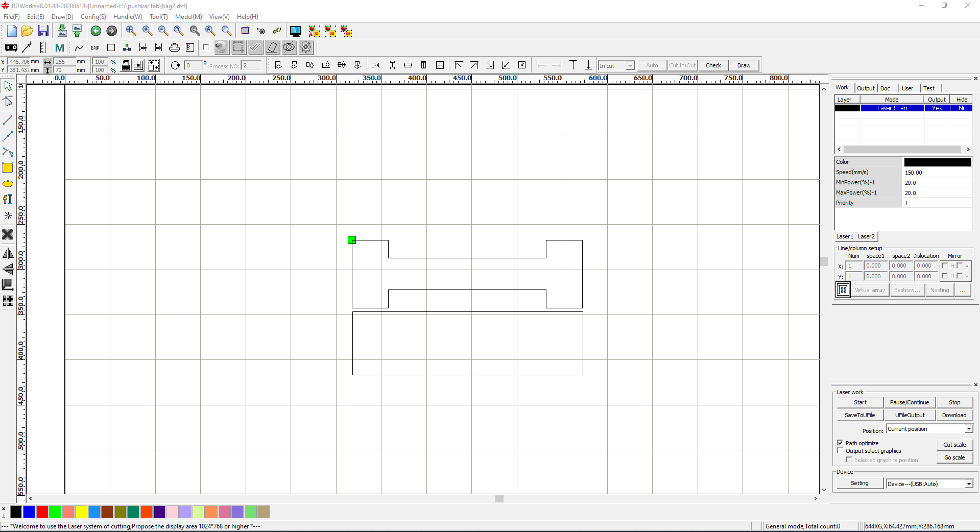
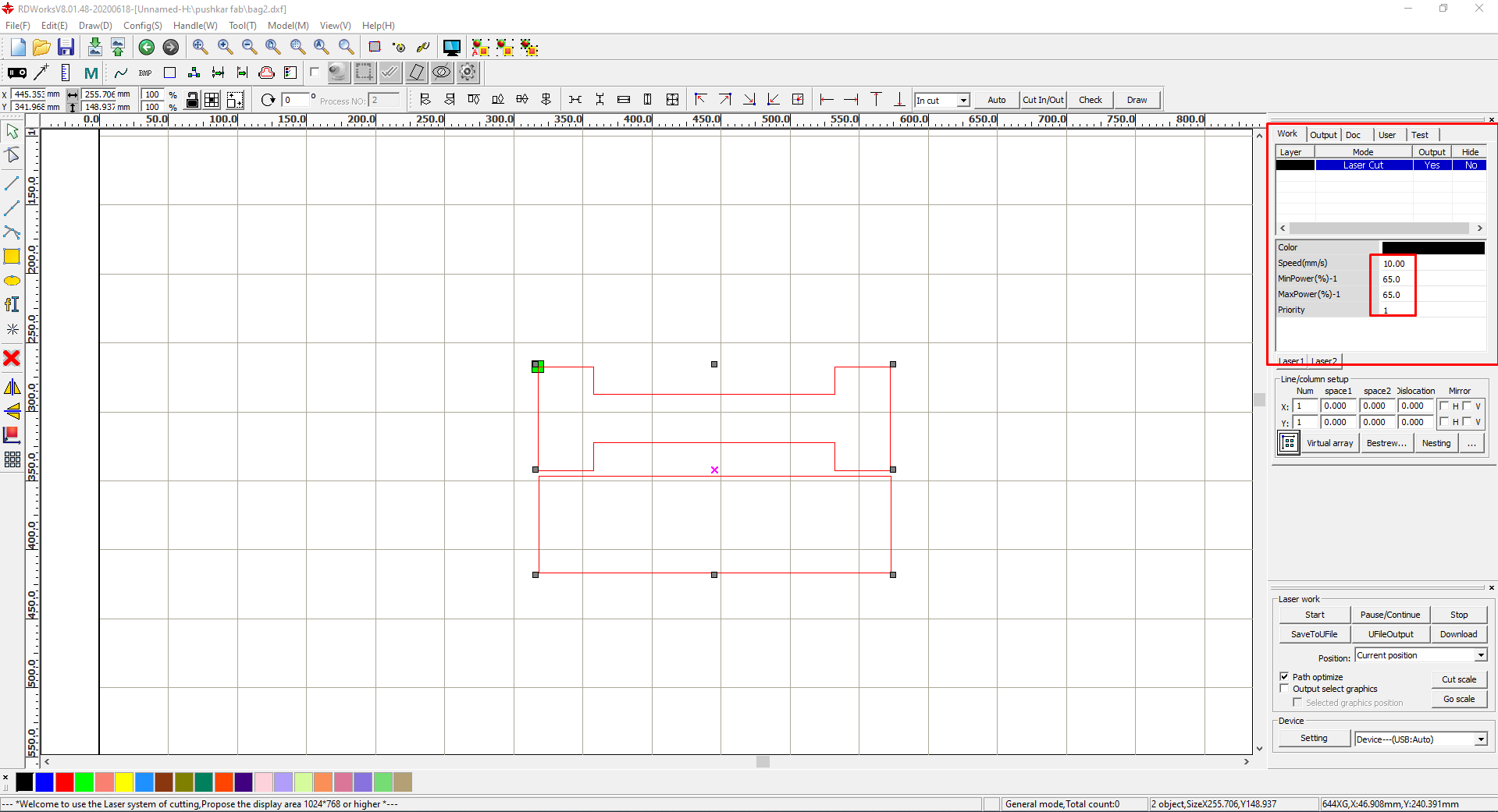
Generated tool path for cutting process by taking power value= 65 and speed = 10mm/s.
Set up machine levelling and used 5 mm thick acrylic sheet.
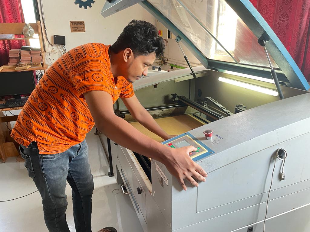
Final laser cut Parts.

This is how I used those laser cutting parts.
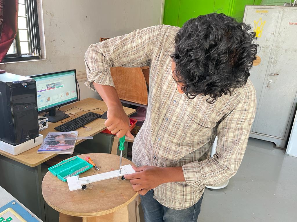
Assembly of mechanism
After getting all the necessary parts and assemblies, I started to assemble the design.
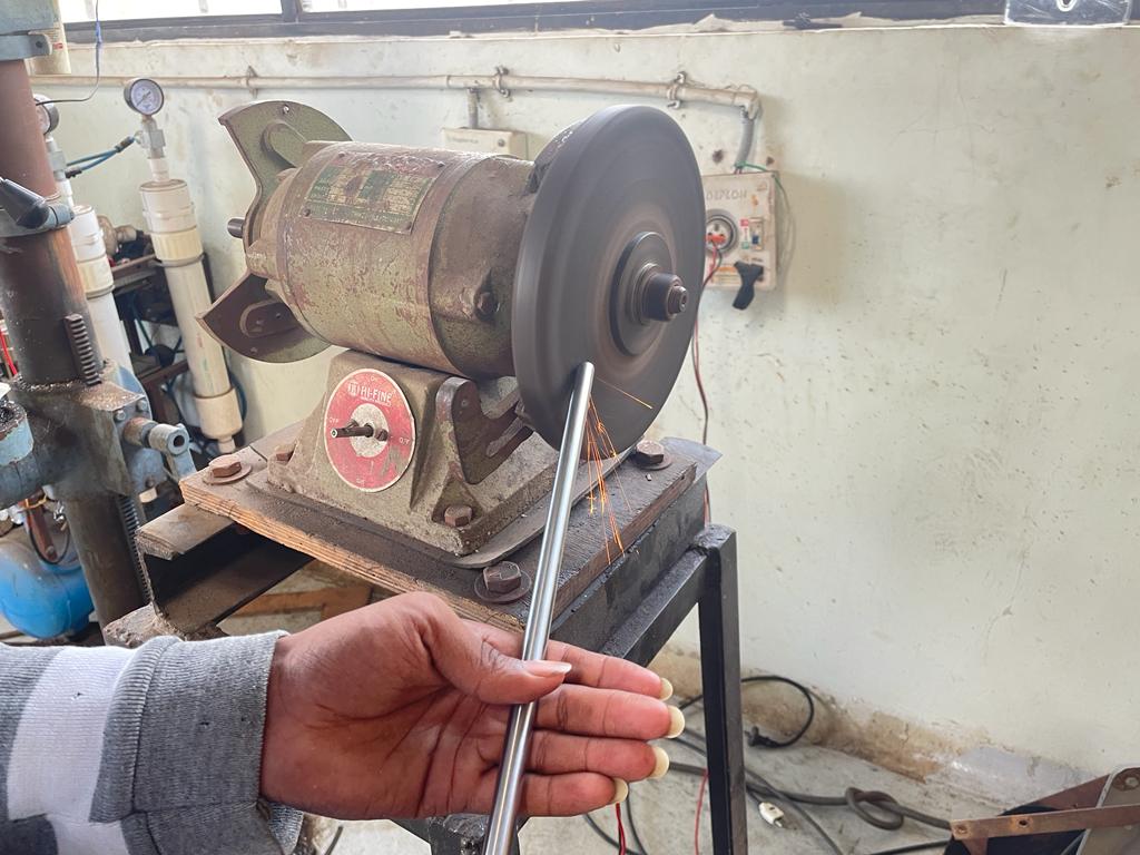
I used two 500 mm length steel rod with 10 mm outer diameter.
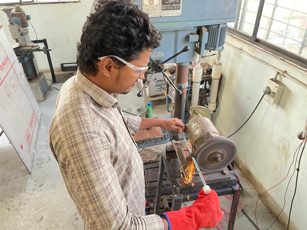
Then I have grinded the corner of the rod to remove sharp edges.
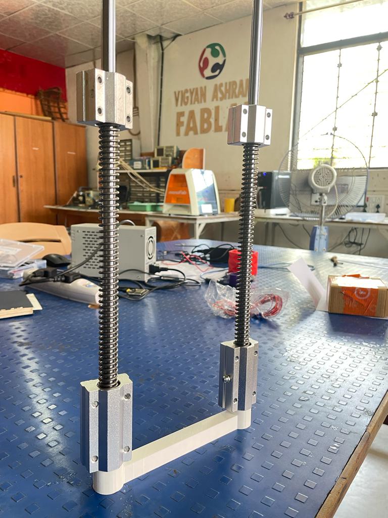
Also fix the 3D Printing prototype of clamps to hold the frame.
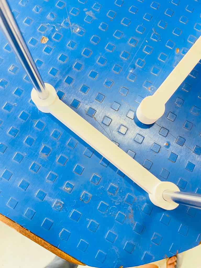
Inserted the springs bearing into the frame to fix them and to take measurements.
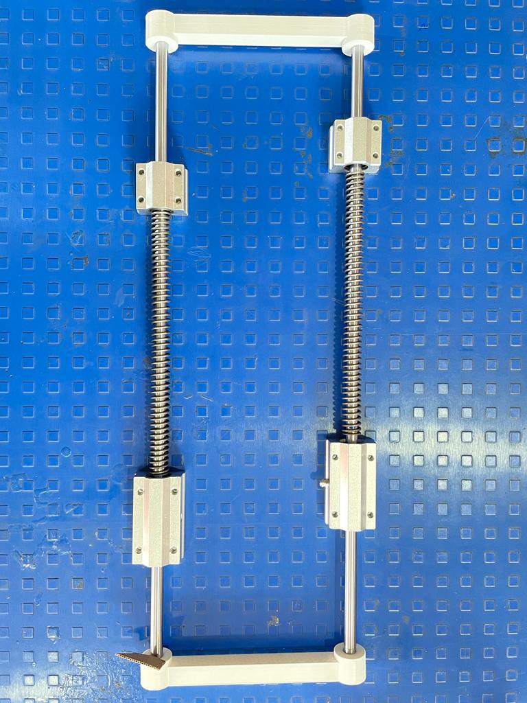
This is how the structure will look.
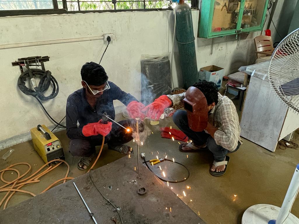
Then used 2 steel washers with high strength to fix the position of the spring on to the rods.
Spring will generate lots of force on the download so, washers needs to be fix very well and for that I have welded it on to steel rods.
Again grind the rod to remove excess weld to maintain uniformity for the linear bearing to move.
I have already printed 2 3D Printed flat plates to mount bag into the suspension frame.
After 3D Printed parts were week, so I replaced them with 5 mm acrylic sheet.
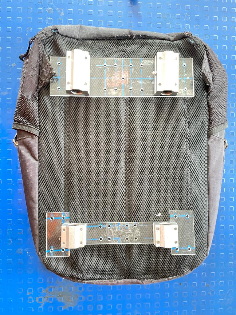
Fixed those laser cut plates to the main frame.
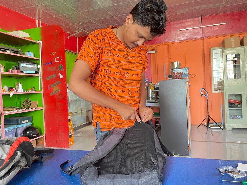
As I am developing the first prototype of the bag so, I have decided to use old unused bag for the experiment.
Removed the straps of the bag as per the design requirement.
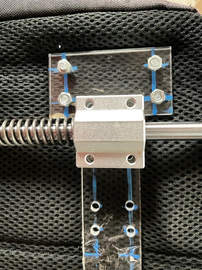
Again used a 5 mm acrylic plate cut through laser to support the suspension frame to the bag.
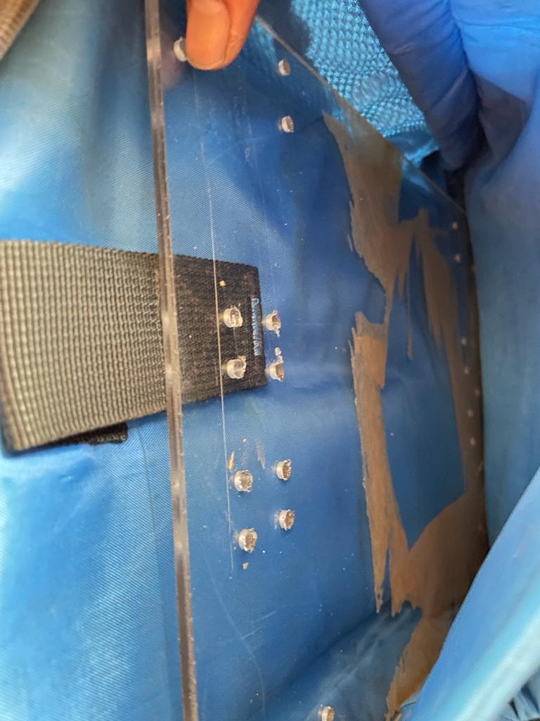
By aligning drills of the inner and outside acrylic plate, I fix them together through M5 bolt and screw.
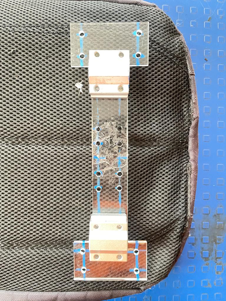
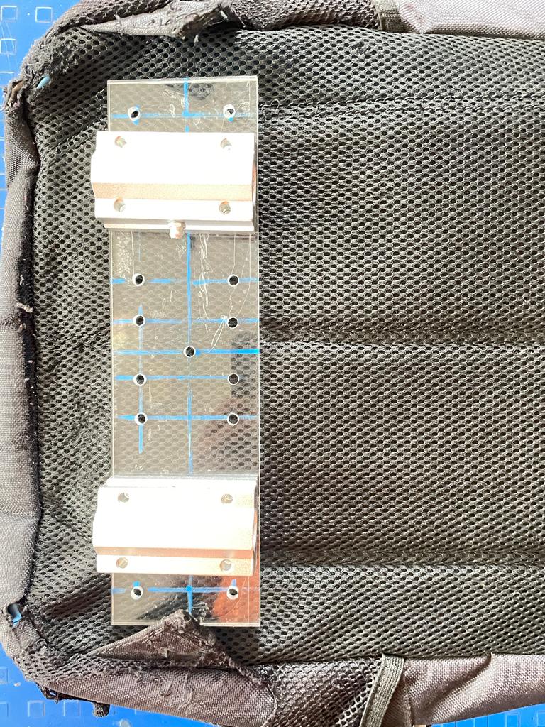
Fitting and fixing of the bag to the frame suspension frame using Nut and bolts.
Used wood bricks as weight to test the suspension of the bag.
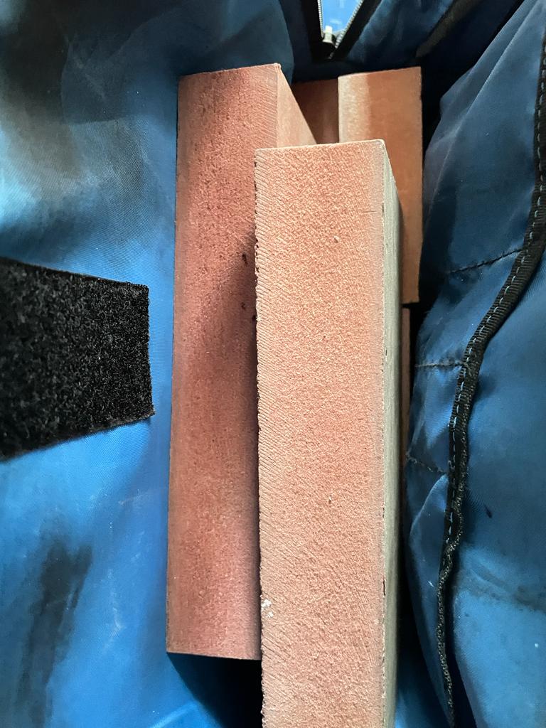
And yes, it works fine suspension is helping the minimize dynamic load produced.
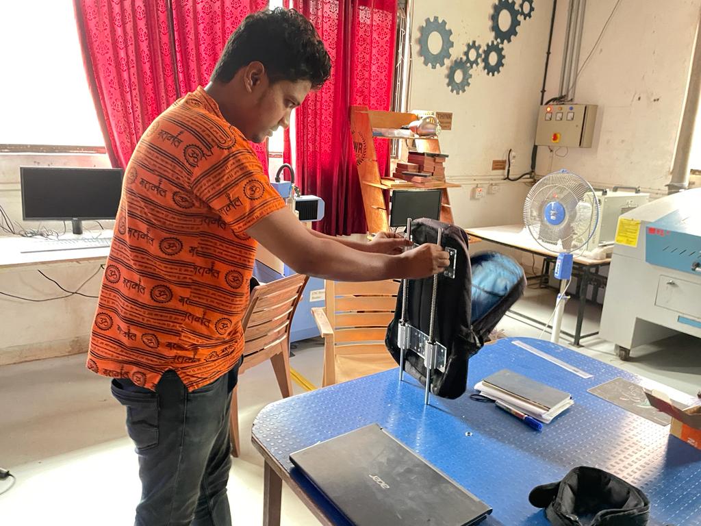
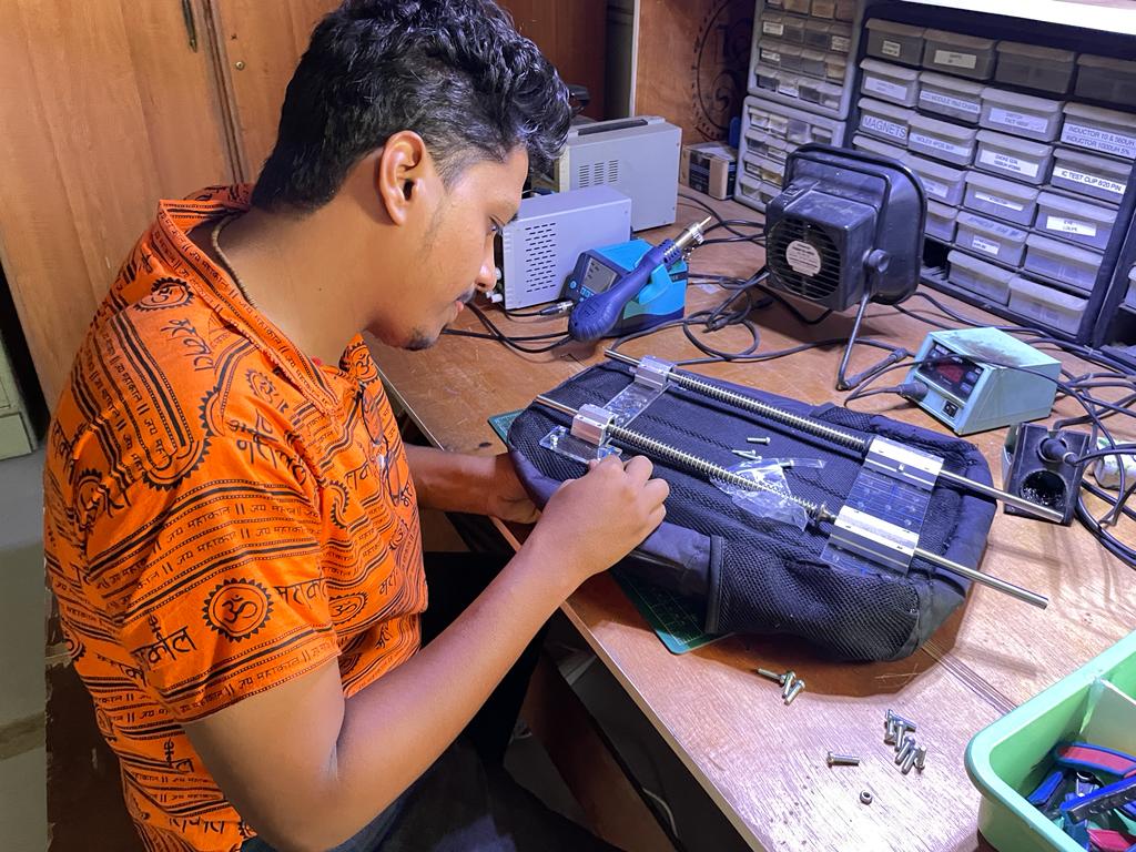
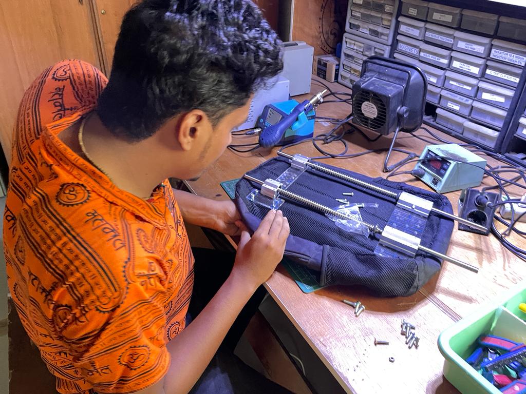
Project Testing and Modifications
Final Project Testing with Electronics.
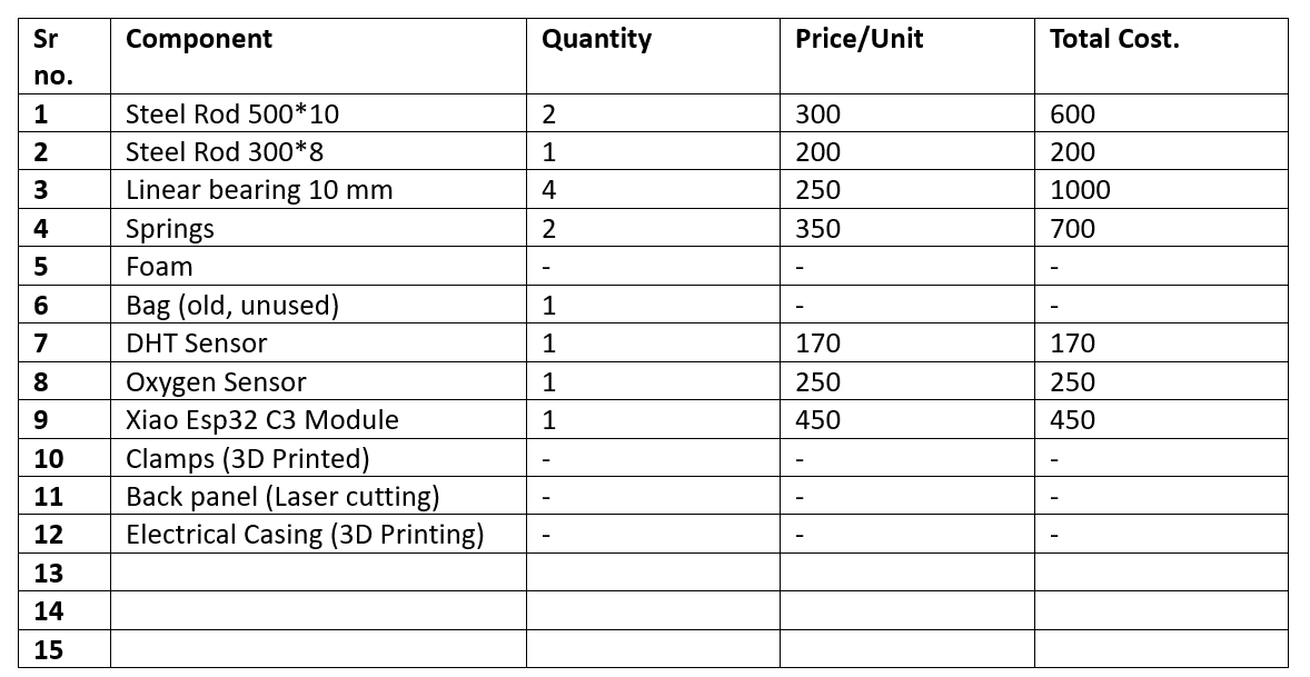
Bill of material
Final Presentation slide
Final Presentation video
Licence Chosen
Smart Suspension Load Backpack © 2023 by Pushkar Suryawanshi is licensed under Attribution-NonCommercial-NoDerivatives 4.0 International. To view a copy of this license, visit http://creativecommons.org/licenses/by-nc-nd/4.0/ I have included the license details in the footer of the final project page, as well as in plain text below the project name on the final project presentation slide, as illustrated below.
Original Design files
Acknowledgement
I would like to extend my heartfelt gratitude to Professor Neil and his esteemed team, as well as the esteemed individuals at Vigyan Ashram. I express my sincere appreciation to Mr. Yogesh Kulkarni, the Director, and Mr. Ranajeet Shanbhag, the Deputy Director. I am immensely grateful to my instructors at Fab Academy, Mr. Suhas Labade sir and Mr. Kishore Gaikwad sir, for their valuable guidance. I also wish to acknowledge the support and collaboration of my colleague, Mr. Sanjay Surage. Furthermore, I would like to commend the efforts of Shankar Sai, a fellow at Vigyan Ashram Fab Lab, and the contributions of Mr. Sumedh Yewale, Mr. Mahesh Shinde, Mr. Vaibhav Rahane, Ms. Gayatri, and Mr. Ghanshyam Bande from the DIC team, who provided invaluable assistance throughout my Fab Academy assignments and final project.