Output Devices
Week Assignement summary
This week, I have understood and used different output devices with a microcontroller board also in the group assignment we did calculate power consumption by different output devices.
Here i have documented all of my works with different softwares like eagle, Mods, VPanel and production of my second PCB.
Group Assignement
In this week’s group assignments, we have to go through different output devices, and also calculate their operating current and voltage in order to calculate the power consumption of those output devices.
I have gone through different output devices like LEDs, Buzzers, OLED Displays, LCD Displays, Servomotor, and toy motors.
Power consumption of DC Motor
Current
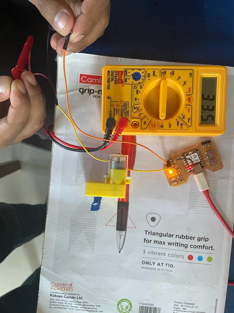
Voltage
Power consumption of DC toy Motor = V*I= 9.4*0.03= 0.282 watts
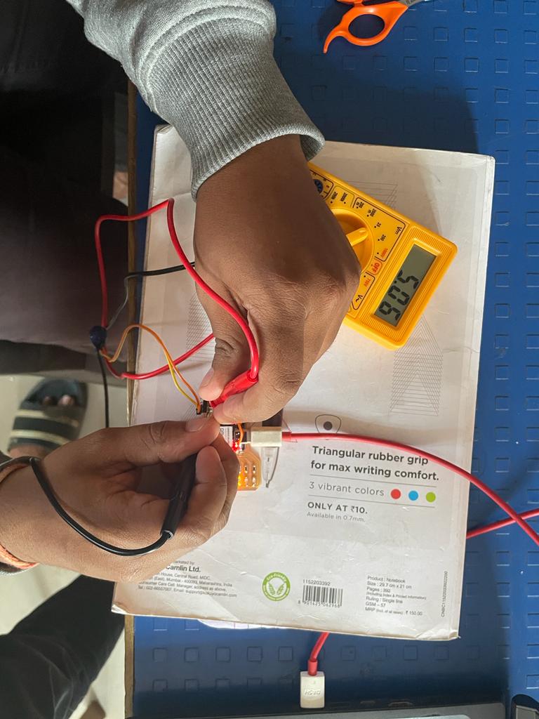
Power consumption of LCD I2c Display
Current
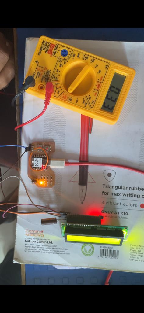
Voltage
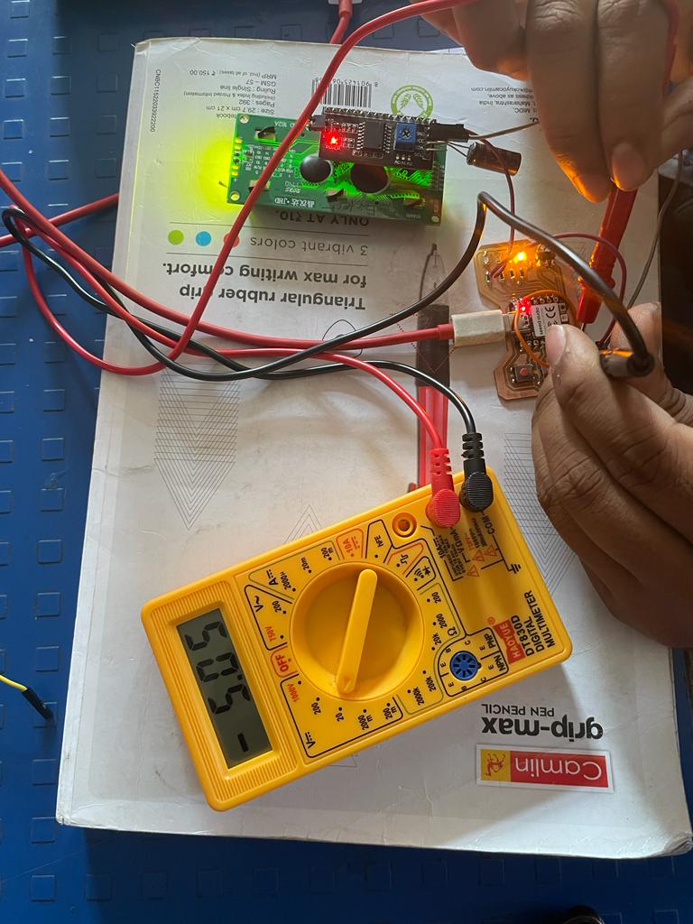
Power consumption of lcd i2c = V*I= 5.05*0.035= 0.176 watts
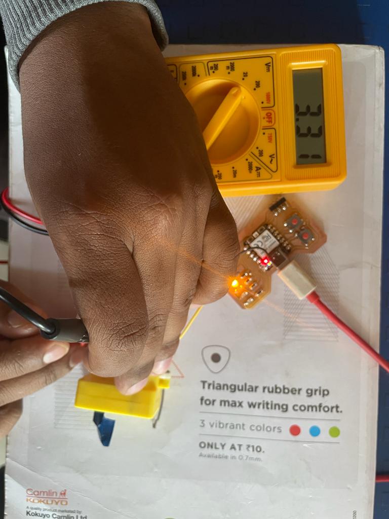
Power consumption of Buzzer
Voltage
Power consumption of Buzzer = V*I= 5.07*0.020= 0.101 watts
Power consumption of LED
Voltage
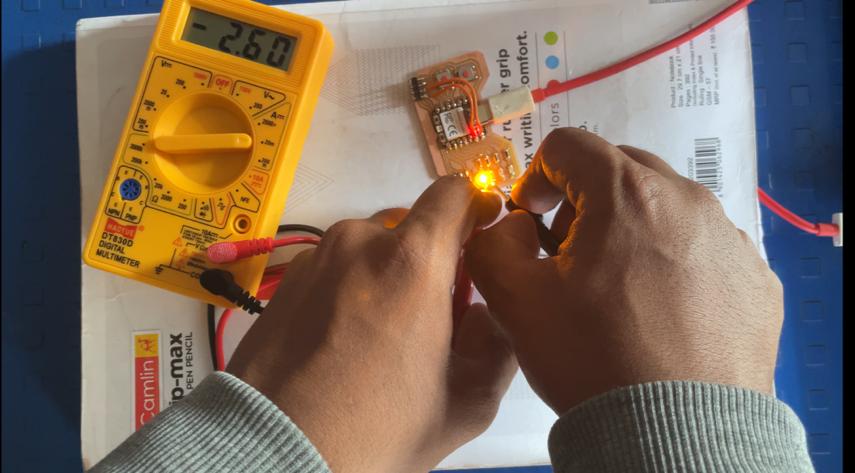
Power consumption of 1206 SMD = V*I= 2.018*0.025= 0.054 watts
Individual Assignement
Design and production of the development board
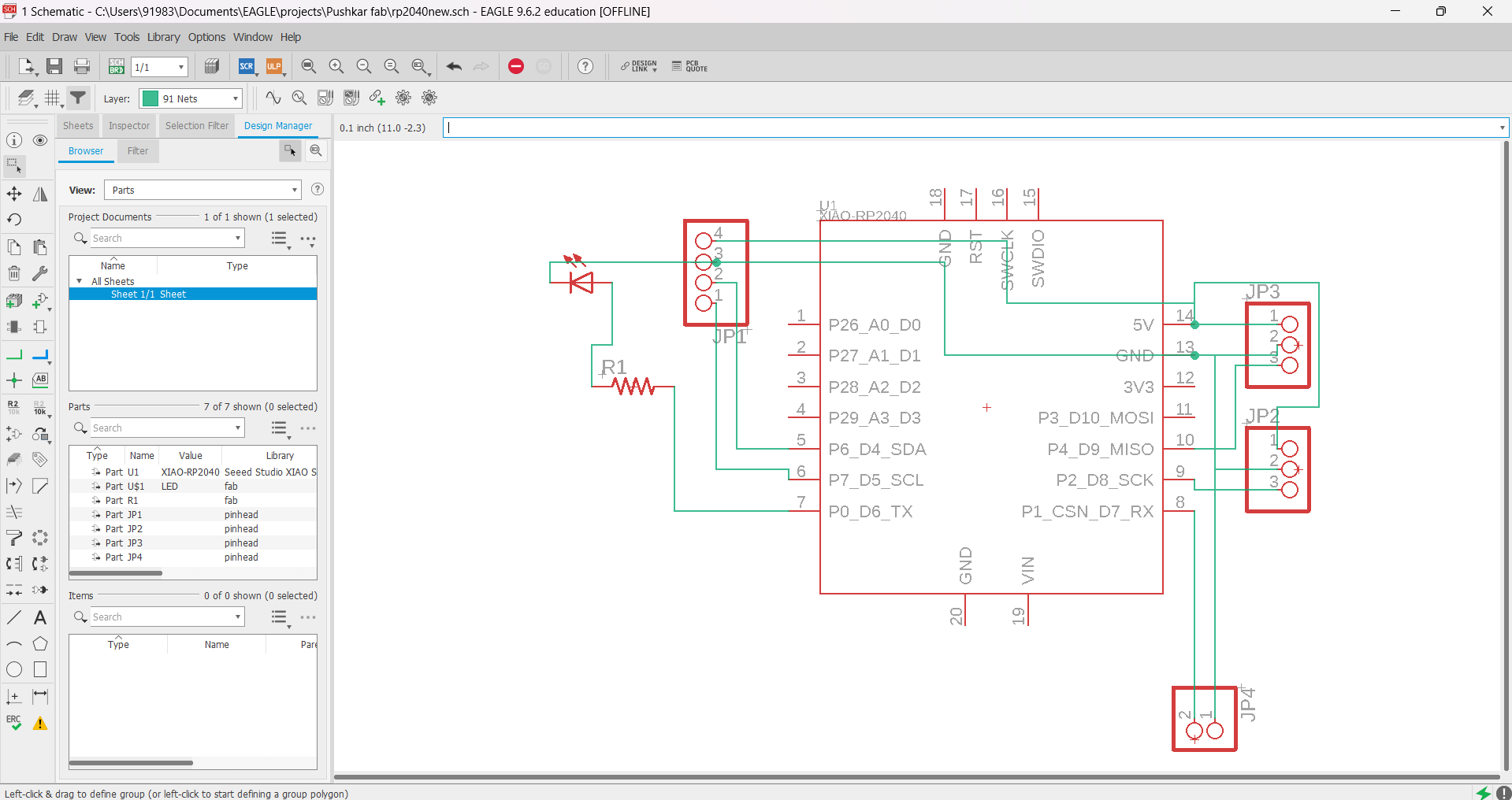
Board Schematic
Used Xiao Rp2040 microcontroller. Also soldered SMD Led with 100-ohm resistor within it. Also provided pinheaded for I2C and PWM signals.
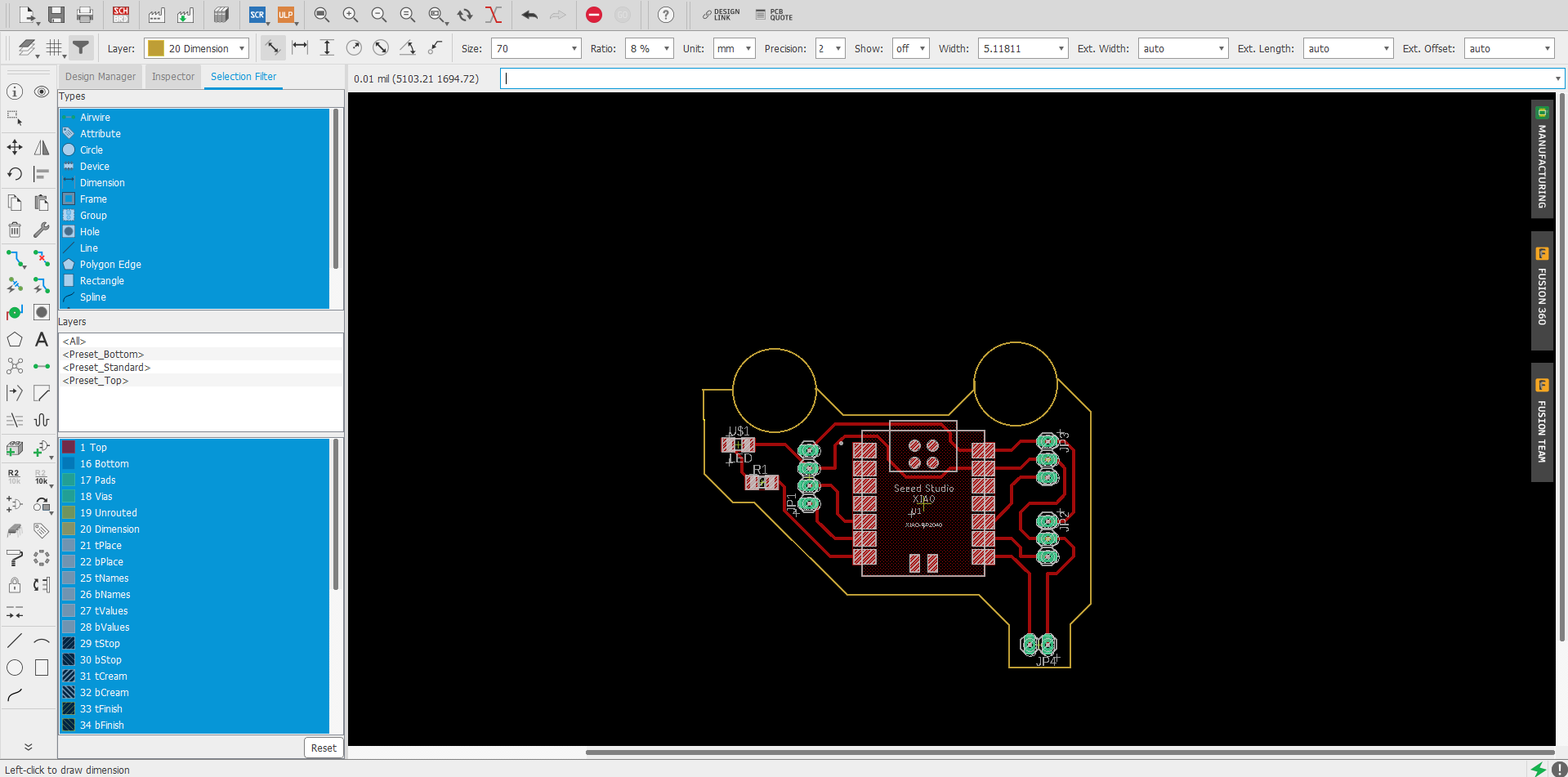
Board Design
After Doing ERC Check generated a board for the above schematic and arranged all the components to give a design to the board like a vehicle.
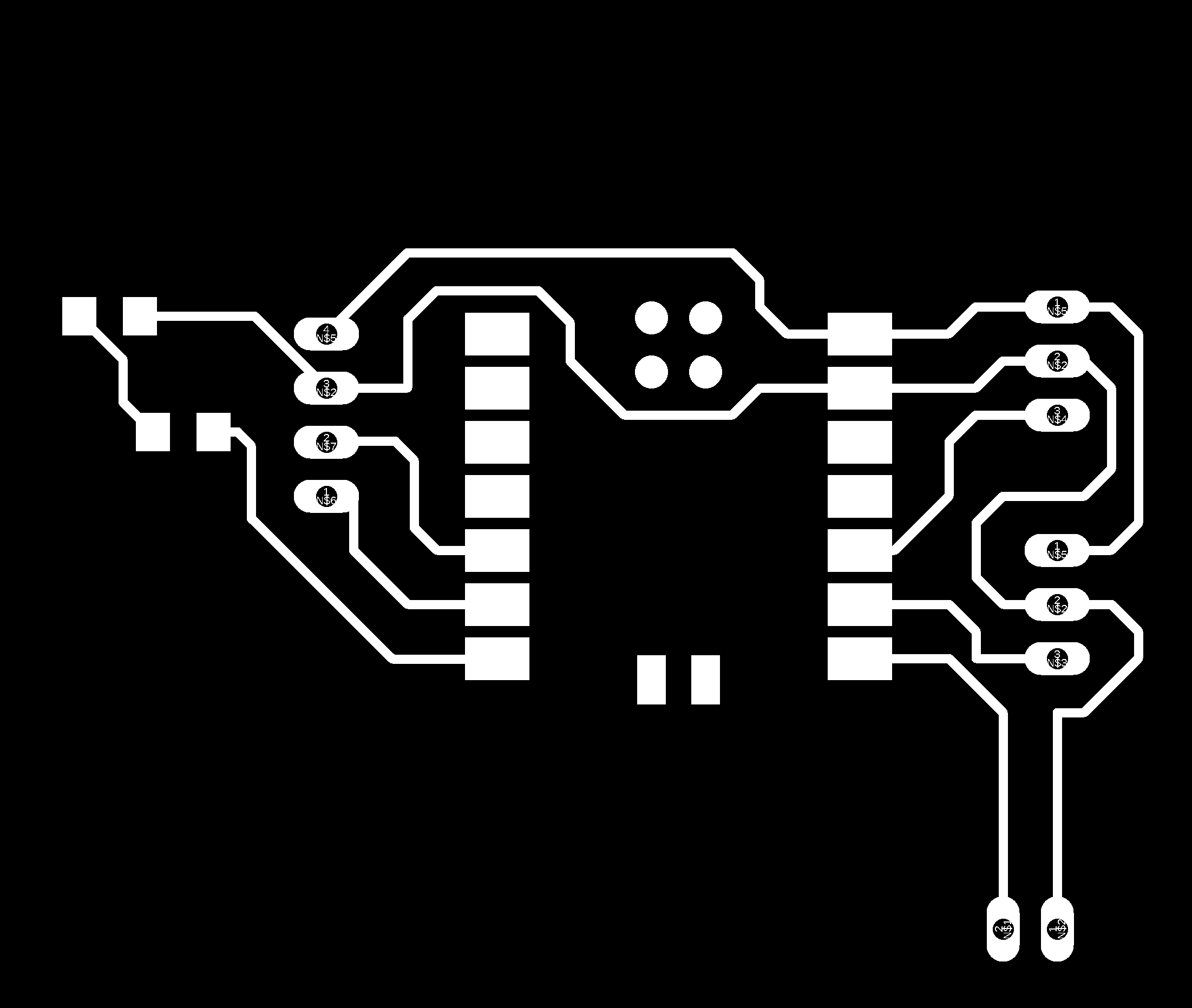
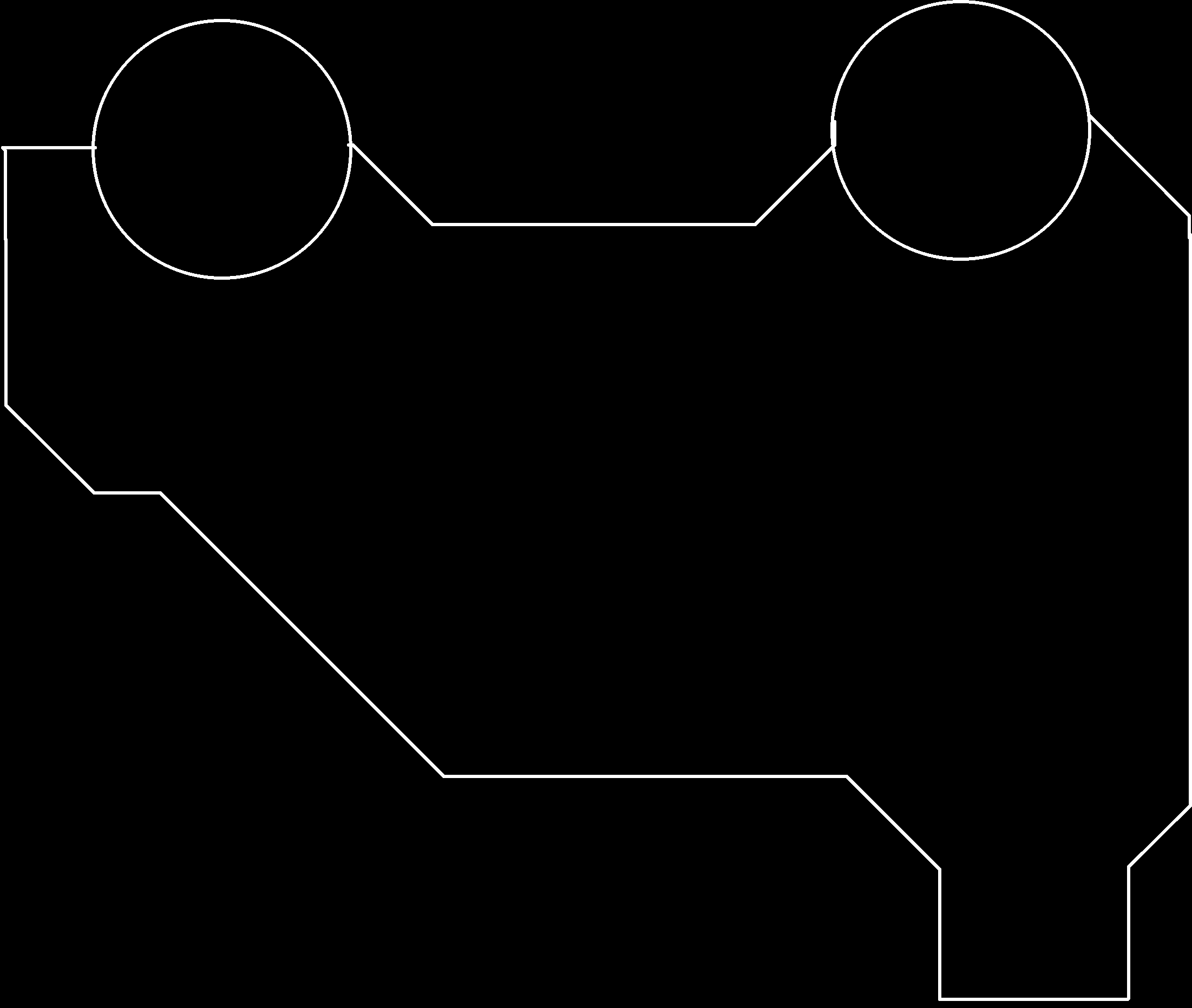
.png Gneration
After doing DRC check downloaded the .png file for both traces and border..
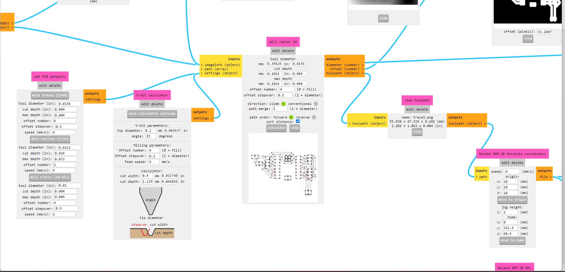
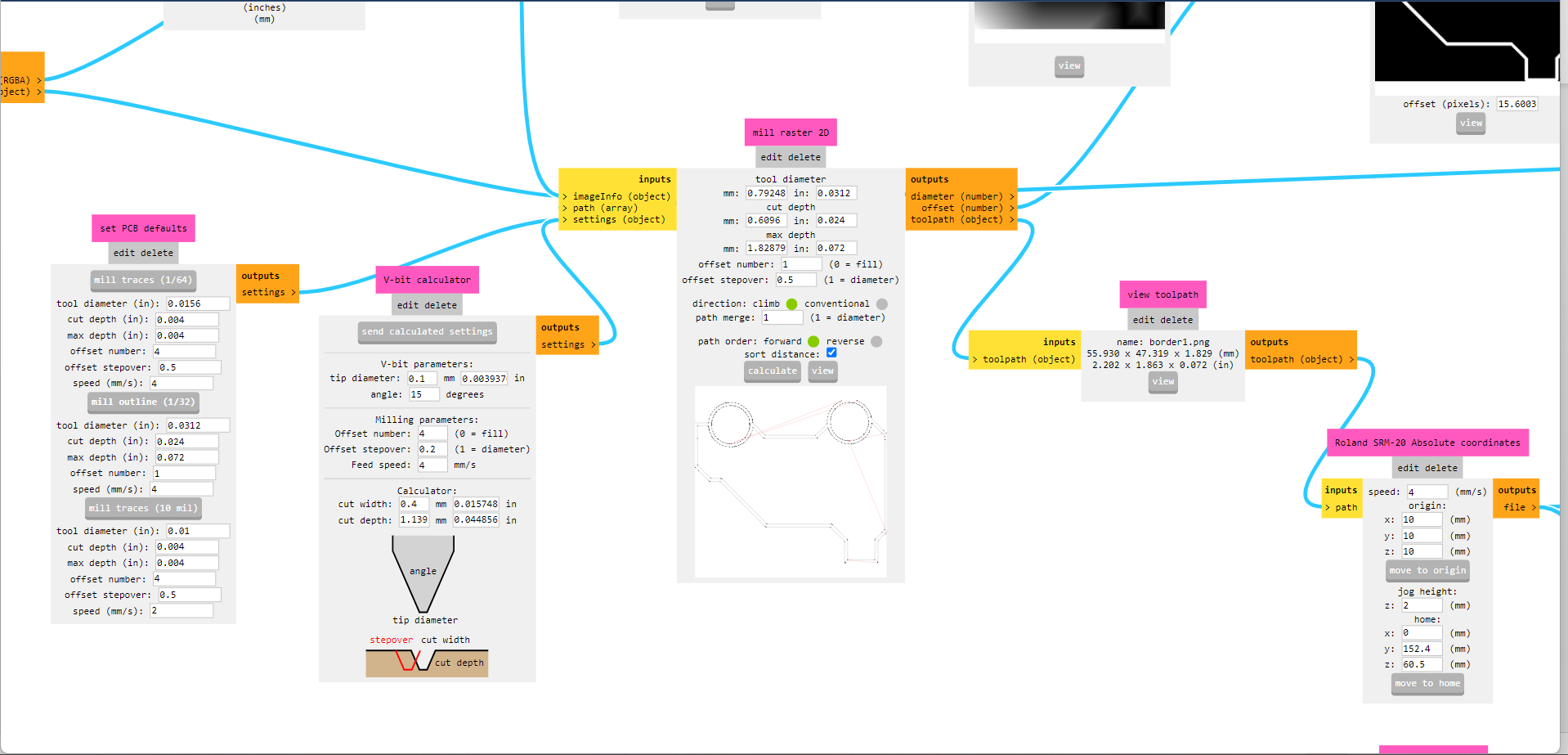
Community Mods
Inserted png files to community mods by selecting tool diameter and home position and downloaded tool path for milling.
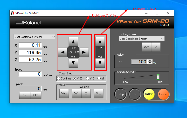
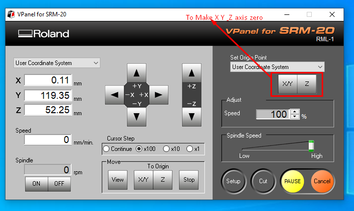
V Panal
VPanel is cam software used to operate SRM20 milling machine.
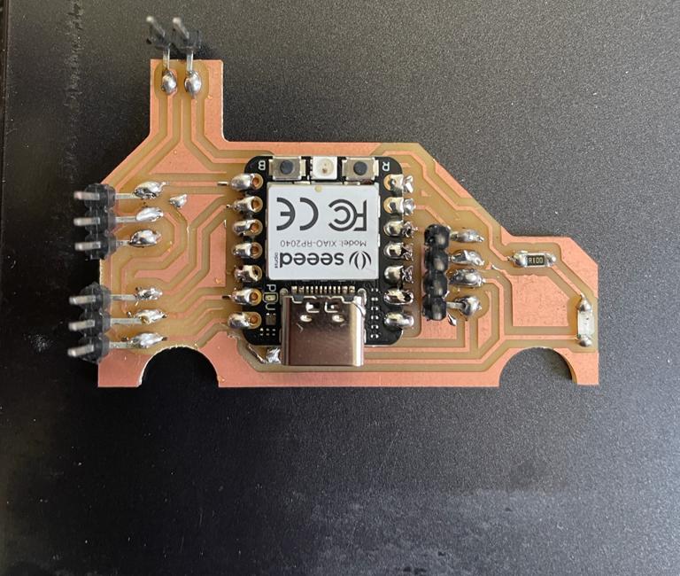
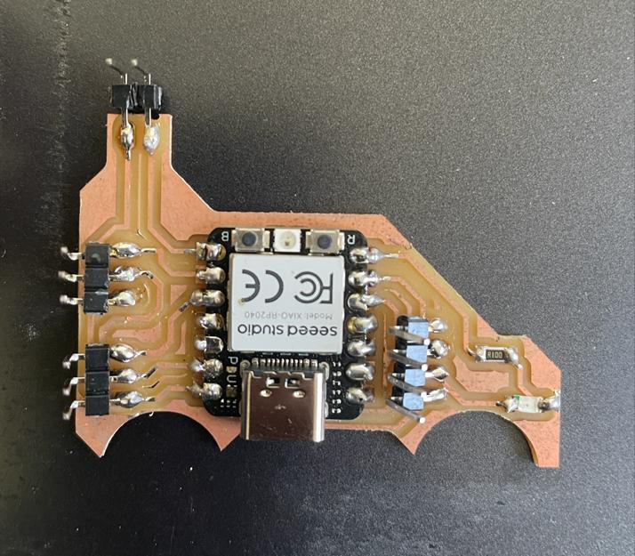
Final Board with Soldered Components.
Used Xiao Rp2040 microcontroller. Also soldered SMD Led with 100-ohm resistor within it. Also provided pinheaded for I2C and PWM signals.
Programming
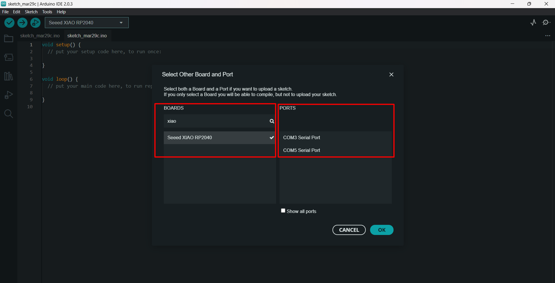
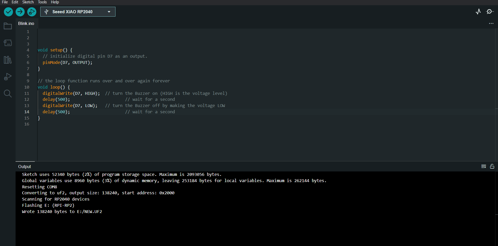
Arduino IDE
Since i am using Xiao rp2040 microcontoller which supports micropython as well as c+ also, so i downloaded libaray for xiao rp2040 for arduino ide which allowed me to use arduino ide to program xiao rp2040.
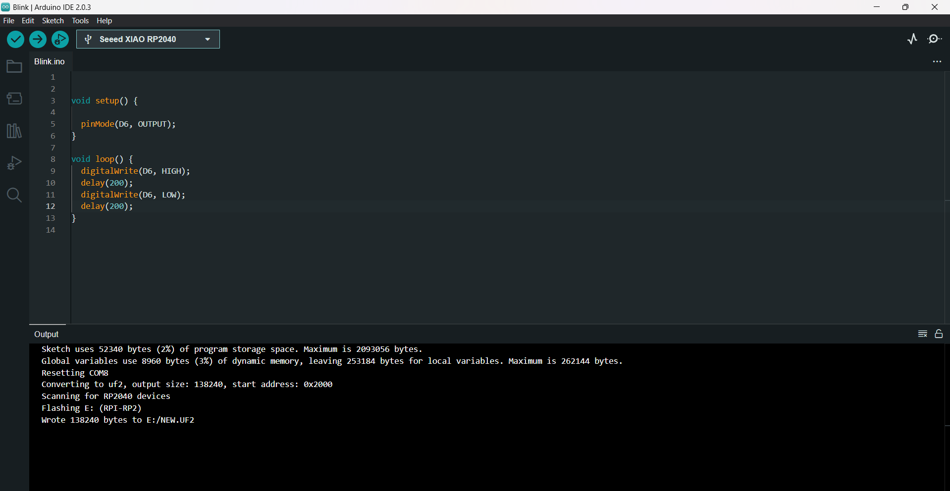
LED Blinking
Features :-
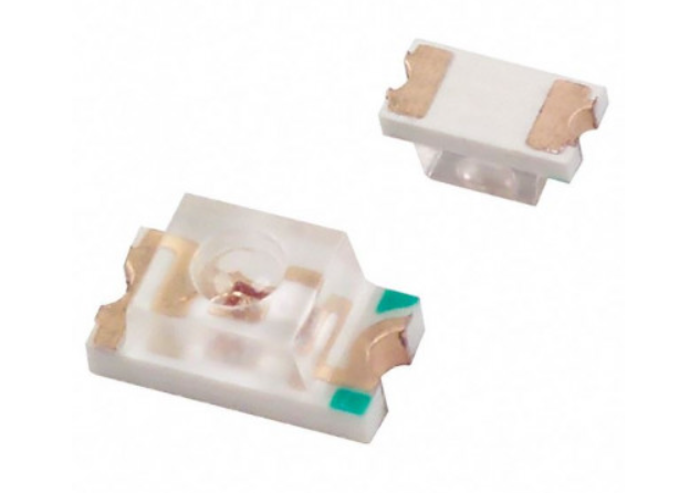
Type - Surface Mount 5730 package LED
Feature –
Industry Standard 5730 Package • R ohms Compliant • Small Package and Foo print X - (C) Cool White, (N) Natural White, (W) Warm White • Wide Viewing Angle Ideal for Lighting and Ba lighting Application Bivar Surface Mount 5730 package LED may be used in nearly any lighting or backlighting application.
These 0. 5 Watt SMD LEDs have a minimum CRI Value of 80 and are available in 3 color temperatures to meet any illumination needs: Cool, Neutral, and Warm White.
The SM5730 Series is conveniently packaged in standard tape and reels for pick and place assemblies. Part Number SM5730UWDC05SM57.
Programming
Fixed 1206 SMD led to the PCB with 100 ohm resitor to pin no D6, and programmed it blink continuously.
Led is fixed between pin no D6 and ground
Final Video
Servo Motor
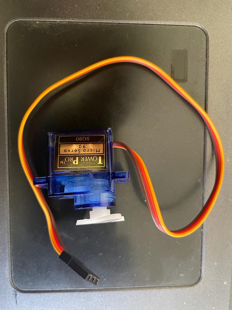
Part Name – SG90,Type – Micro Servo
Features –
SG90 9 g Micro Servo Tiny and lightweight with high output power.
Servo can rotate approximately 180 degrees (90 in each direction) and works just like the standard kinds but smaller.
You can use any servo code, hardware, or library to control these servos.
Good for beginners who want to make stuff move without building a motor controller with feedback & gear box, especially since it will fit in small places.
It comes with 3 horns (arms) and hardware.
Weight: 9 g
Dimension: 22.2 x 11.8 x 31 mm approx.
Stall torque: 1.8 kgf·cm
Operating speed: 0.1 s/60 degree
Working Principle of Servo Motor
Servo motor can rorate from 0-180 degree, and the degree of rotation can be controlled by electrical pulse with some width.
motor checks the pulse at every 20 millisecond. The pulse of 1 ms width can rotate the servo to 0 degrees, 1.5ms can rotate it 90 degrees and 2 ms pulse rotate it 180 degree.
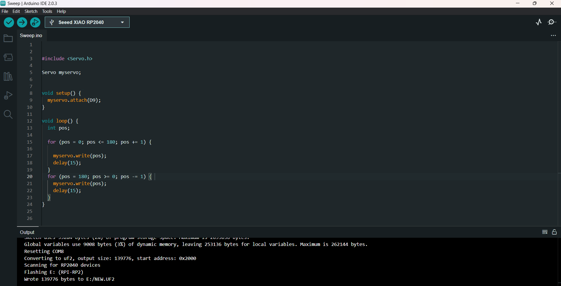
Programming
i have used 180 degree rotational servo motor, which conatin 3 pins Digital pin, vcc and ground
i have attached digital pin to D9, 5 v vcc and ground
A 1mSec pulse positions the shaft at 0 degrees. A 1.5mSec pulse positions the shaft at 90 degrees. A 2mSec pulse positions the shaft at 180 degrees. Pulses with values between these can be used to position the shaft arbitrarily.
Final Video
Buzzer
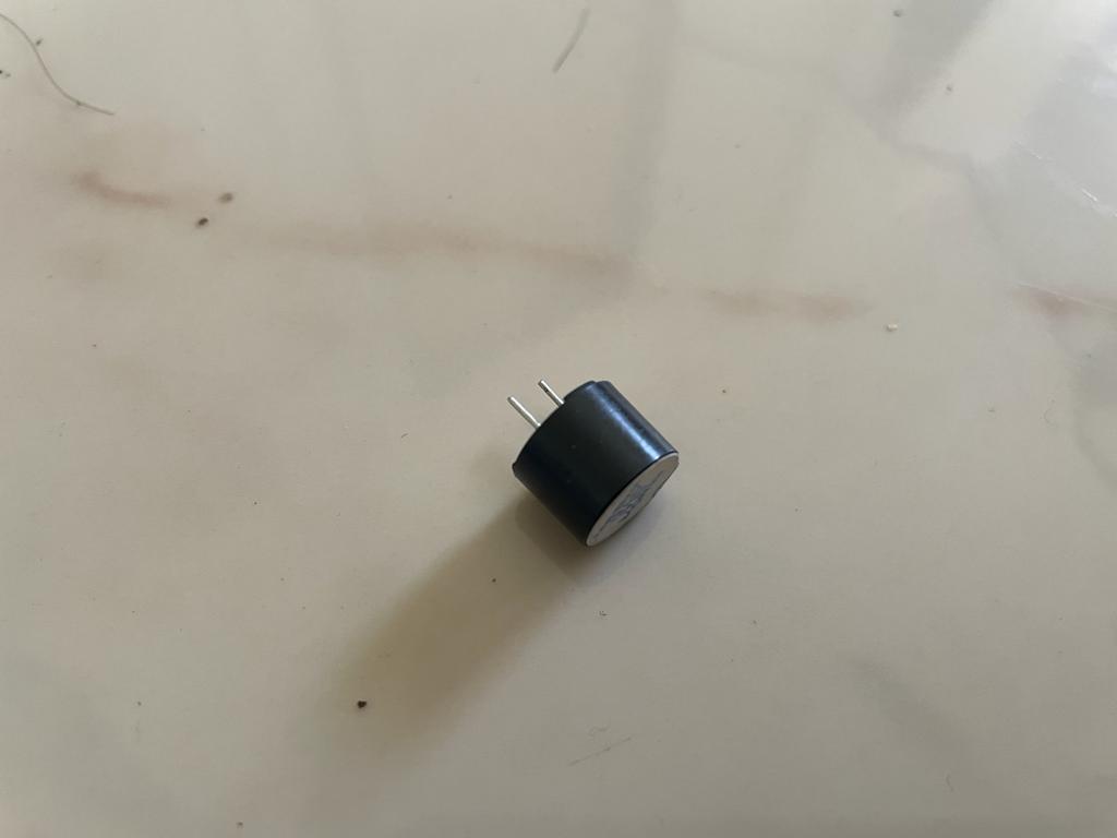
SPecifications: -
Rated Voltage: 6V DC
Operating Voltage: 4 to 8V DC
Rated Current* : ≤30mA
Sound Output at 10cm* : ≥85dB
Resonant Frequency: 2300 ±300Hz
Tone: Continuous
Operating Temperature : -25°C to +80°C
Storage Temperature : -30°C to +85°C
Weight: 2g
Working Principle of Buzzer
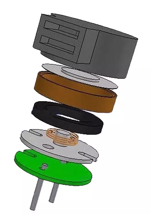
Electromagnetic buzzer consists of an oscillator, solenoid coil, magnet, vibration diaphragm, housing, and other components. When the power is turned on, the audio signal current produced by the oscillator flows through the solenoid coil, creating a magnetic field. Through the interaction of the solenoid coil and the magnet, the vibration diaphragm vibrates periodically, producing sound.
Programming
Used buzzer with sound at >85dB and tried to controlled it wih rp2040
Attach buzzer to digital pin D7 and ground and tried to On and OFF the buzzer
Final Video
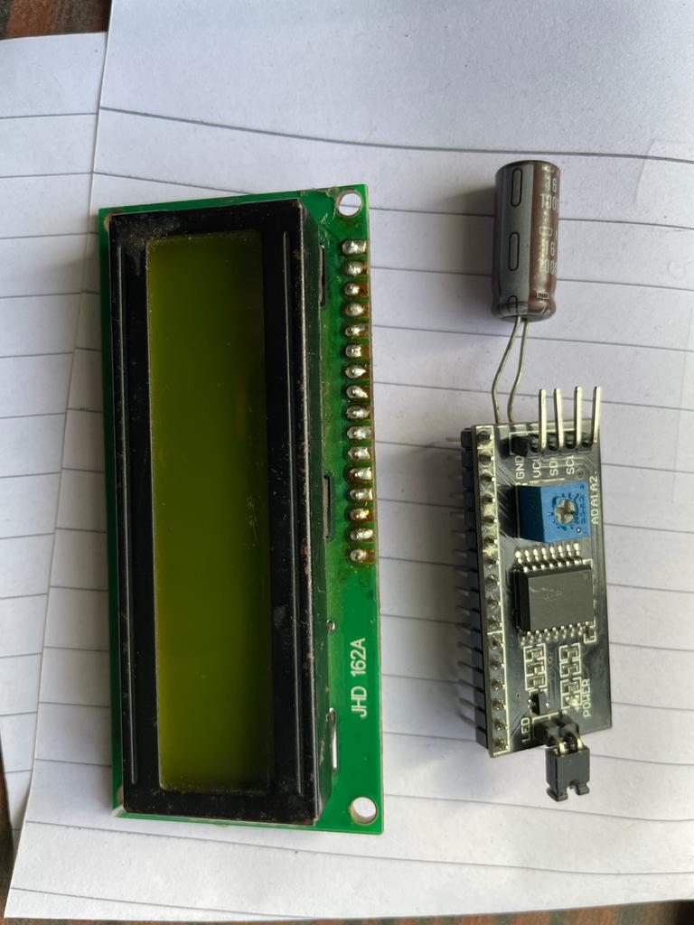
LCD i2c Display
A typical I2C LCD display consists of an HD44780-based character LCD display and an I2C LCD adapter.
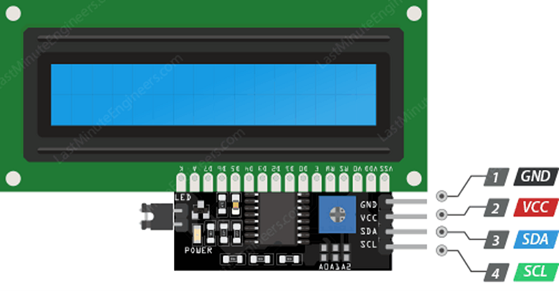
Pin Details
Specifications:-
1.Compatible with Arduino/Genuino UNO, Mega, Micro, Nano, Mini
I2C Address: 0x20-0x27(0x20 default)
Back lit (Blue with white char color)
Supply voltage: 5V
Interface: I2C/TWI x1,Gadgeteer interface x2
Adjustable contrast
Size: 82 x 35 x 18 mm (3.2×1.4×0.7 in)
White text on the Blue background
Interface Address: 0x27
Character Color: White
Backlight: Blue
Supply voltage: 5V.
Working Principle of LCD i2c Display.
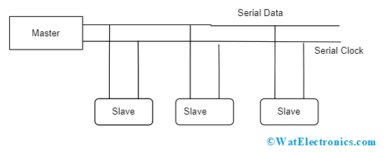
The I2C communication protocol uses open drain lines, namely Serial Data (SDA) and Serial Clock (SCL). These lines are initially pulled high, and the protocol operates in two modes: Master and Slave. Each bit transferred on the serial data line is synchronized by a high-to-low pulse for every clock signal received on the serial clock. The SDA line remains unchanged when the SCL is high and only changes when the SCL is low. Since SDA and SCL are open-drain lines, they require a pull-up resistor to maintain a high state due to the devices on the bus being in an active low state.
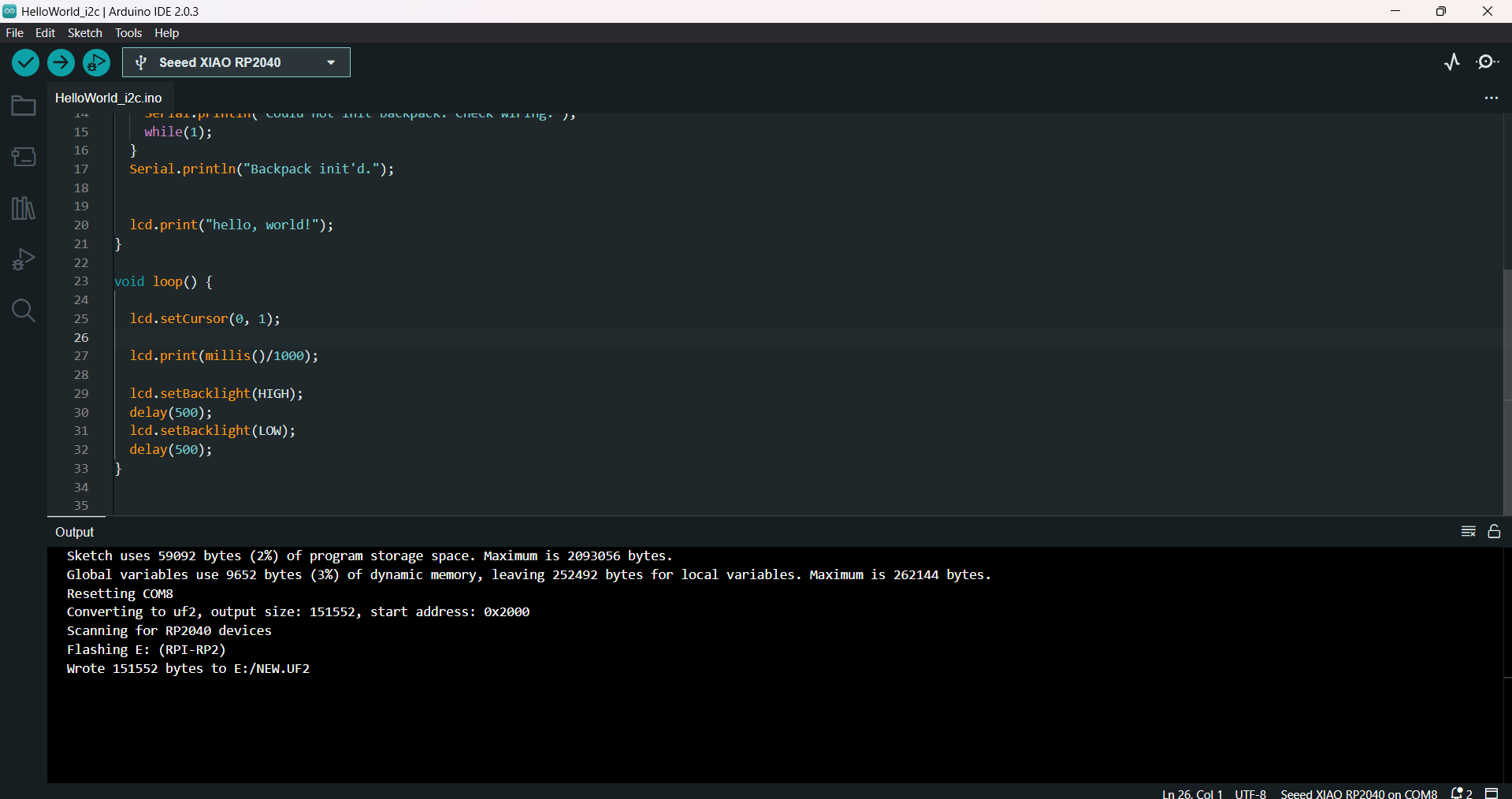
Program
LCD requires I2C Connection which contain vcc, ground, SDA, SCL
Connected LCD display to micontroller using i2c adapter.
tried to print "Hello World" with LCD display
Final Video
Learning from this week
1) Can able to use Different Output devices and their programming with arduino ide.
2) able to do soldering of SMD Components
3) Become more familier with electronics
What Went Well
A) Group Assignment went well, able to calculate power consumption..
B) Understood pinout structures of microcontroller and output devices.
Problem Faced
A) Traces got damaged during the soldering process, which caused I2C connection not to work.
B) Faced Issue with desoldering of misplaced components.
C) Used bottom sided ground connection for PCB and faced issues