Wild Card Week.
Week 15 Assignment summary
For this week, I tried to work with plasma cutter and Embroidery Machine. I have able use these machines along with their cam software.
I have briefly documented all of my work with Designing , Generating Tool path and other things.
Objective Of the Week
Design and produce something with a digital fabrication process (incorporating computer-aided design and manufacturing) not covered in another assignment, document the requirements that your assignment meets and include everything necessary to reproduce it.
We have a Digital sewing machine and plasma cutter also, so I used both of these digital manufacturing processes to produce or fabricate something.
Embroidery Machine.
We have an embroidery machine at our Fab Lab Vigyan Ashram, and I want to print my company logo on a T-shirt for that as an initial trial, I print it on a cotton part.
Machine used
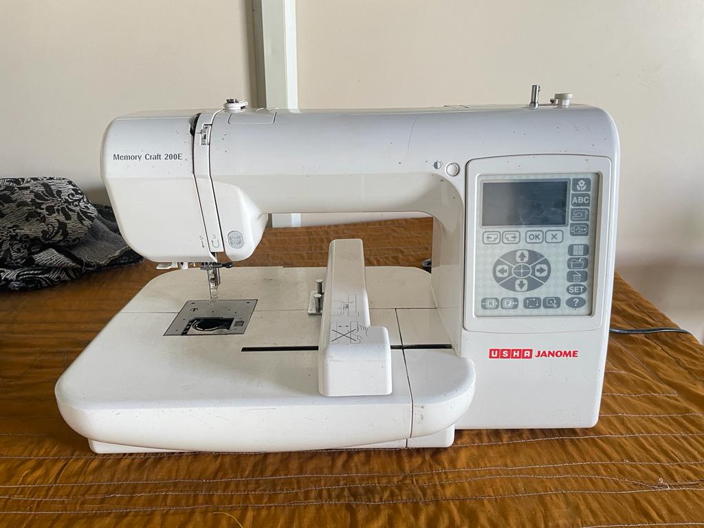
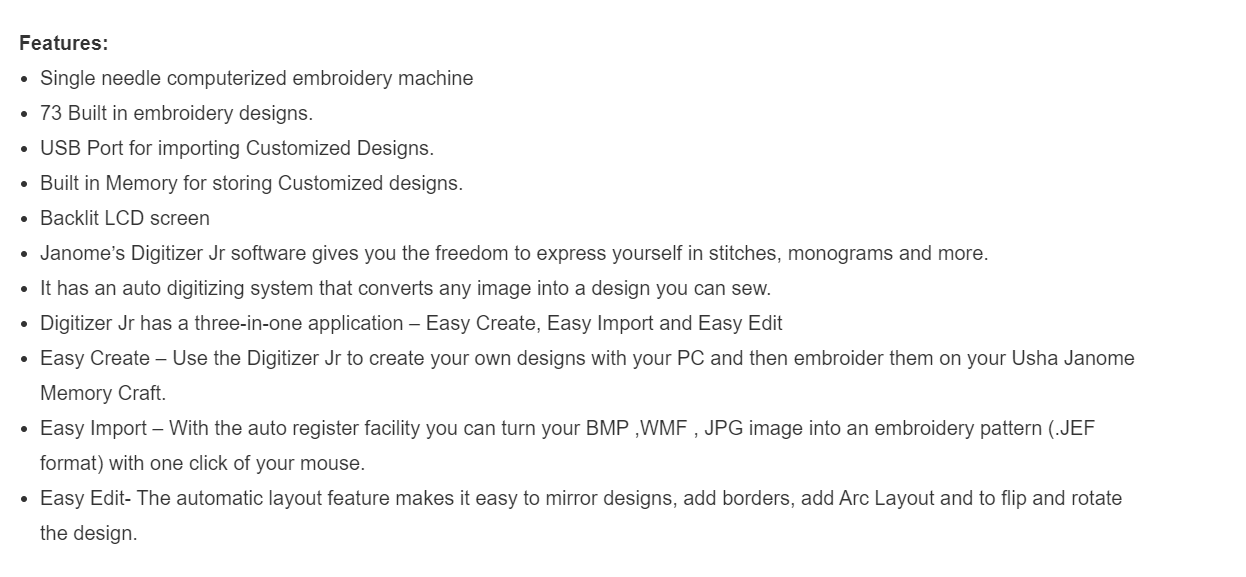
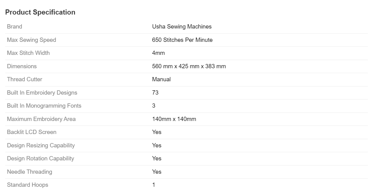
A computerized embroidery machine, the Memory Craft 200 E is ideal for embroidering up to 140 X 140 mm designs. Multiple font sizes are available for each font to design monograms and a USB Port helps import customized designs. Along with this, the free Digitizer Jr V5 software allows one to edit existing designs and make select custom designs. 73 built-in designs and a backlit LCD screen help scale up one’s creativity.
Material Used
Used cotton plus polyester material for the artwork. We also used canvas paper behind cotton material to maintain its uniformity while the sewing process.
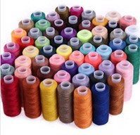
Also have used regular sewing threads for the process and used three colors Black, White, and blue for the artwork.
Working steps
Design

Cam Software
Used digitizer cam software from Janome. Can be used by downloading it.
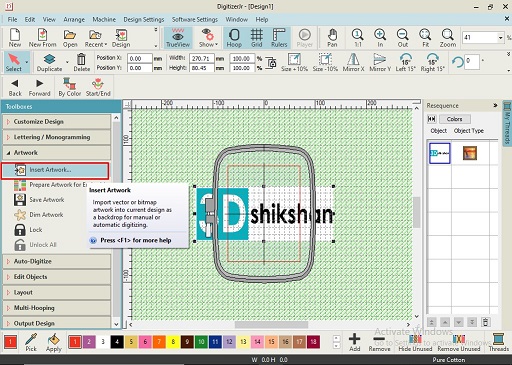
From home screen of the software is look like this.
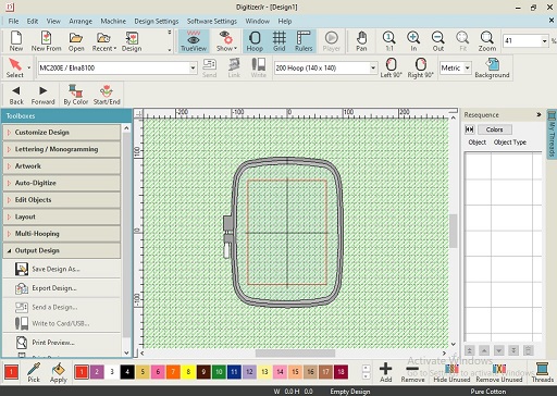
Imported a file as per my requirement, supported file format for the image is .png file format.
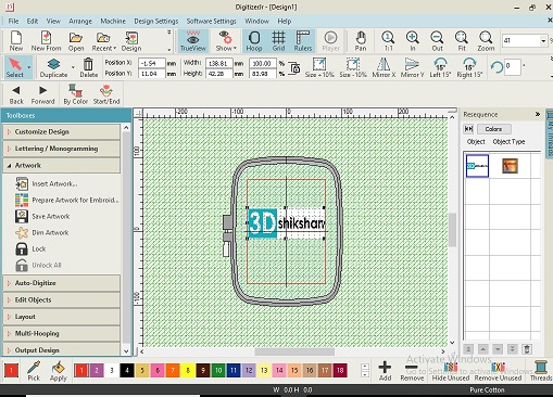
After uploading the images, did some resizing and rearrangement to ensure that design must be under canvas holder.
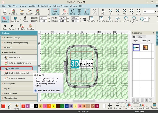
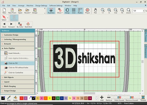
Then by clicking on the Click to fill option under auto digitizer.
Then by increasing the value percent of cartoon processing artwork for the embroidery machining process.
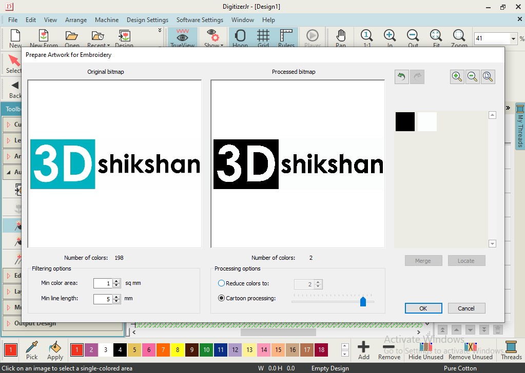
After completing these basic processes, I got my final file ready for the machining process.
Processing
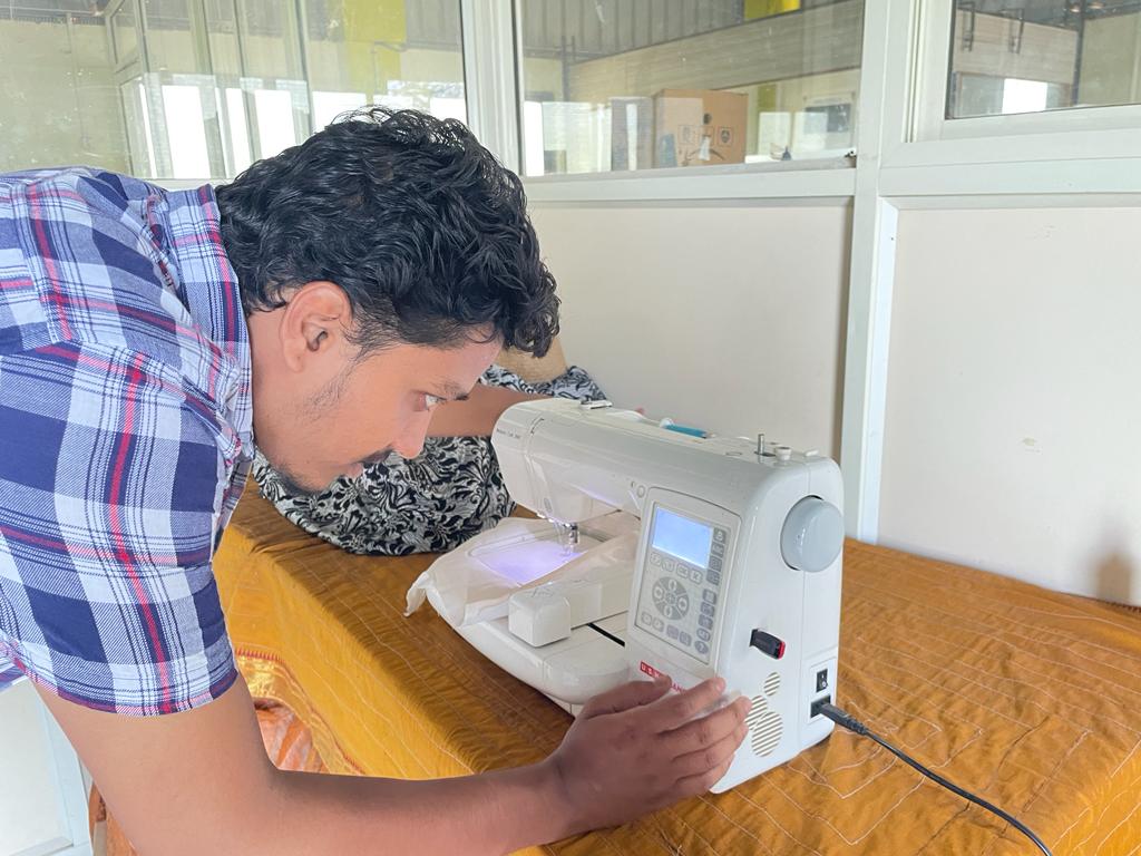
We have a USHA Janome Sewing machine at our Fab lab at Vigyan Ashram.
Then we selected cotton fabric material with canvas attached from the backside.
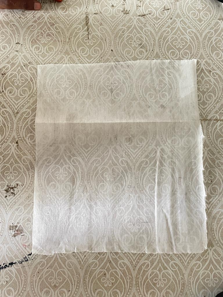
Attached canvas to the cotton material from the backside and clamp it to the to maintain its uniformity.
Ms. Priyanka Madam instructed us how to use machine and gave training for the same.
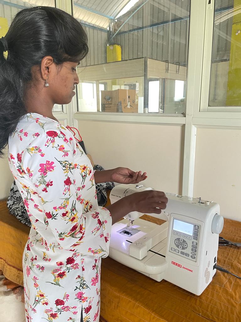
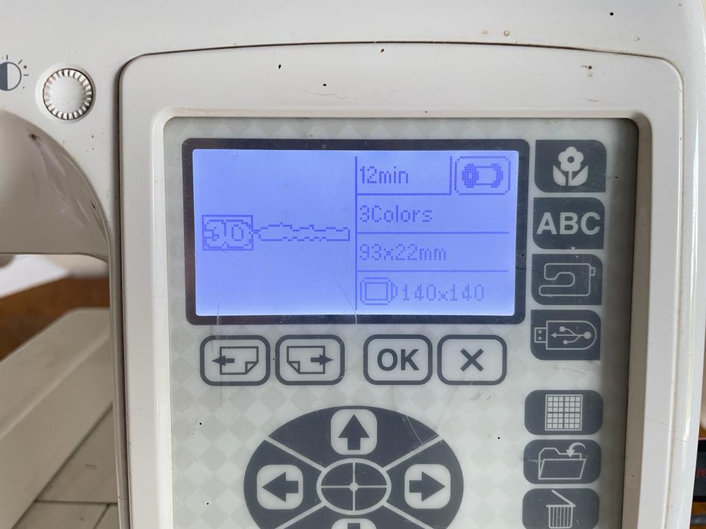
Machine has display and buttons along with that. Then through USB Transferred prepared file to the machine and selected require file..
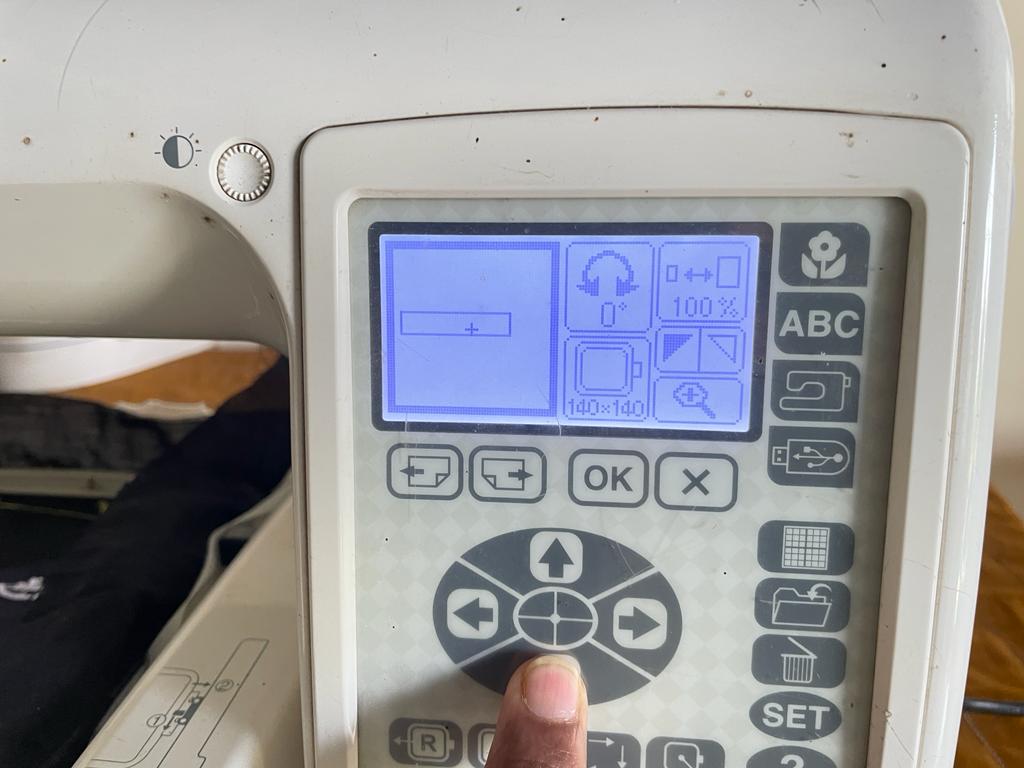
Set up home position and selected a specific are from the design as I wat multiple threads for the design.
After doing all the basic setup I can clearly able see my design on the display and ready to start with it.
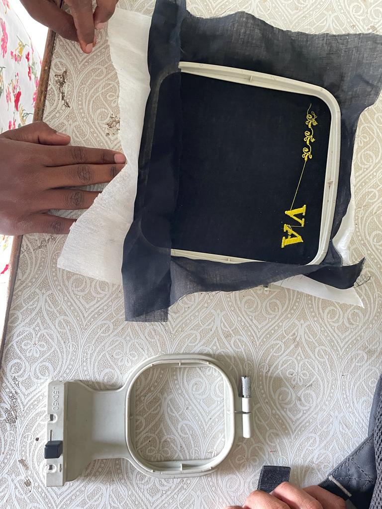
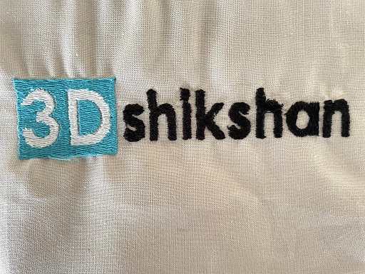
Final Output
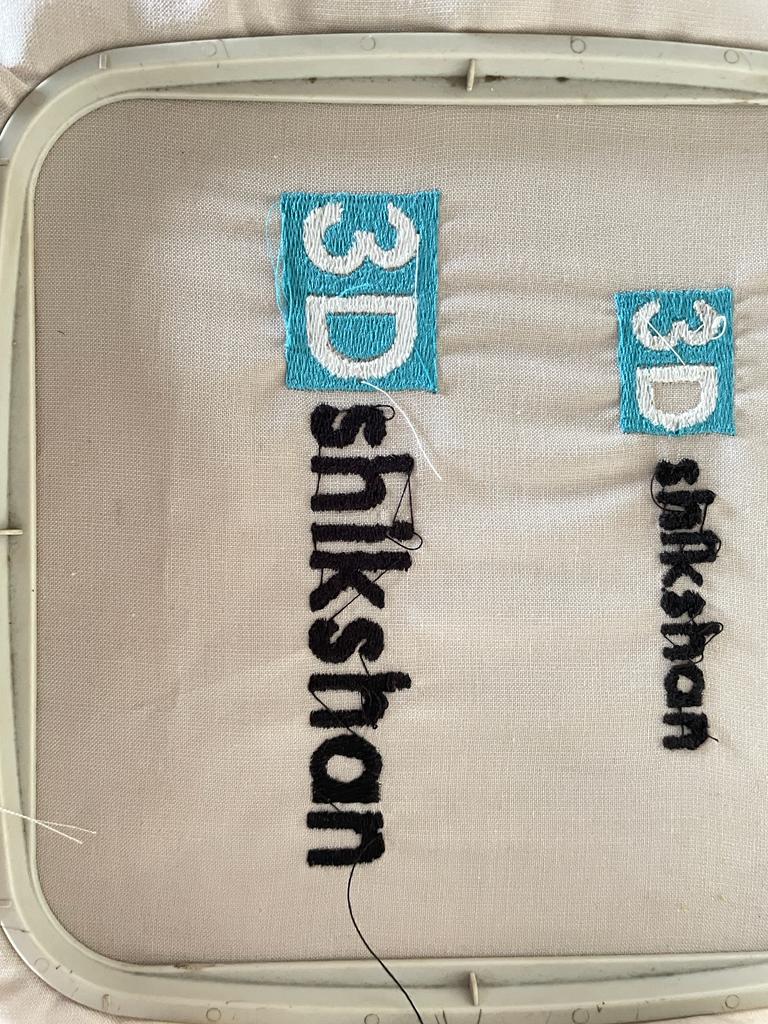
I did two trails for the same design as in the first design I took text size too small which beyond the capability of the machine, so by increasing the font size of text I got final output.
Video
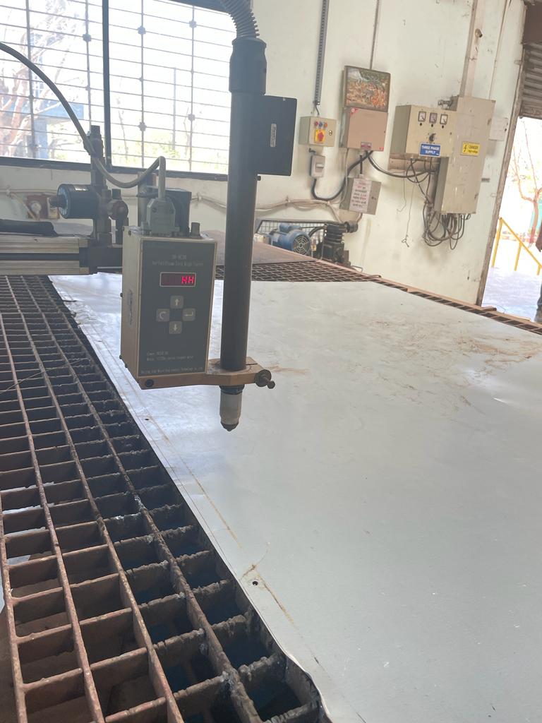
Plasma Cutting
Plasma cutting is a process that cuts through electrically conductive materials by means of an accelerated jet of hot plasma. Typical materials cut with a plasma torch include steel, stainless steel, aluminium, brass, and copper, although other conductive metals may be cut as well. Plasma cutting is often used in fabrication shops, automotive repair and restoration, industrial construction, and salvage and scrapping operations. Due to the high speed and precision cuts combined with low cost, plasma cutting sees widespread use from large-scale industrial computer numerical control (CNC) applications down to small hobbyist shops.
Referance is taken from wikipedia
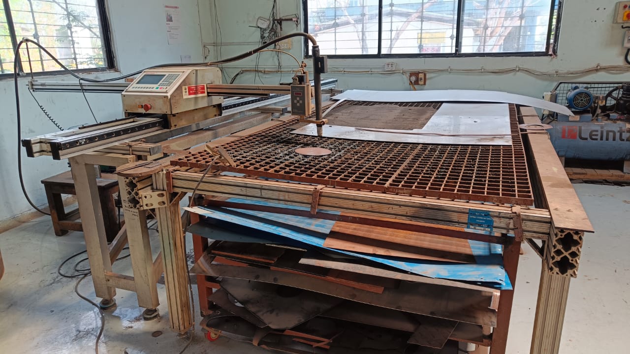
Machine used

Material used
Used MS sheets with 2 mm thickness
Working Steps
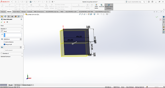
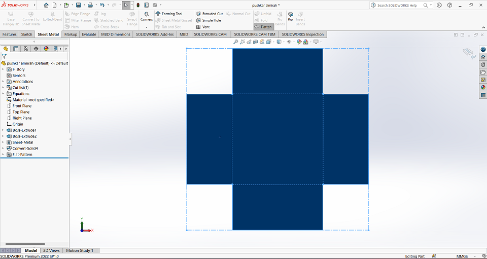
Product Design
I have tried to cut a sheet that can we use for making shelf to store material. So for that I have used Solidworks to design a shelf and then with the use of the sheet metal command I have converted it into a flat region for cutting purposes.
CaM software
I use fastCAM7 software to generate tool path for plasma cutting. After opening it under files section click on DXF restore button to upload file.
.png)
Then selected a file along with DXF file units.
.png)
Opened a DXF file into cam software.
.png)
After uploading dxf file , a pop up screen will open for removing blocks, click on yes.
.png)
Then click on Program path> FastPATH to generate tool path.
.png)
After that click on start FastPATH.
.png)
Then software will generate tool path that can be used for cutting operation.
.png)
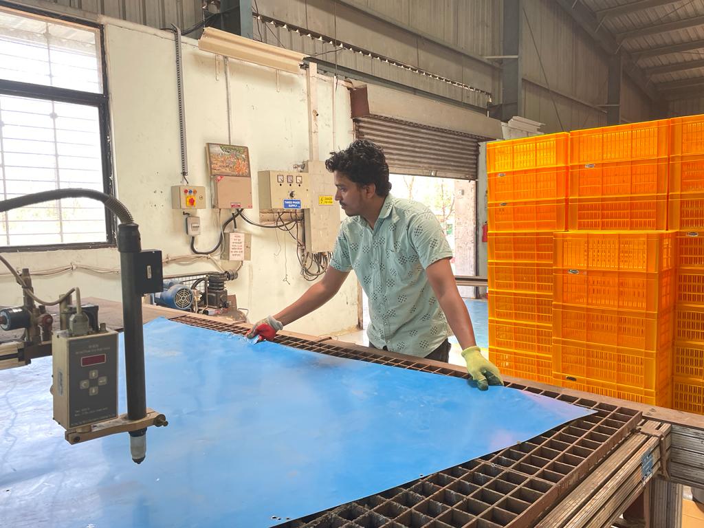
Cutting Process
Initially I have setup metal sheet as per my size and thickness requirement.
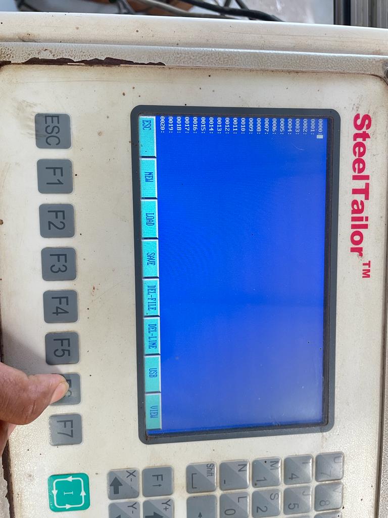
Inserted a USB Drive to the machine, then clicked on edit.
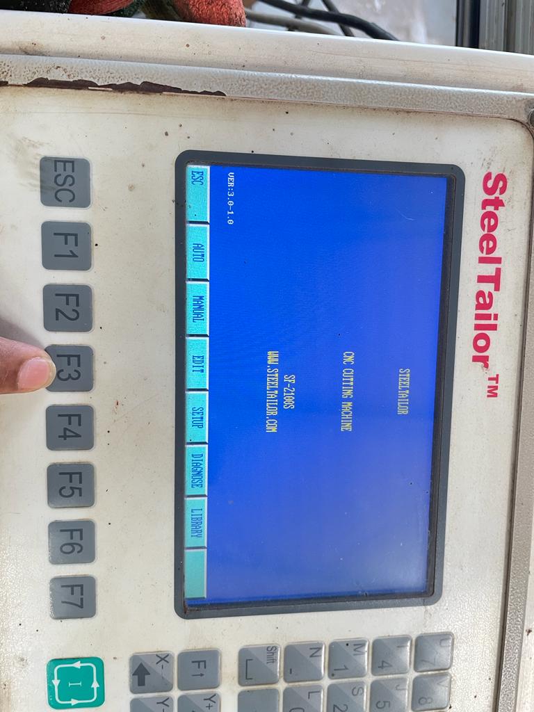
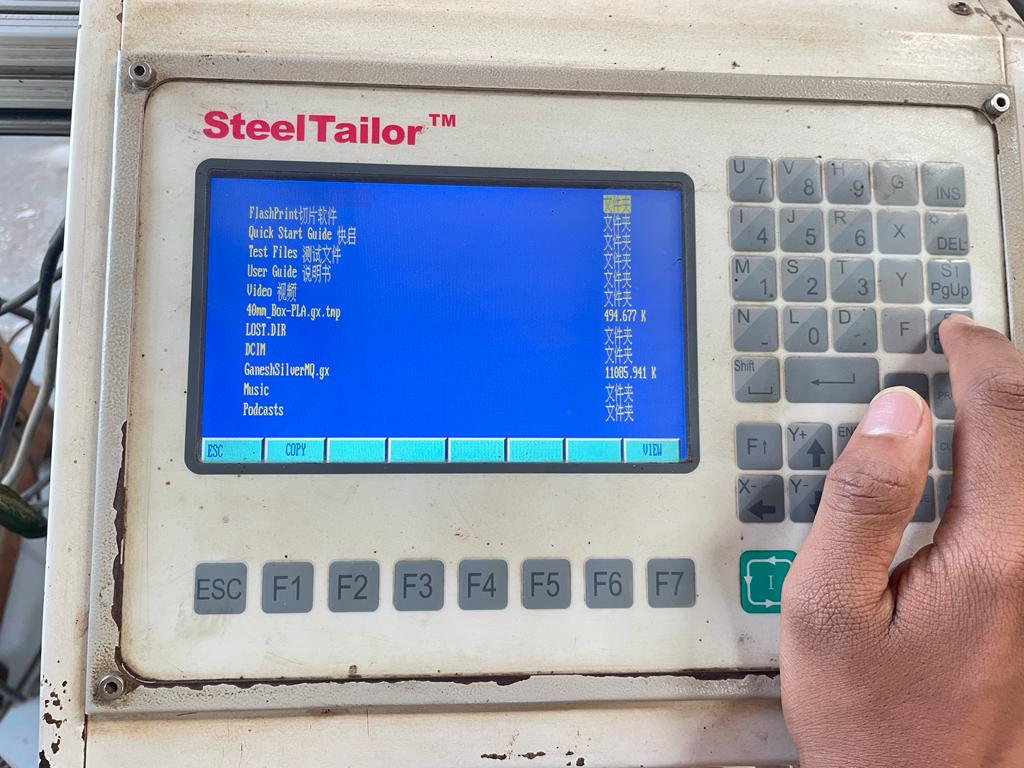
Then I clicked on USB button, to select files form USB.
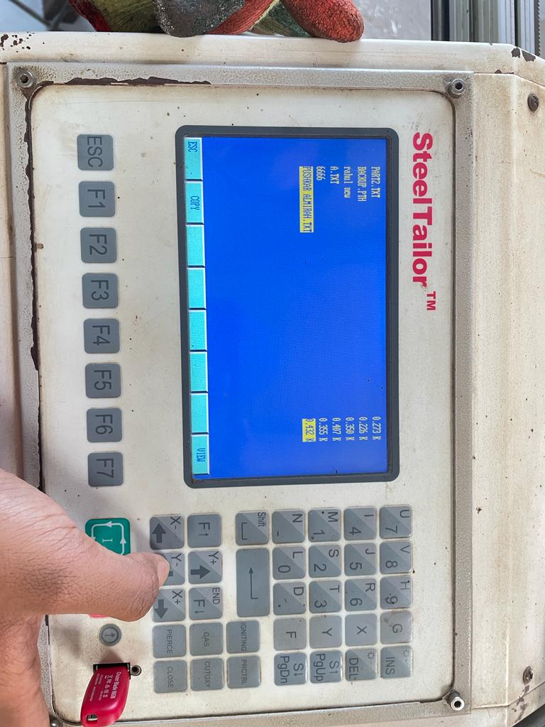
Selected my file from bunch of different files into that drive.
Clicked on the file having tool path which I have generated earlier.
Then by copying it, clicked on view button, machine also provide frame of cutting before actual cutting to reduce failures.
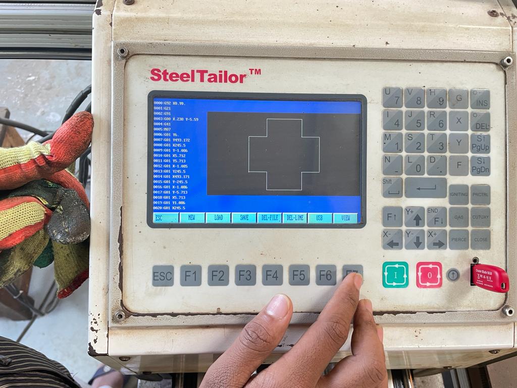
Then by framing it, i started cutting the sheet.
Post Processing
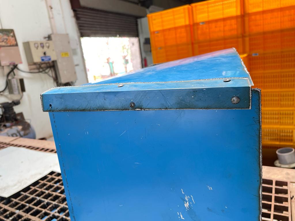
After cutting it, I have bent surface to create a box shape structure from all the ends.
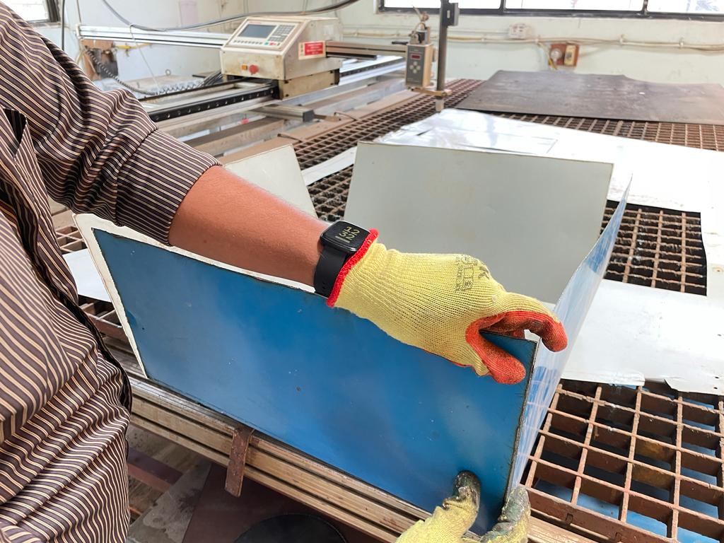
I have also cut the strips from metal sheet to join corner and edges of box as this material having very less thickness and welding starts melting that sheet, so we gone through this option.
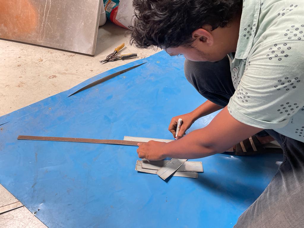
Bent those strips from the center to create L shape structure for joining the edge of box.
Use Revit bolts to punch those clips to the edges.
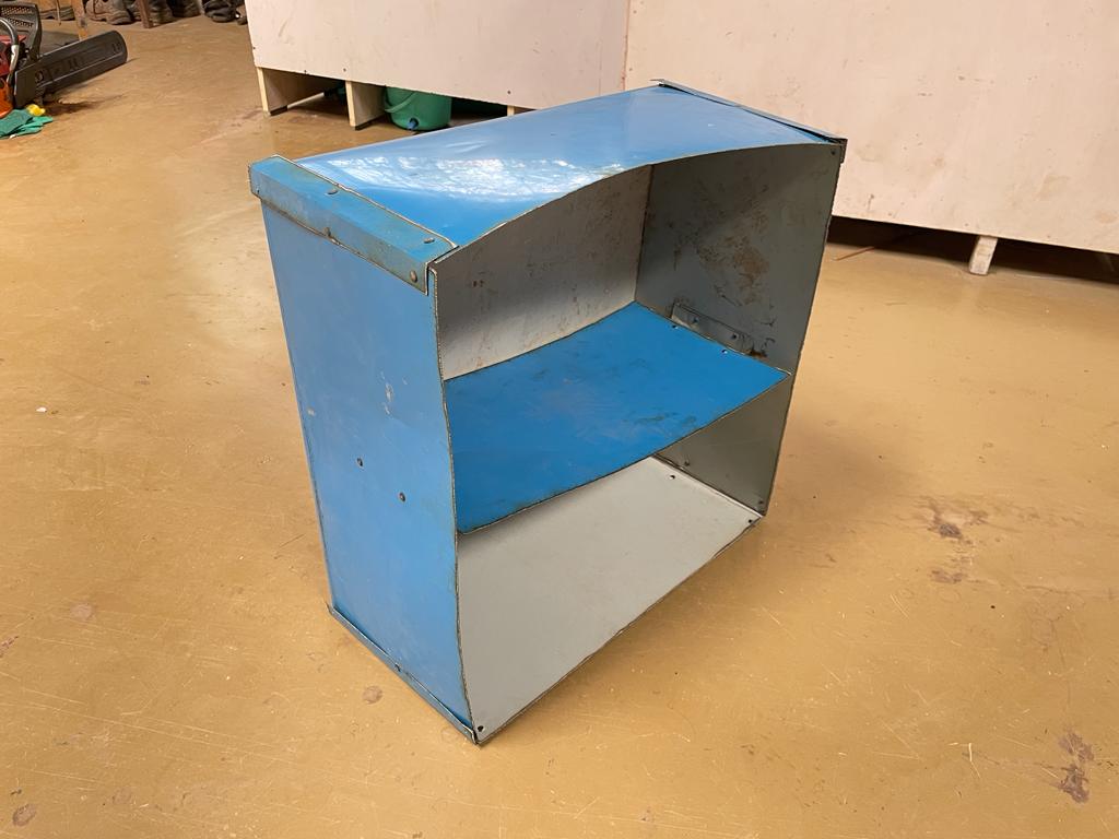
After this fabrication work, the shelf is looking like this, I am aware that the structure is looked that much classy, but as a first trial, I am ok with this, will improve work quality by doing proper hands-on with this.
Video
Learning of the week
Learned how to operate embroidery machine and plasma cutting machine, learn their operations, working , cam software and fabcricated things using these two digital manufcaturing technologies.
What went Well
Plasma cutting gine well, didnt face any major issues.
Able to opearte both machines by self
What went Wrong
Thread gone broken several time during machining.
Faced issue with wlding as sheet is very thin.