Networking & Communication.
Week Assignment summary
For this week, we have designed and manufactured a board considering our final project requirement and communicated using i2c and other wireless protocols.
Here I am documenting all the work that I have gone through for this week.
Objective Of the Week
Individual Assignment – For the individual assignment we have to design and manufacture a microcontroller board, then using i2c protocol we have to transfer the data collected to thingspeak using the Wi-Fi interface.
Group Assignment – For the group assignment, we communicated between two ESP32 c3 boards and transfer data like temperature and humidity collected by one board and collected at second board.
Learnings of the week
Types of Data Signals
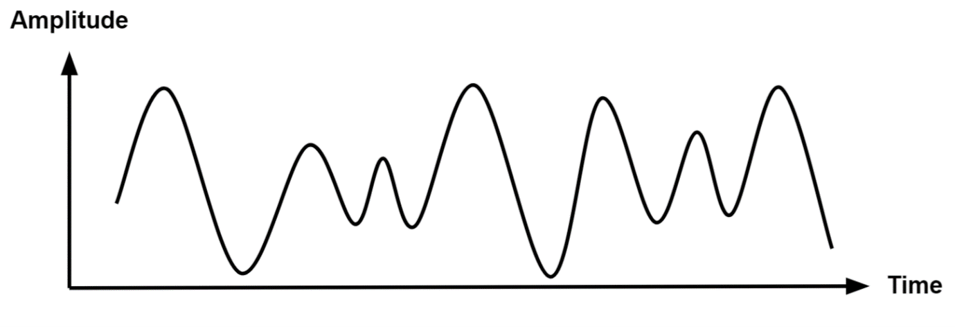
Anolog Signal
Analog signals are waves that keep going up and down without stopping. They can change in strength and speed, just like the waves in the sea.
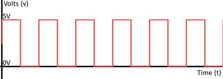
Digital Signal
- Digital signals are signals that have a limited number of values. They can only be 'on' or 'off' and are represented by a code made up of only 0s and 1s.
OSI Layers
OSI (Open Systems Interconnection) layers are a way of organizing communication between computer systems. There are seven OSI layers, each with its own unique function. The layers are designed to work together to ensure that data is transmitted reliably and efficiently between devices. The layers are named as follows:
• Physical Layer
• Data Link Layer
• Network Layer
• Transport Layer
• Session Layer
• Presentation Layer
• Application Layer
Each layer has a specific role in the communication process, and they build upon each other to create a complete communication system.
Communication Protocol.
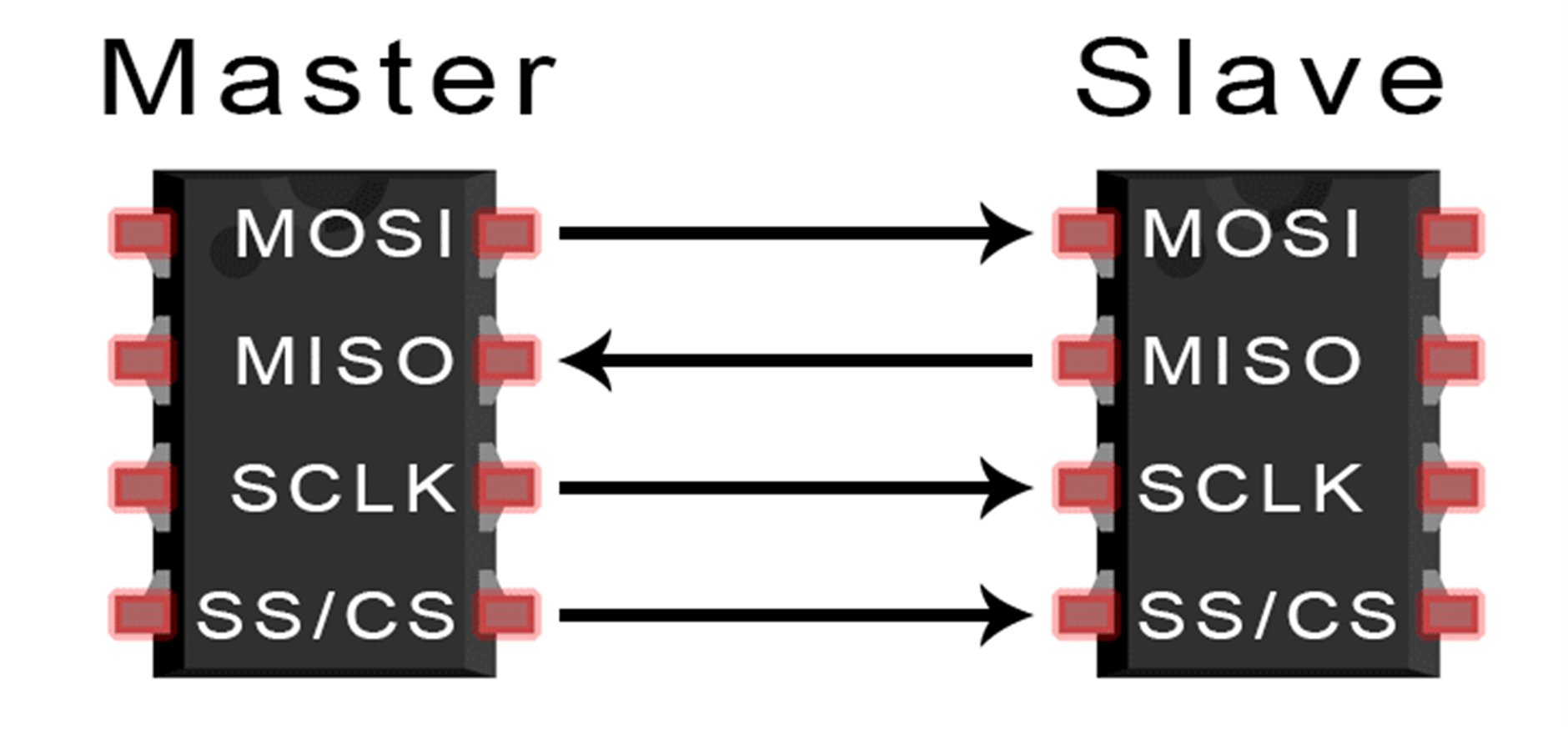
SPI
SPI (Serial Peripheral Interface) protocol is a communication protocol used for transmitting data between microcontrollers and peripheral devices. It is a synchronous protocol, which means that data is transmitted in sync with a clock signal.
SPI uses a master-slave architecture, where one device (the master) controls the communication, and one or more devices (the slaves) respond to the master's requests. The communication is done through four wires:
MISO (Master In, Slave Out)
MOSI (Master Out, Slave In)
SCLK (Serial Clock)
SS (Slave Select)
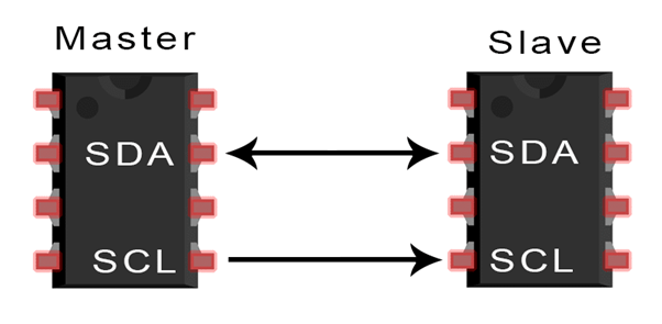
I2c
I2C (Inter-Integrated Circuit) protocol is a communication protocol used for transmitting data between microcontrollers and peripheral devices. It is a synchronous protocol, which means that data is transmitted in sync with a clock signal.
I2C uses a master-slave architecture, where one device (the master) controls the communication, and one or more devices (the slaves) respond to the master's requests. The communication is done through two wires:
SDA (Serial Data)
SCL (Serial Clock)
Wi-Fi
WiFi (Wireless Fidelity) protocol is a set of standards for wireless local area networks (WLANs). WiFi allows devices to connect to a network and communicate wirelessly with other devices on the same network.
WiFi uses radio waves to transmit data between devices. The data is transmitted using a protocol called IEEE 802.11, which specifies the rules for wireless communication.
WiFi allows for high-speed data transmission and enables devices to connect to the internet without the need for physical cables. WiFi networks can be set up in homes, businesses, public spaces, and other areas to provide wireless access to the internet and other network resources.
Bluetooth
Bluetooth protocol is a wireless communication protocol used for short-range data transmission between devices. Bluetooth allows devices to connect and communicate wirelessly with each other without the need for cables.
Bluetooth uses radio waves to transmit data between devices. The data is transmitted using a protocol called Bluetooth Core Specification, which specifies the rules for wireless communication.
Bluetooth technology is commonly used in smartphones, tablets, laptops, wireless headphones, and other devices to connect and share data with each other.
Lora
LoRa (Long Range) protocol is a wireless communication protocol designed for the long-range transmission of low-power signals. It is a proprietary technology developed by Semtech Corporation.
LoRa uses radio waves to transmit data over long distances, up to several kilometers, while consuming very little power.It is commonly used in Internet of Things (IoT) devices, smart cities, agriculture, and industrial automation applications.
Individual Assignment
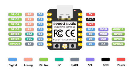
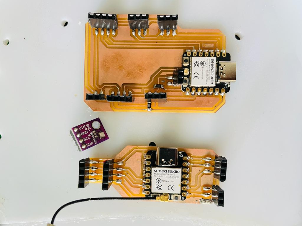
For this assignment, I have used the Xiao ESP32 C3 board, as this module has built-in Wifi and Bluetooth Communication protocol.
Pin Out the structure of the Xiao ESP32 C3 module.
Board Design and Production
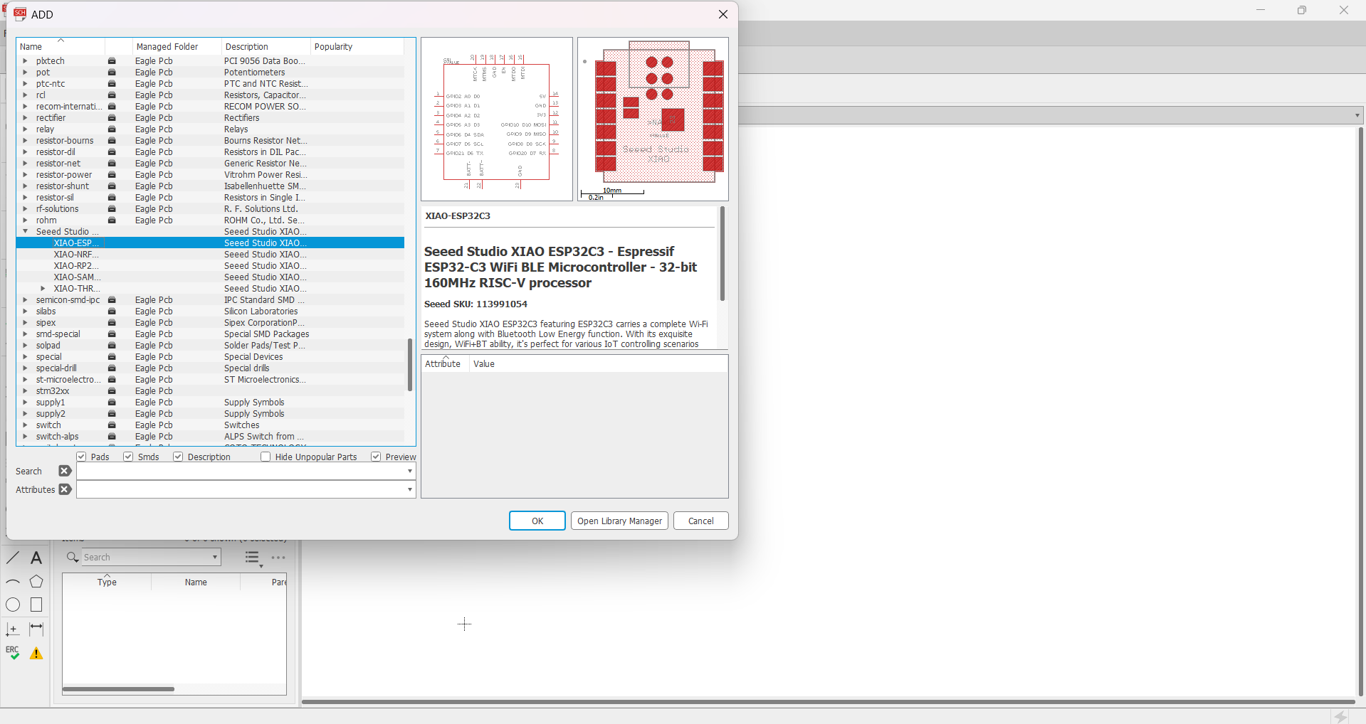
Downloaded a library for XIAO ESP32 board for the eagle.
Basic Skematic structure of micro-controllor board.
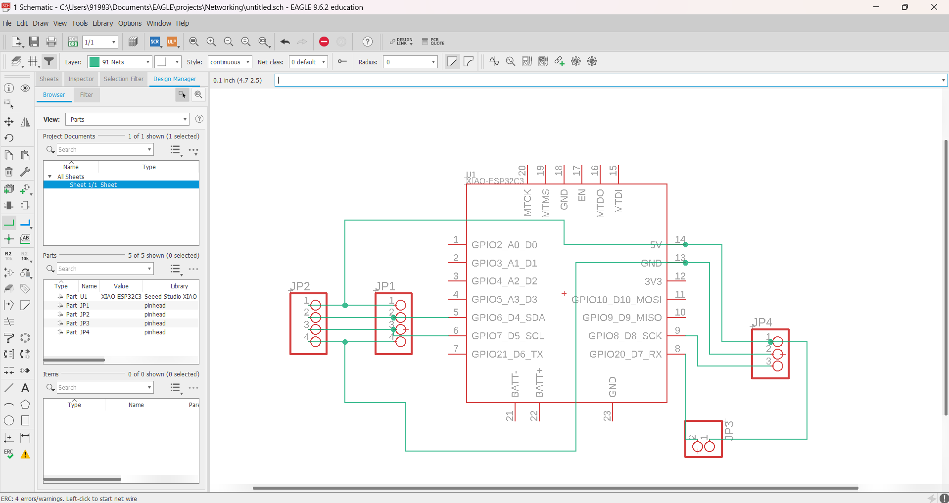
After doing ERC check I have switched tho the board design.
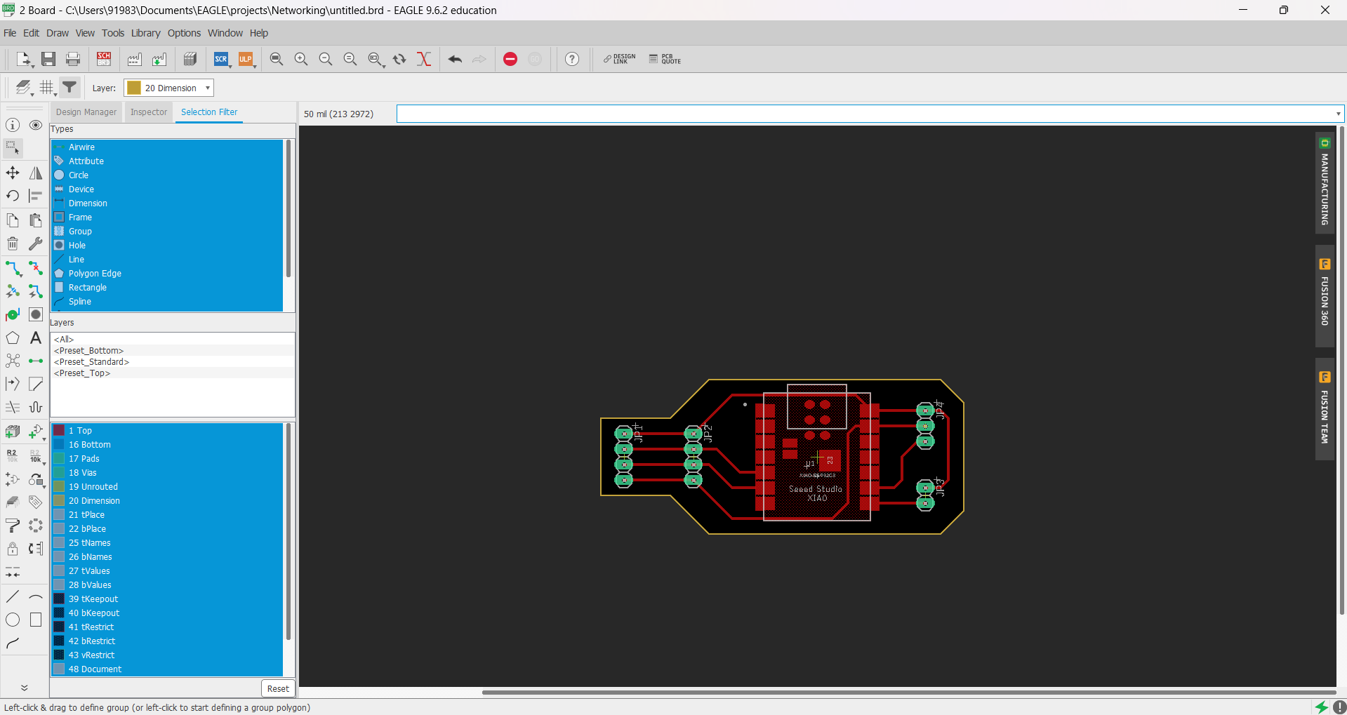
By routing each collection and by doing DRC check I have downloaded PNG for the both Traces and interior.
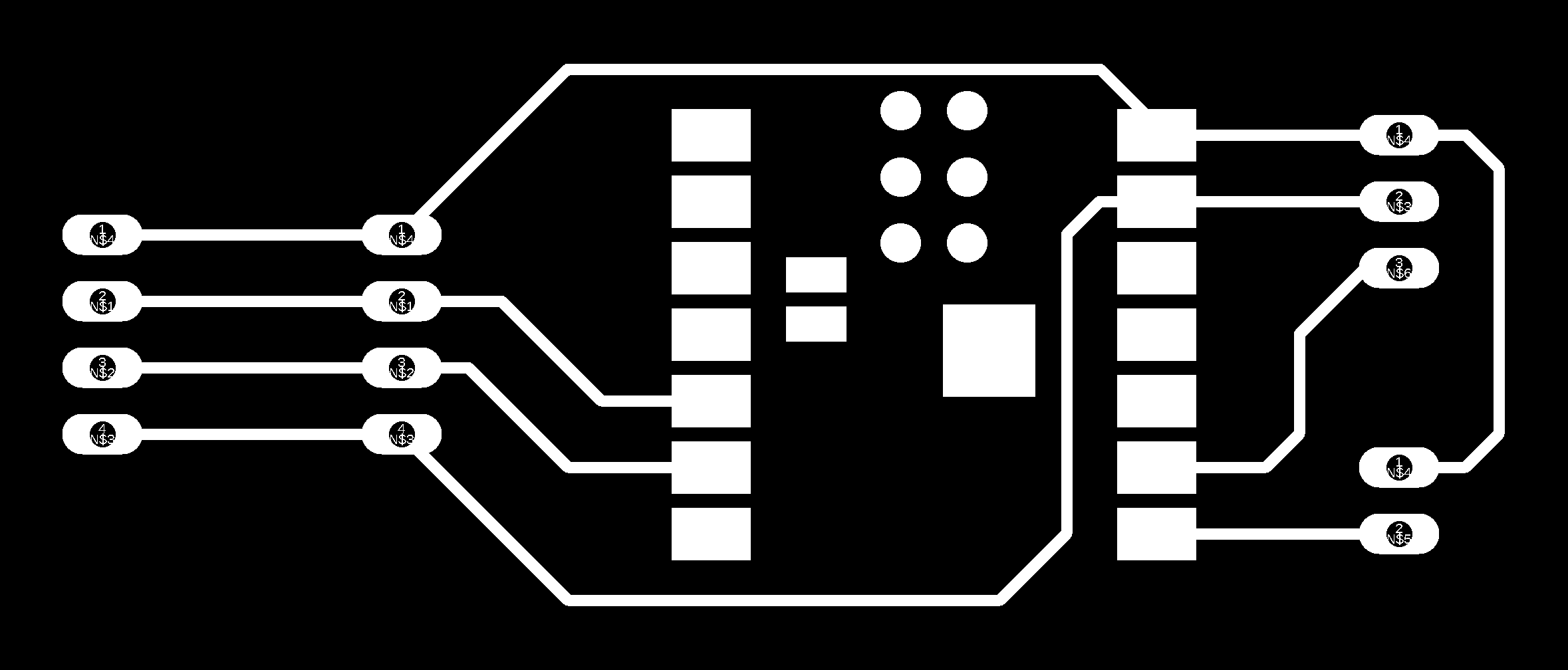

Component Used
XIAO ESP32 C3 –
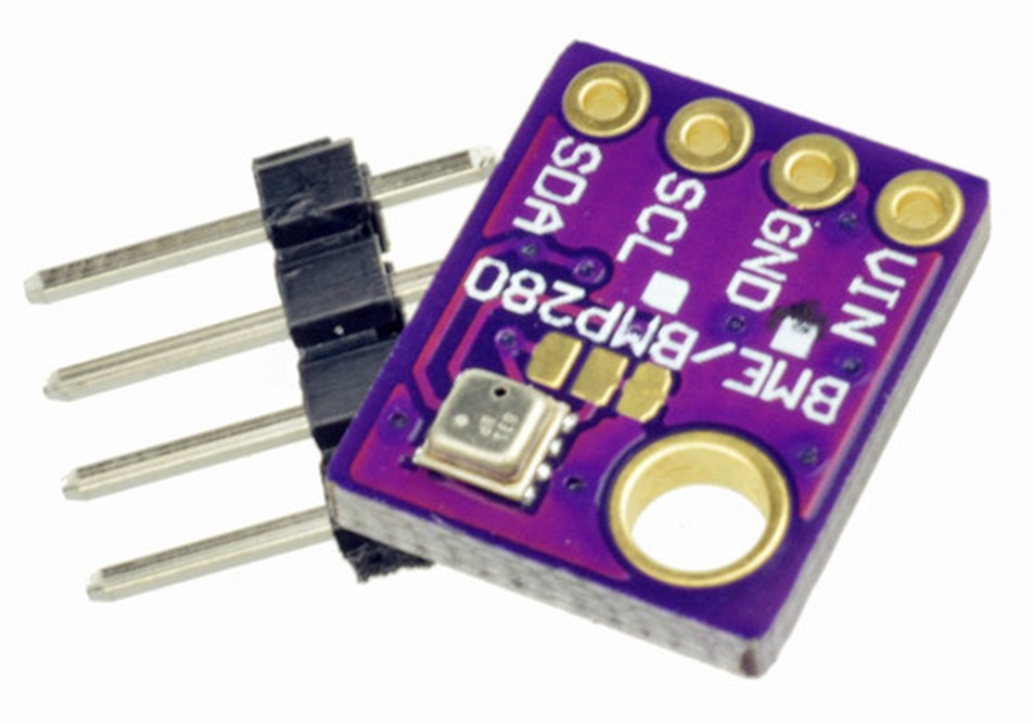
BME280 –
Communication Protocol Used to trasfer data to thingspeak
To trasfer data collected by BME sensor to thingspeak cloud using Xiao esp32c3 microcontrollor board, i used i2c and internet protocols.
I2C (Inter-Integrated Circuit):
I2C is a communication protocol commonly used to connect multiple devices on a single bus. It allows for bidirectional communication between a master device (in this case, the Xiao ESP32C3) and one or more slave devices (such as the BME sensor). The ESP32C3 communicates with the BME sensor using I2C to retrieve sensor data.
Internet Protocol
The Internet Protocol (IP) is the fundamental protocol used for communication over the internet. It provides a way to send packets of data across networks. In your case, the Xiao ESP32C3 uses the IP protocol to establish an internet connection and communicate with ThingSpeak.
Libraries
To program the Xiao esp32 c3 module using Arduino Ide we need to install all the required libraries of Xiao ESP32 c3 board to Arduino ide.
To use and program BME280 HTP sensor, I downloaded the libraries for that and installed it to Arduino ide.
As individual assignment, I have given myself a task to calculate Temp and humidity and show it to the thingspeak portal in the form of chart.
Program
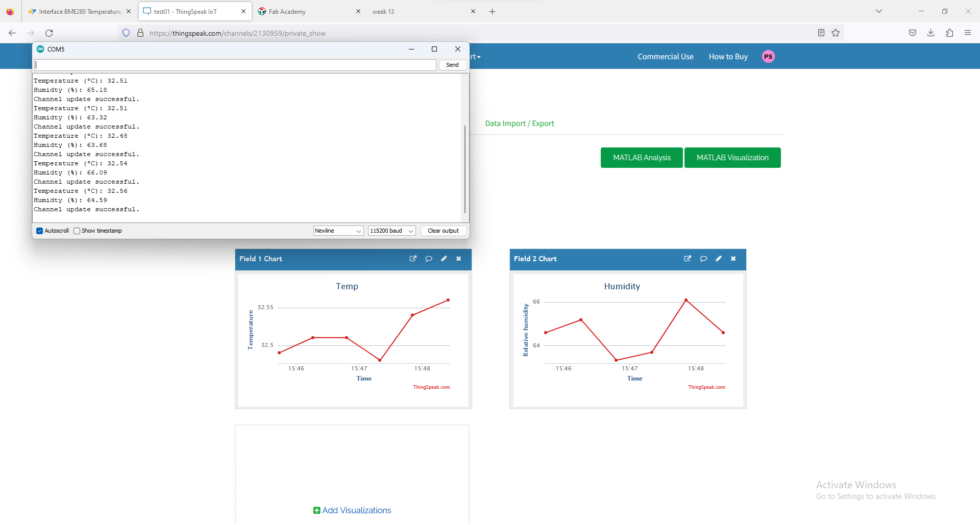
Initially I have created a account on thingspeak and I only have to read the data sended by the controller so I have pick up the API keys for Read only.
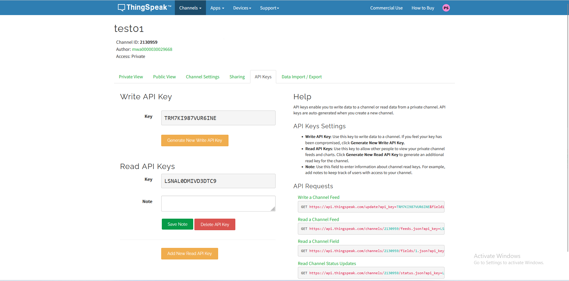
Inserted that API key and Local wifi details and programmed it.
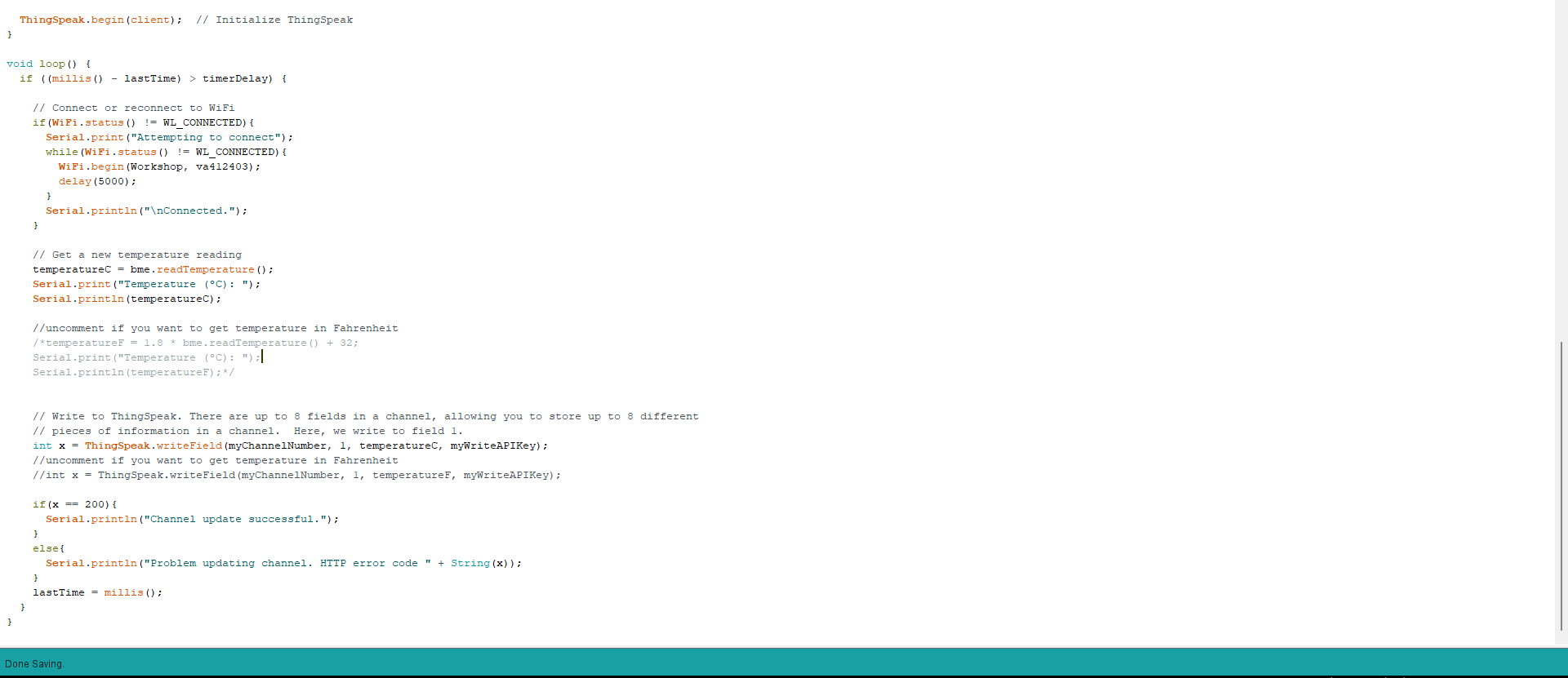
After completing and uploading the program I opened Thingspeak and under channels > private view. I can clearly see that it really works and the I am able to see all the calculated values into this.
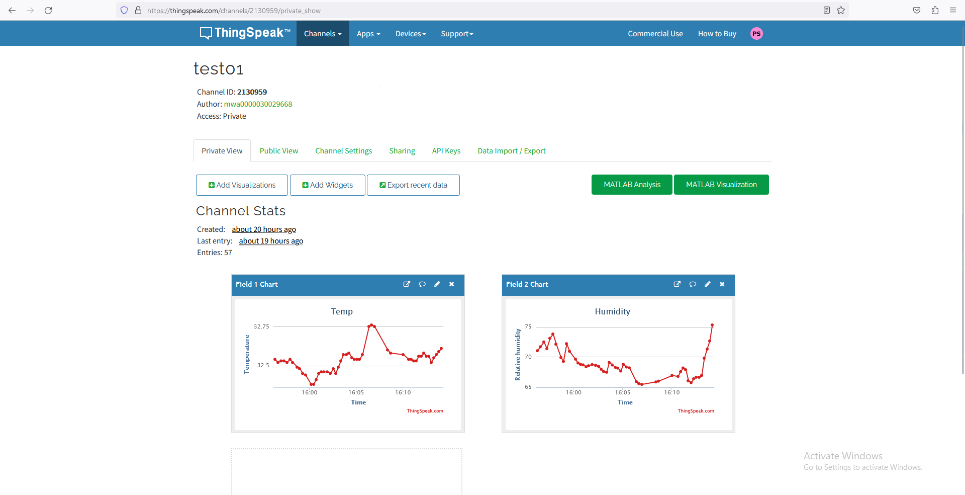
By comparing point of view I have seen the calculated values under serial monitor and compared it. And the values shown by the thingspeak and the series monitor is same.
Group Assignment
Interaction between two Xiao ESP32 c3 boards.
For this group assignment, we have decided to measure temperature and humidity with one microcontroller board and plan to display it through a second micro-controller board.
We have used two XIAO ESP32 c3 boards to communicate with each other, both boards were designed by considering final project requirements.
Program
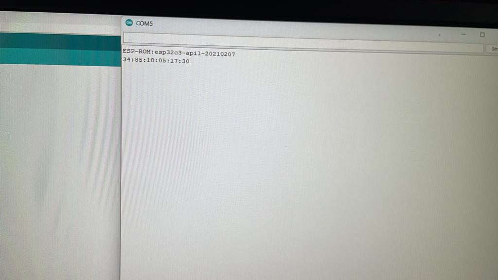
For the interaction between two boards, initially we have extracted Mac id of both the controllers using below code.
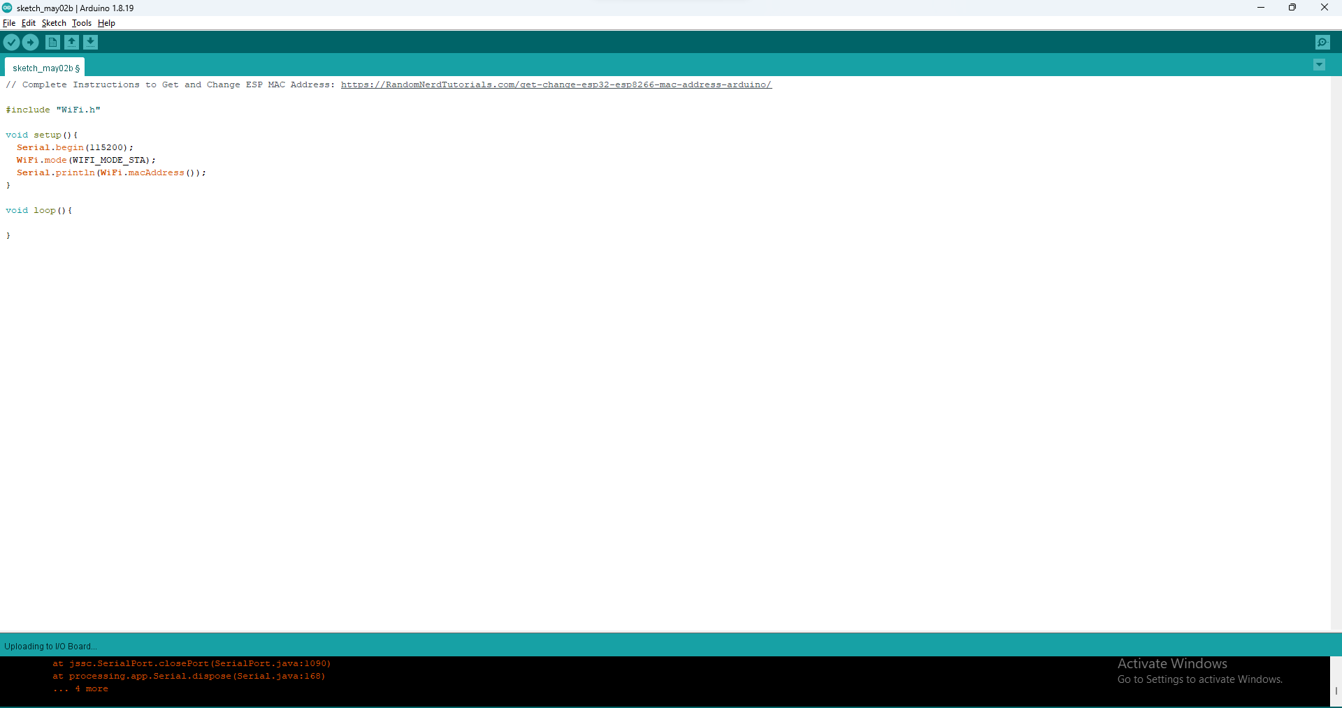
This is generated Mac id for the first board.
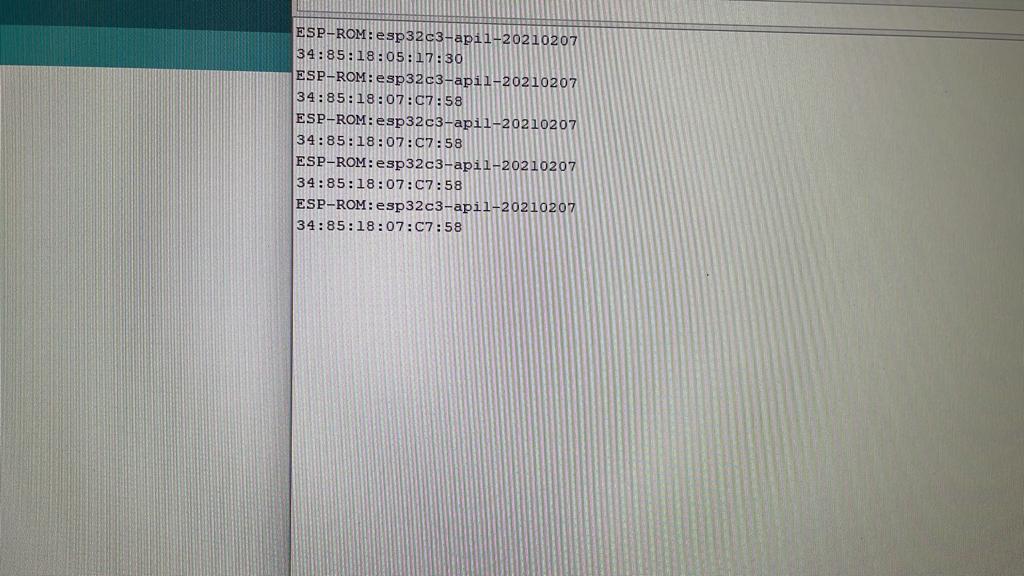
This is Generated Mac id for second board.
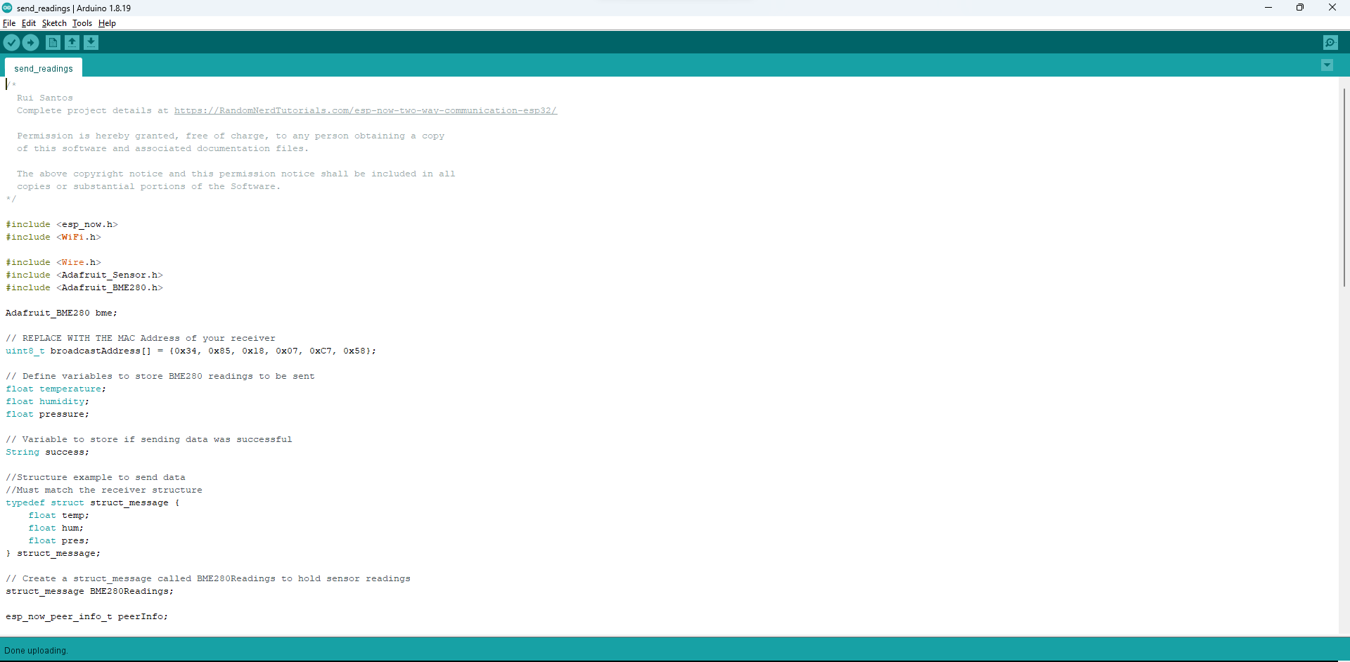
Program for sending data from the first controller, where we put the generated mac id for receiver controller.
This a program for receiving data at a second micro-controller, here we have put the max id generated by the sender micro-controller board.
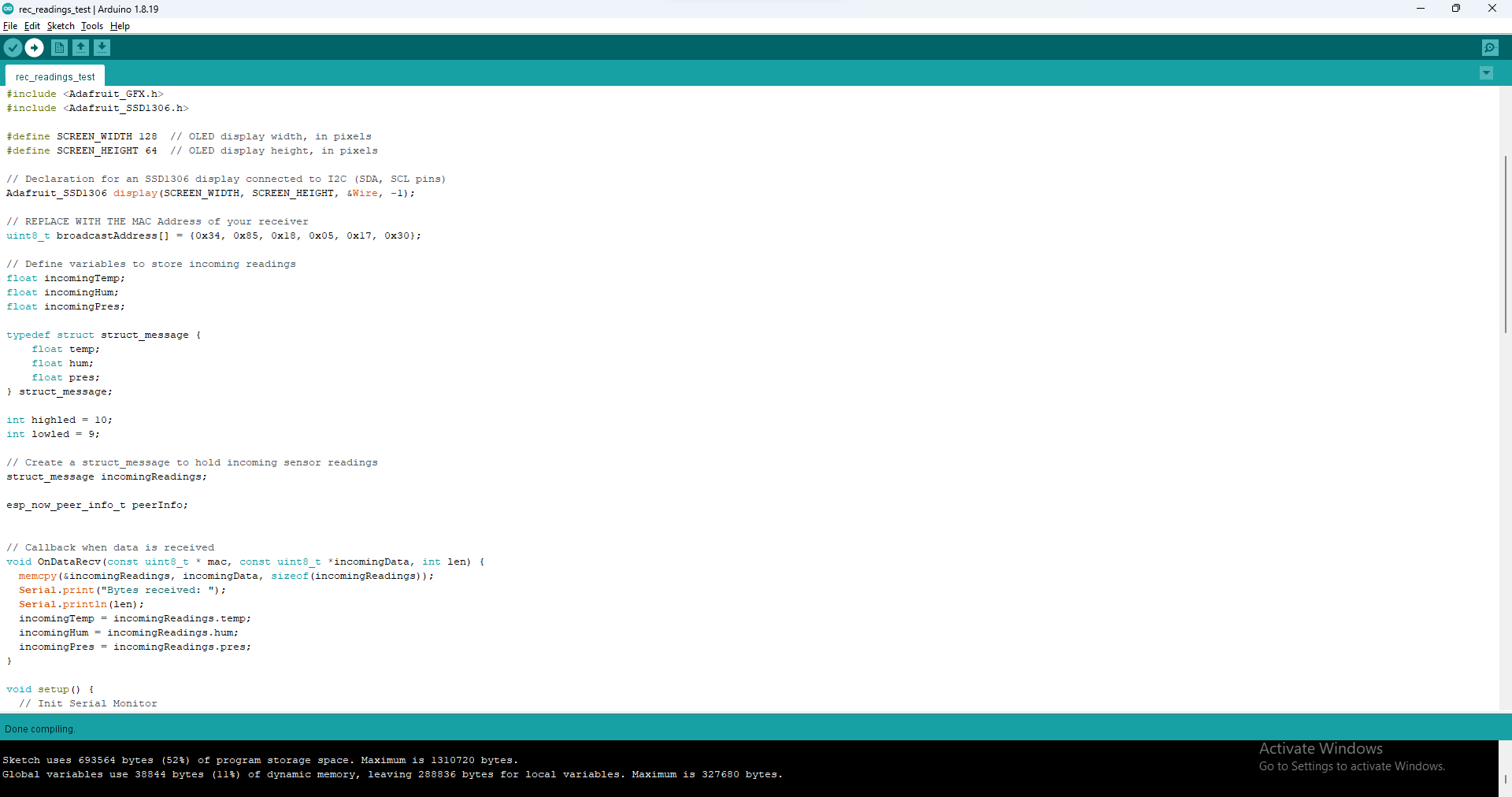
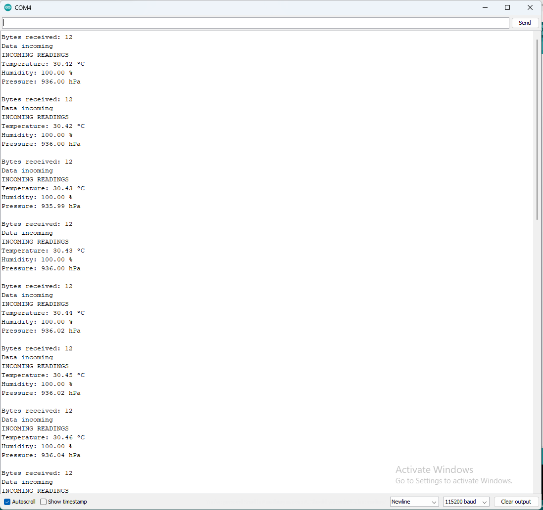
Initially, we have planned that to measure the readings from first board and to display the measured reading at the second board with OLED display. But unfortunately OLED didn’t work well so received the reading to serial monitor of receiver controller.
What went well
1) Able to transfer data using wireless connection.
2) able to communicate between two boards.
Went went worng
1) faced issue with programming, as it showing errors for missing library with Arduino IDE. so i have installed previous or old vergion of Ardiono and that error got removed.