Input Devices
Week Assignement summary
For this week 12, we worked with different input devices, and with their programming, we also did the Design and manufacturing of PCB with ATtiny 1614 microcontroller..
Here i have documented all of my works with different softwares like eagle, Mods, VPanel and production of my Third PCB.
Objective Of the Week
For the Group assignment, we studies signals passed by different input devices using an oscilloscope in our FAB lab Vigyan Ashram.
For the individual Assignment, I studied and used different input devices with the microcontroller board that I have designed.
What are input Devices
In computing, an input device is a piece of equipment used to provide data and control signals to an information processing system, such as a computer or information appliance. Examples of input devices include keyboards, mouse, scanners, cameras, joysticks, and microphones.
Board Manufcaturing.
For this i have designed another board for to test and run different input devices, so i have designed a board with ATtiny 1614 Controller provided with I2c Connection
Board Design
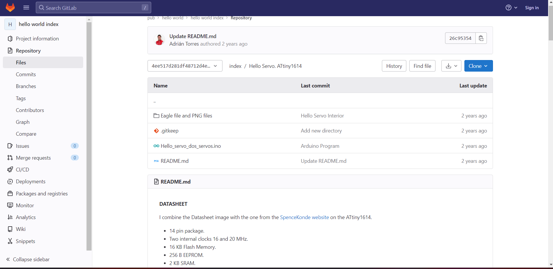
Downloaded and imported library for Attiny 1614 microcontroller.
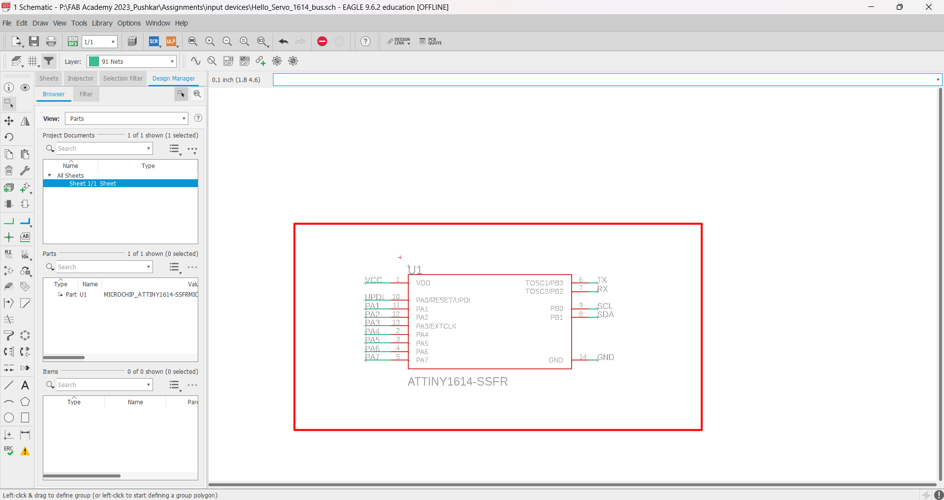
Added schematic of Attiny 1614 microcontroller.
Added 1*3 Pinhead with pads.
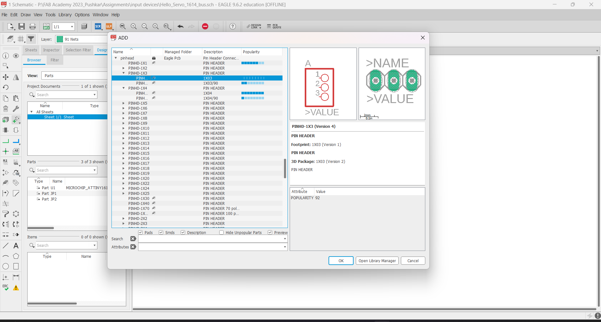
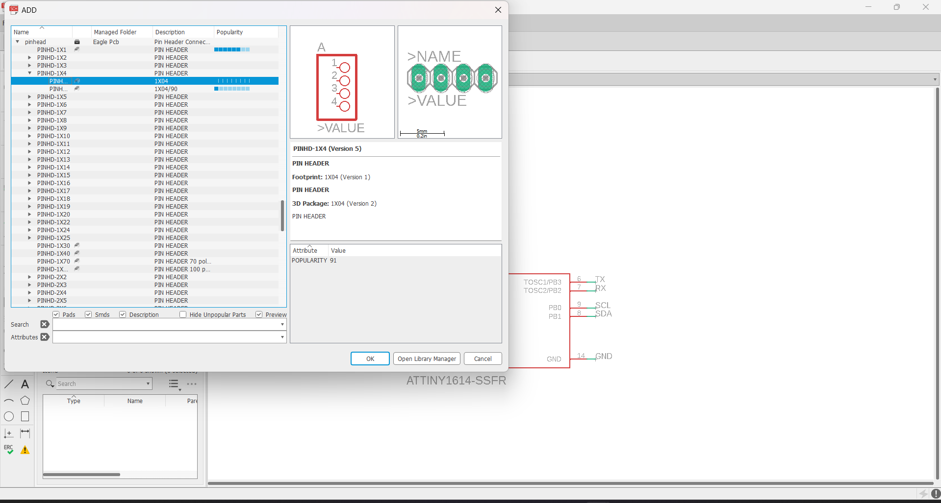
Added 1*4 Pinhead with pads.
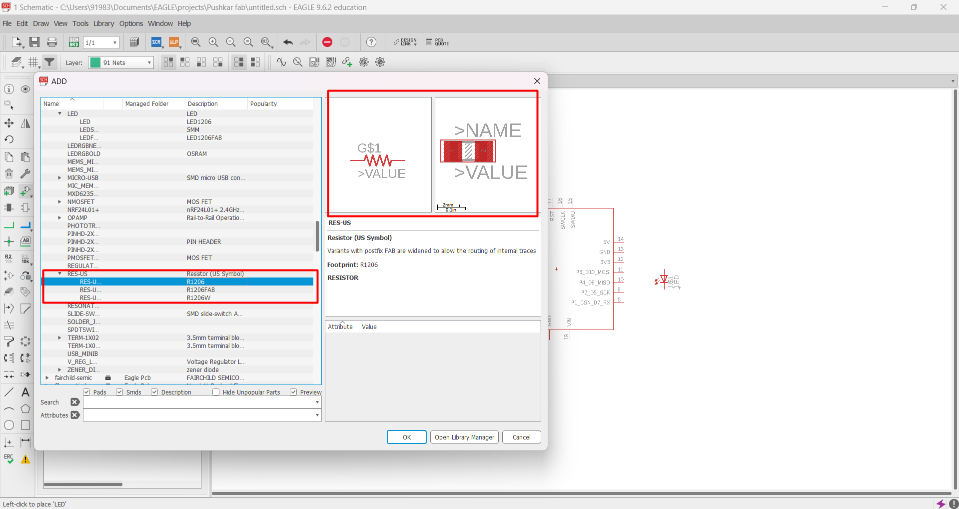
Added SMD LED to schematic board design..
Added 2 resistors. One 100 ohm resistor for Led & one 1 ohm resistor used for trace jumping.
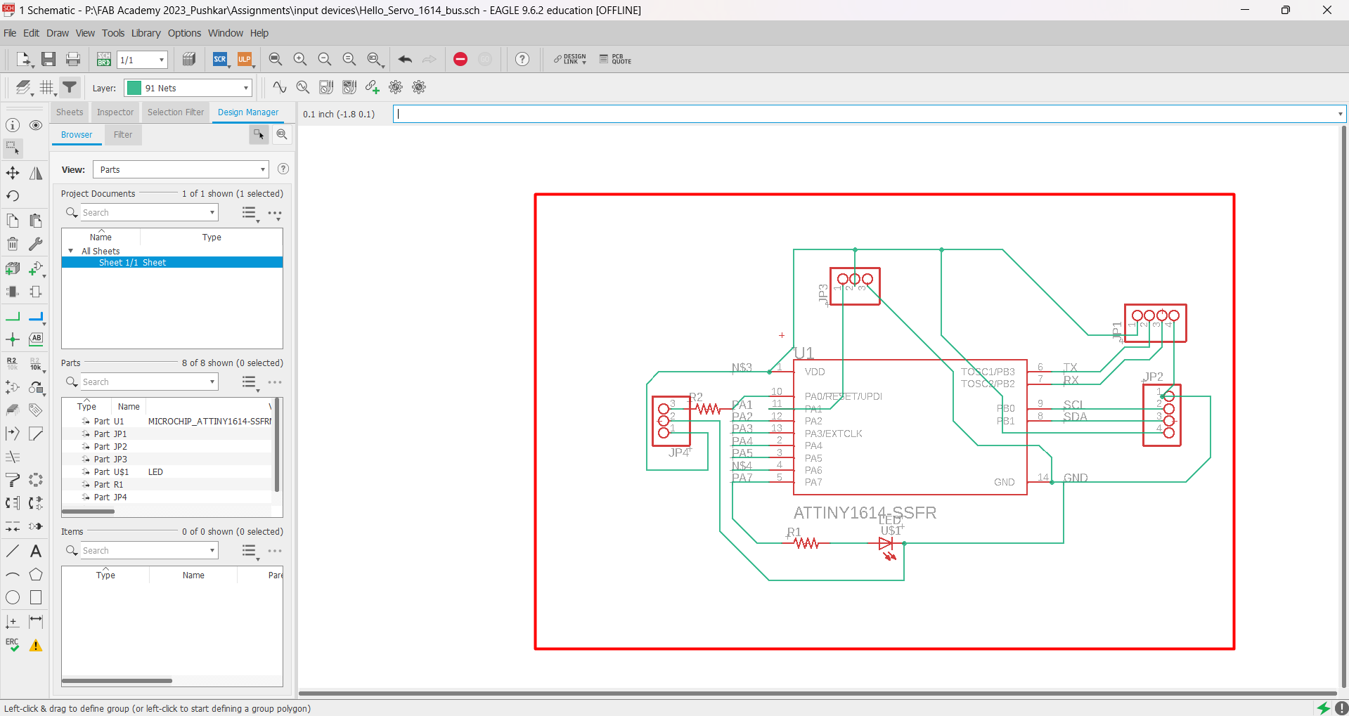
After connecting all the components I have completed my sketch work and the final schematic design is look like this.
After completing ERC check, I have generated board designed and started routing it.
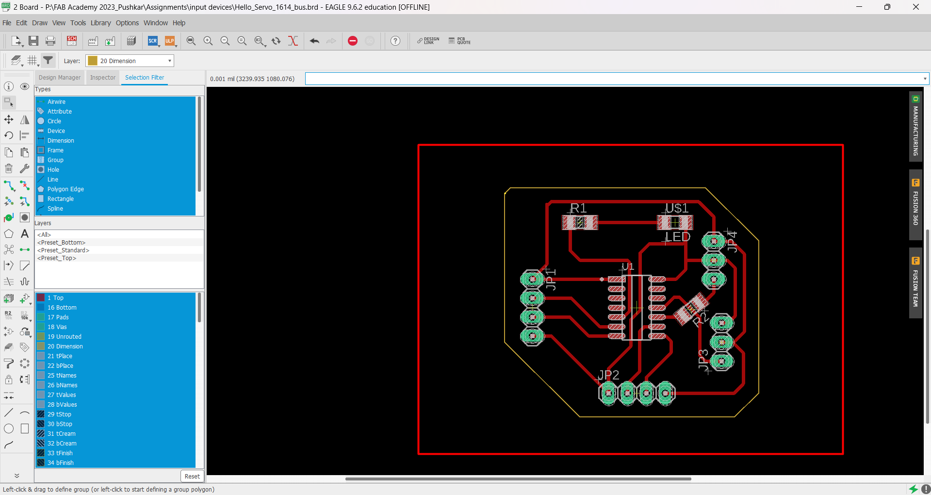
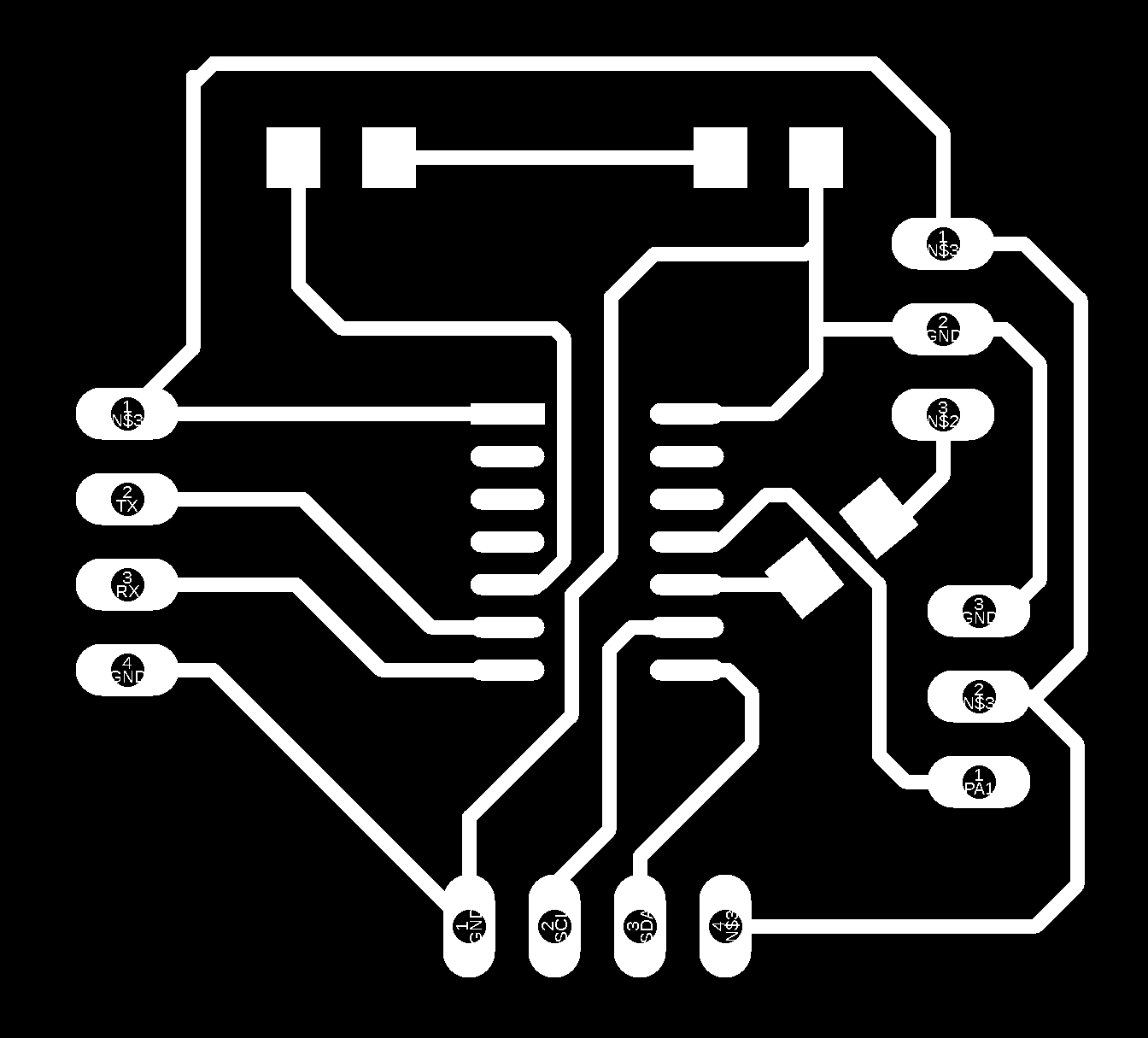
After completing DRC check, I have downloaded .png files of both the traces and the border of PCB board.

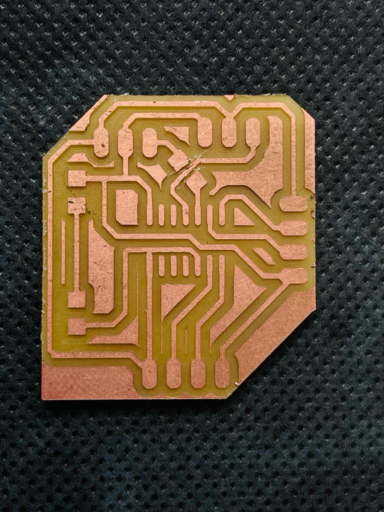
Board Milling
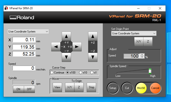
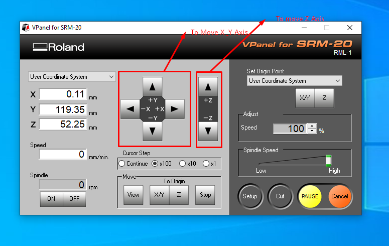
Then after using Fab academy community mods I have generated tool path for PCB milling, and the file frmat generated is .rml file.
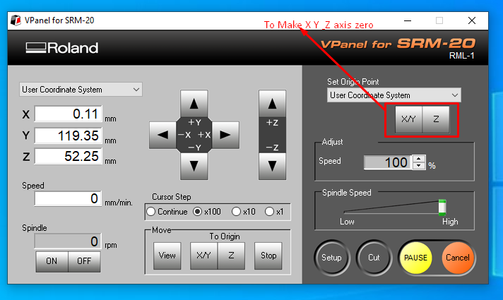
After milling of both traces and interior final milled board is looking like this.
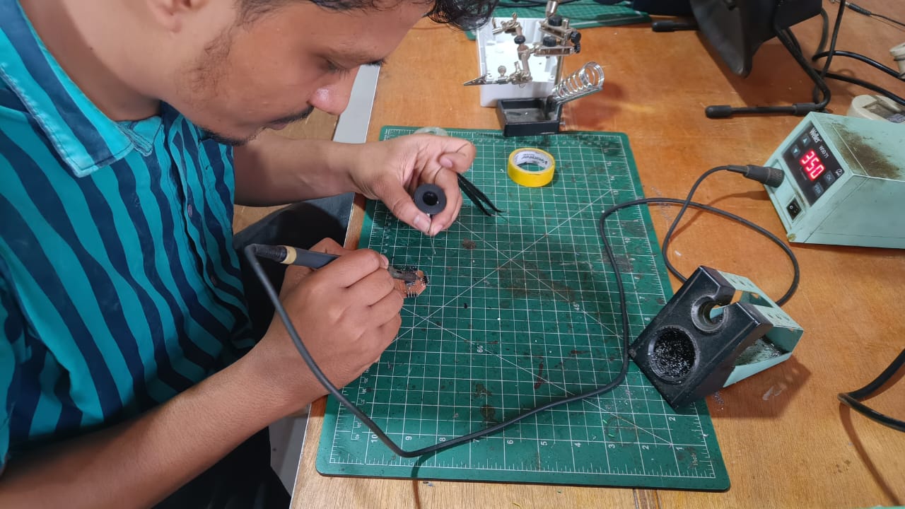
Soldering
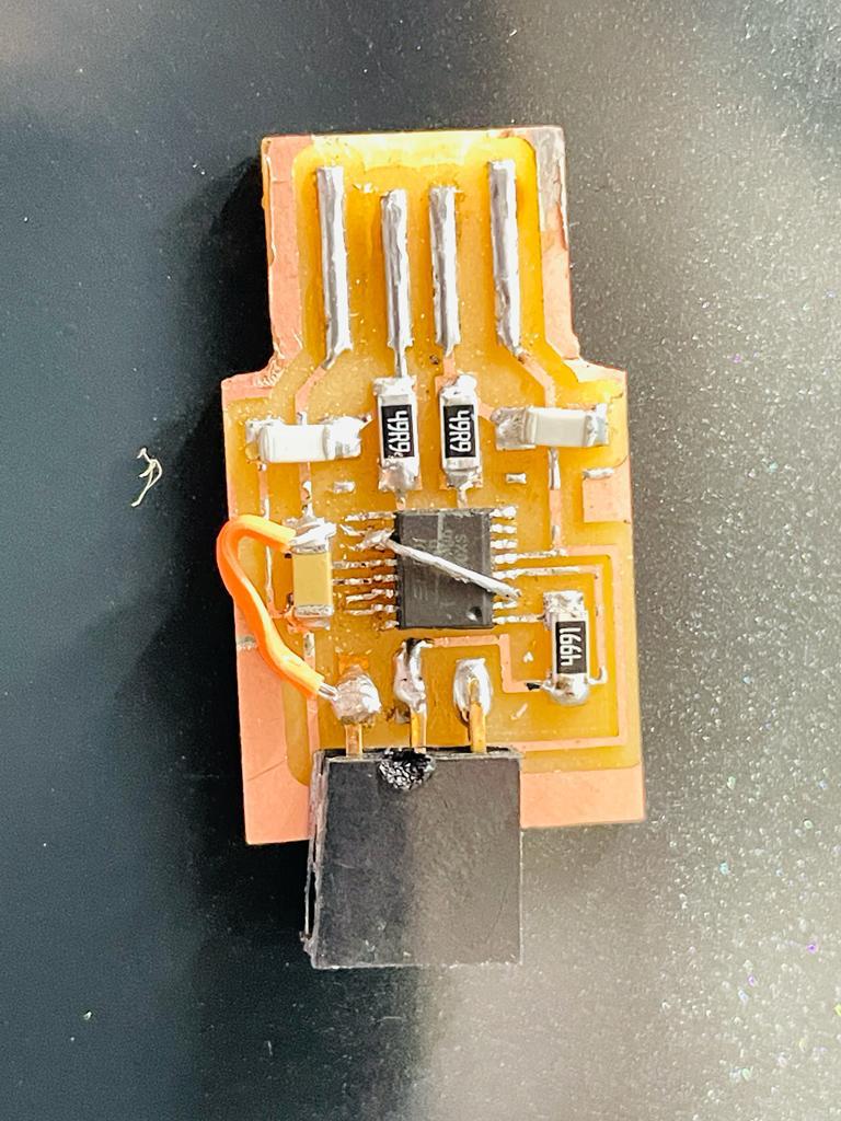
After completing the milling process, I soldered the components to the PCB board like LED, Pinheads, Resistor, and Attiny 1614 microcontroller.
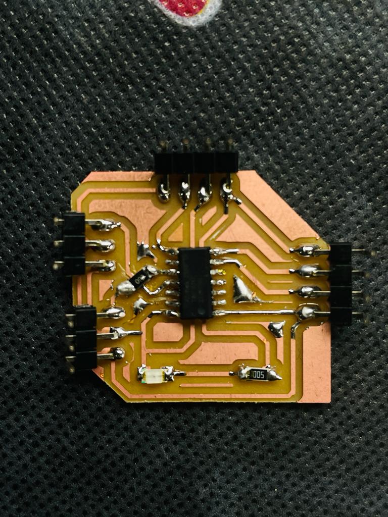
Final Board
After completing the soldering process, my final board looks like this.
Programmer Board
As we have used Atitiny 1614 board, we need to design a programmer board to interface it with Arduino ide and for program uploading.
Programming & Testing
Attiny 1614 Library for Arduino ide.
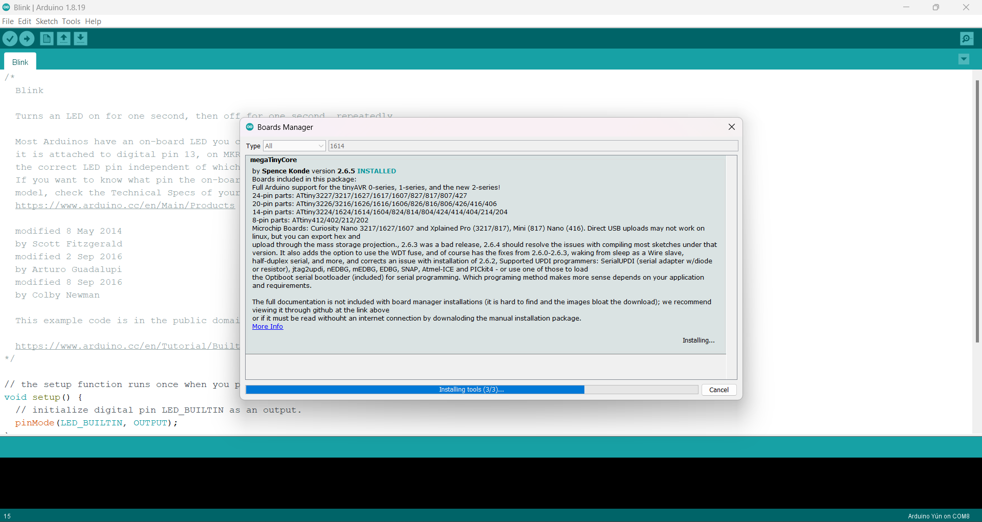
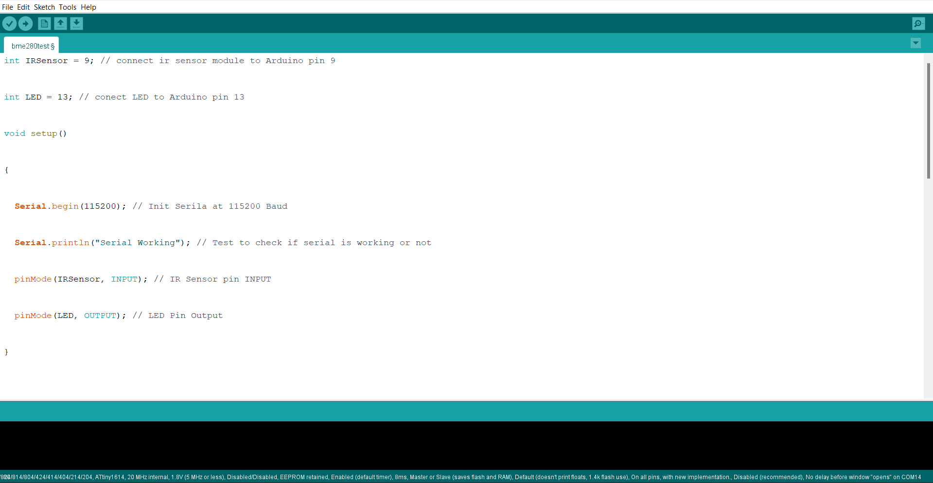
Programming & testing for Led blinking.
Programing For LED Blinking.
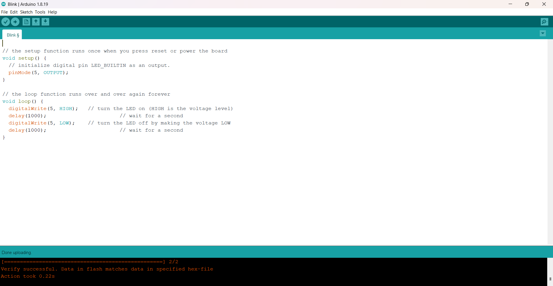
LED Blinking
Programming & testing for Ultrasonic Sensor
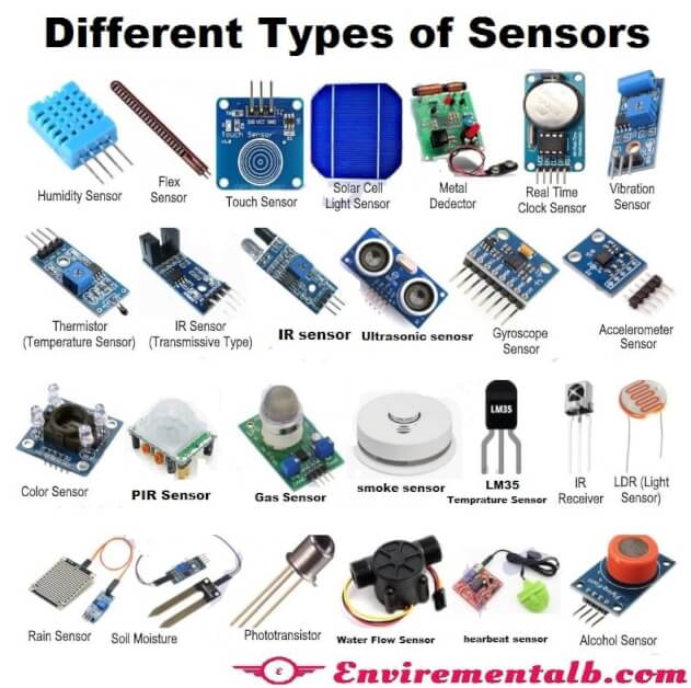
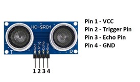
An ultrasonic sensor is an instrument that measures the distance to an object using ultrasonic sound waves. An ultrasonic sensor uses a transducer to send and receive ultrasonic pulses that relay back information about an object's proximity.
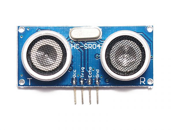
Pin out- Ultrasonic sensor
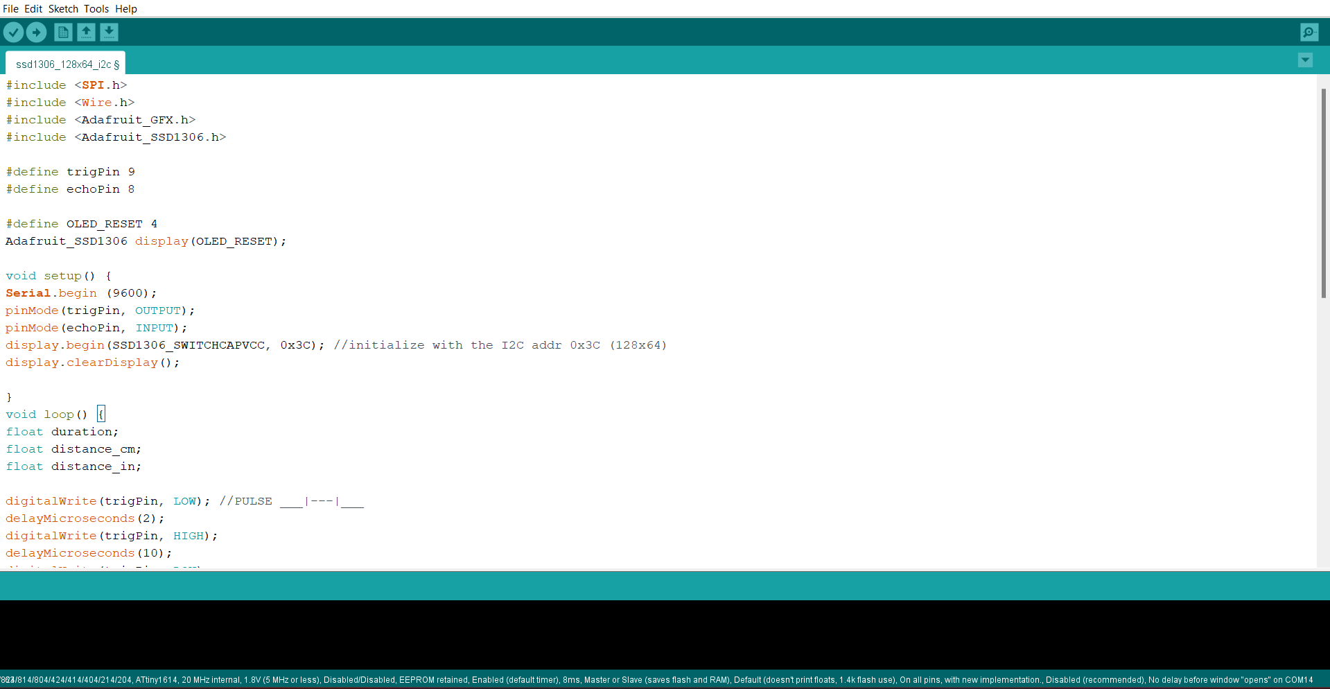
Program For Ultrasonic Sensor
Programming & Testing for LDR sensor.
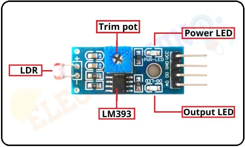
LDRs are tiny light-sensing devices also known as photoresistors. An LDR is a resistor whose resistance changes as the amount of light falling on it changes. The resistance of the LDR decreases with an increase in light intensity. This property allows us to use them for making light sensing circuits..
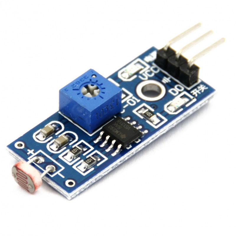
Pin out- LDR Sensor
Program For LDR Sensor.
LDR Sensor
Learning from this week
1) Can able to use Different input devices and their programming with arduino ide.
2) able to do soldering of SMD Components
3) Become more familier with electronics
Problem Faced
A) Traces got damaged during the soldering process, which caused I2C connection not to work.
B) Faced Issue with desoldering of misplaced components.