Machine Building
Jalebi Maker By Fab Lab Vigyan Ashram
For this machine building week, we did manufacture and tested Jalebi Making machine. We did all the required fabrication along with electronics work to ensure design outcome of this jalebi making machine.
About Jalebi Dish
Jalebi (Hindi: जलेबी), is a popular sweet snack in south and west Asia, Africa, and Mauritius. It goes by many names, including jilapi, zelepi, jilebi, jilipi, zulbia, jerry, mushabak, z’labia, or zalabia.
The south Asian variety is made by deep-frying maida flour (plain or all-purpose flour) batter in pretzel or circular shapes, which are soaked in sugar syrup. Jalebi is eaten with curd or rabri (in North India) along with optional other flavors such as kewra (scented water).

Traditional Mathod For Jalebi
Traditionally jalebi making sone by depositing raw mixture of jalebi through small circular hole of a cloth and the design and shape of jalebi to be produced depends on the operator’s skills.

Motivation To Automate Jalebi Making Process
We decided to automate the Jalebi manufacturing process by considering three major reasons.
1) Skilled operator plays a major role to cook the best jalebi as the thickness of jalebi, applied pressure while deposition and the motion of hand should be proper and accurate.
2) Due to its manual work, making jalebi in different shapes or designs is a difficult task.
3) Vigyan ashram has to feed 100+ students daily, so this machine will surely help our kitchen department to mass produce jalebi.
Objective of Group Assignement
Mechnaical Design
- Design a machine that includes mechanism + actuation + automation + application
- Build the mechanical parts and operate it manually
- Document the group project and your individual contribution
Machine Design
- Actuate and automate your machine
- Document the group project and your individual contribution
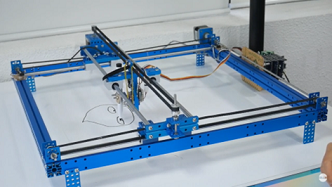
Hero Shots
Final Video
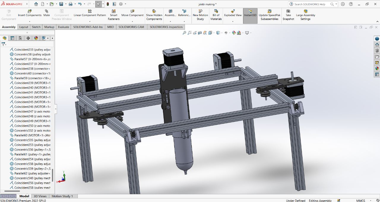
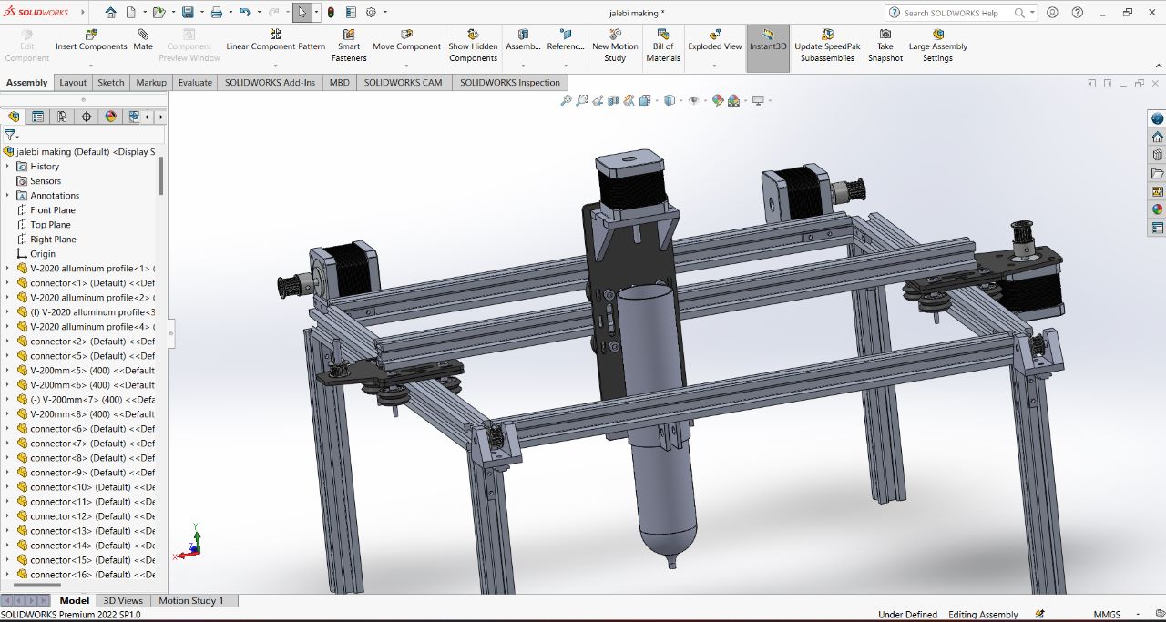
Cad Modelling
My partner design the 3D Model of of our machine using solidworks.
Individual Contribution
Mechanism Selection
We had a strong brain storming on design selection, what kind of mechnism should we use for our machine in order to get desired output.
And after going through different mechism we had came to this mechanism, which is similar like working of 3D Printer
Roles and Responsibility
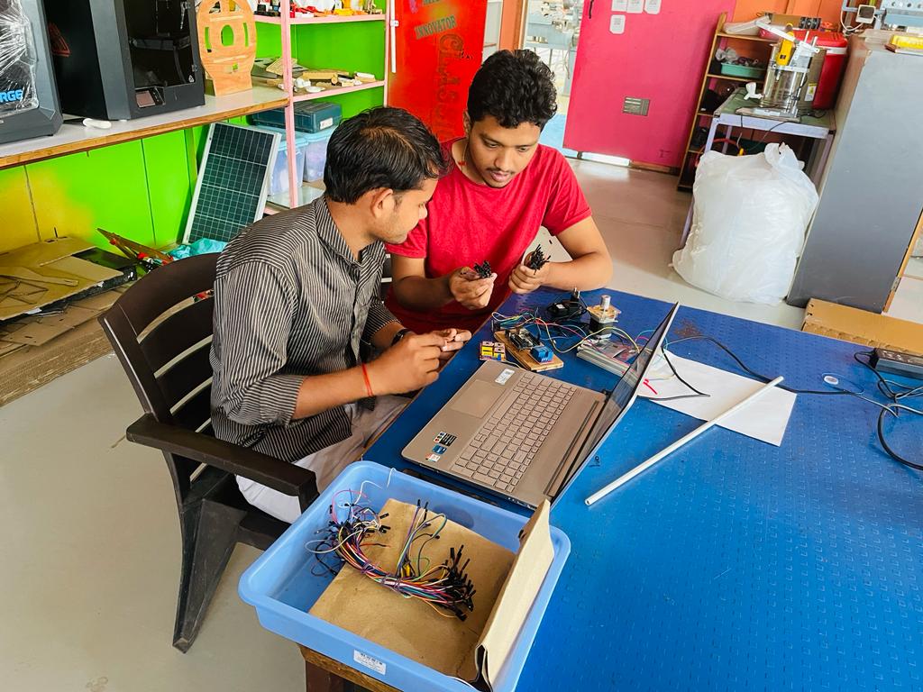
As we are total 2 students from Fab Lab Vigyan Ashram, so we mutually did all the work starting from 3D Modelling, Fabrication, assembly, and electronics work.
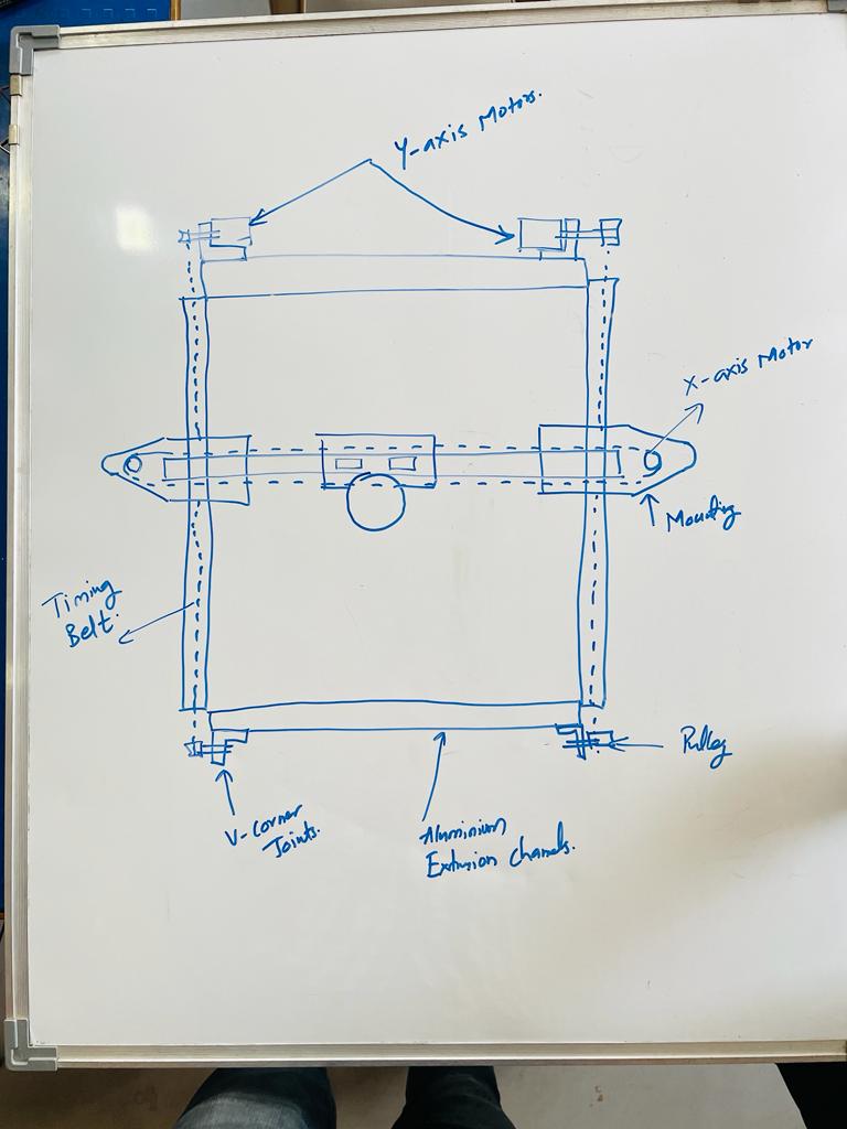
Mechnical Design
Componenet used
Mechanical Components
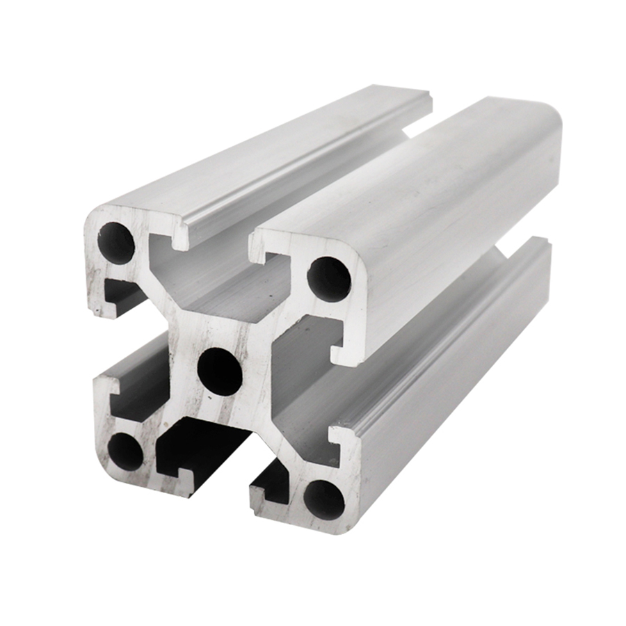
1) Aluminium Extrusion channels
Extruded aluminum channels are also used in framing, creating reveals and for protecting faces or edges of millwork. Our extruded aluminum channels enhance any surface they are applied to and are easy to maintain, clean, and polish. They are the perfect addition to any design project.
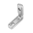
2) Extrusion v Slots joint
The L shape hidden corner bracket is used for setting up a right angle connection of the two aluminum profiles, inserting the two ends of the L bracket into the groove of the profile, and tightening the set screw to fix the two profiles. Built-in connection with beautiful and simple features. Widely used for building industrial aluminum frame structures, 3D printers, CNC routers, laser engravers, and robotics projects.
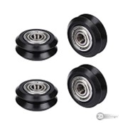
3) Bearing Wheels
This spindle bearing has a special structure with large load capacity, high smoothness, high reliability and good performance. The pulleys with gear have a special antiback function. This gear pulley is suitable for the ordinary printers, very useful and practical. Suitable for most printers on the market, with a wide range of applications and usually used in advertising copiers, printing machines and other industries.
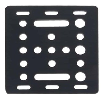
4) V Slot Gantry Plate
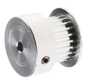
5) Aluminium Pulley
This is GT2 Aluminium Pulley 40 Teeth 5mm Bore 6mm Width. It consists of 40 teeth and 5mm inner bore. The Pulley works great with a GT2 6mm wide timing belt. Two set screws can be used to attach it firmly to any 5mm diameter shaft. This aluminium pulley constructed with high quality aluminium material makes it lustrous and light weighted displaying its high quality strength and durability.
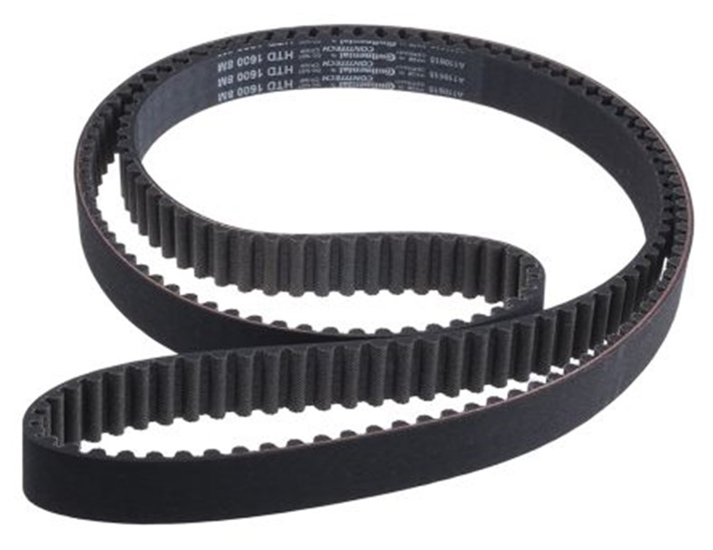
6) Timing Belt
Highest quality precision 10M GT2 Width 6mm Black Open Timing Belt For 3D Printer. Made from NEOPRENE Synthetic Rubber reinforced with fiberglass cords for superior strength. Neoprene an oil-resistant substitute for natural rubber, was invented by DuPont scientists on April 17, 1930.
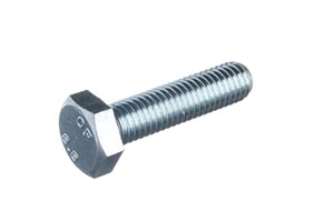
7)M5 Bolts
Electronics
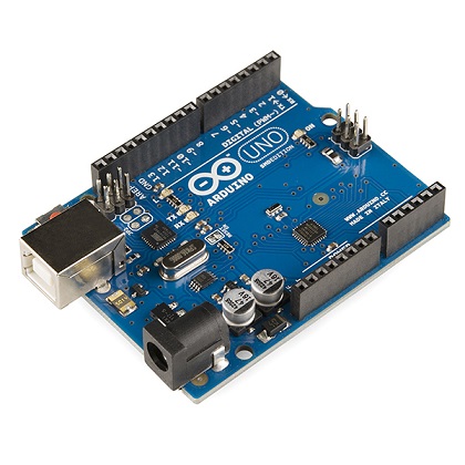
Arduino Uno
The Arduino Uno is an open-source microcontroller board based on the Microchip ATmega328P microcontroller and developed by Arduino.cc and initially released in 2010. The board is equipped with sets of digital and analog input/output pins that may be interfaced to various expansion boards and other circuits.
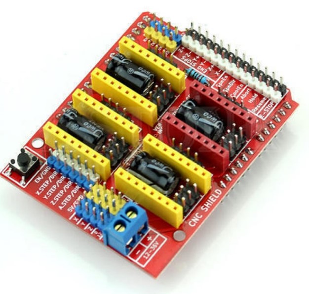
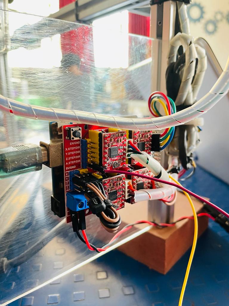
CNC Shield
The CNC Shield V3.0 allows you to build a engraving machine, 3D printer, mini CNC and other similar devices using your Arduino. It is designed as a shield and can plug on top of an Arduino requiring no external connections and wiring. There are 4 slots on the board for plugging in stepper motor drive module which can drive 1 stepper motor each. Controlling each step stepper motor requires only two IO pins on the Arduino. Just insert this Arduino CNC Shield V3.0 onto an Arduino UNO, and install the GRBL firmware, you can then quickly build a DIY CNC engraving machine.
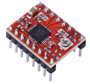
Motor Driver
A4988 Module is a Smaller and Cheapest breakout board for Allegro's A4988 Stepper Motor Driver. It has many advantages including adjustable current limiting, over temperature and over current protection. It has five different stepping resolution and has a wide operating voltage range from 8 volt to 35 volts and can deliver current upto 1 Amp per phase.
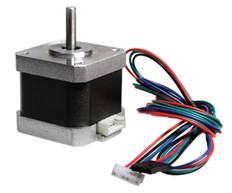
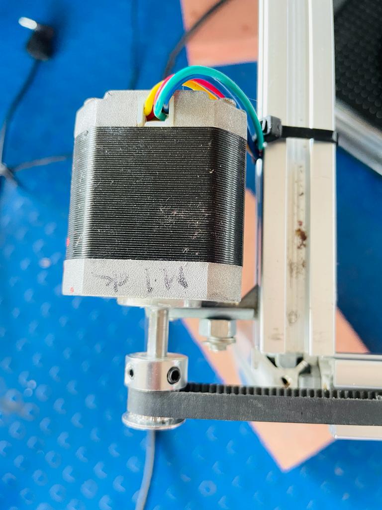
Nema 17 Stepper Motor
The stepper motors move in precisely repeatable steps, hence they are the motors of choice for the machines requiring precise position control. The NEMA17 4.8 kg-cm Stepper Motor can provide 4.8 kg-cm of torque at 2.5A current per phase.The motors position can be commanded to move or hold at one position with the help of Stepper Motor Drivers. The NEMA17 4.8 kg-cm Stepper Motor provides excellent response to starting, stopping and reversing pulses from stepper motor driver.
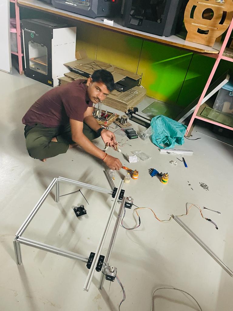
Fabrication
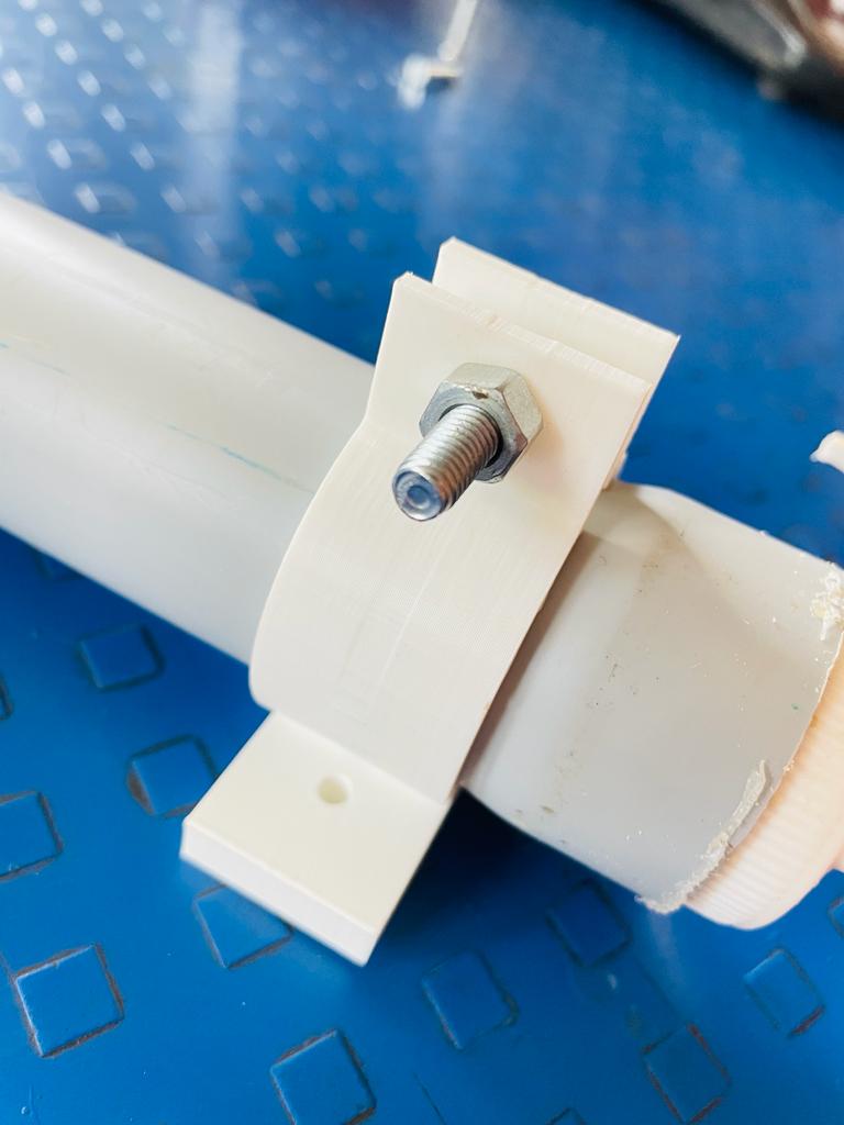
3D Printed Parts
Laser Cutting Parts
Assembly Process
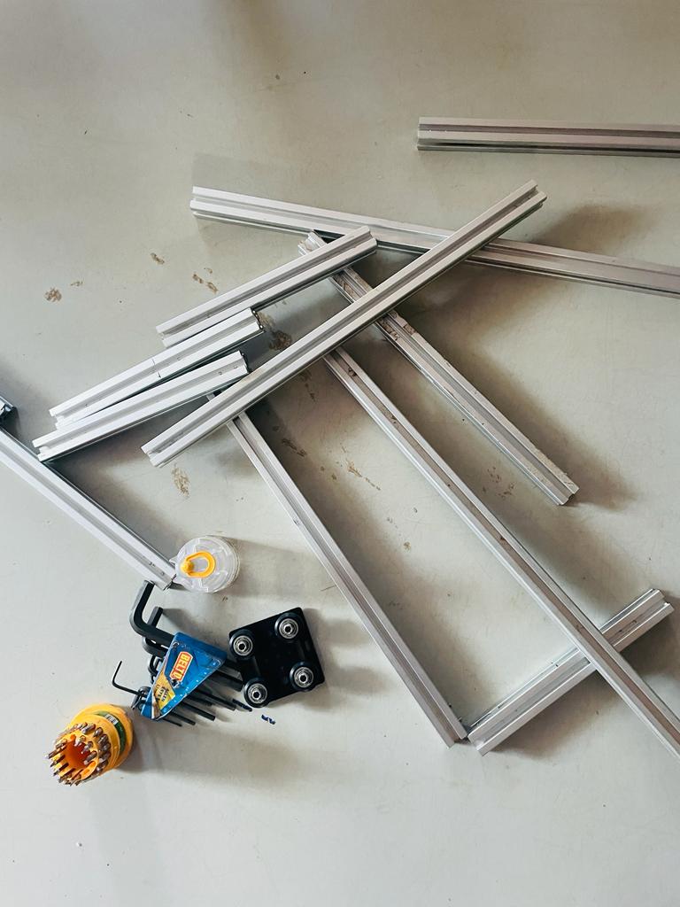
1) Chassis fitting
Used Aluminium extrusion channels to make the basic chassis structure of the machine, We had these channels in Fab’s inventory, we did some machining work in order to get required sizes of aluminium channels.
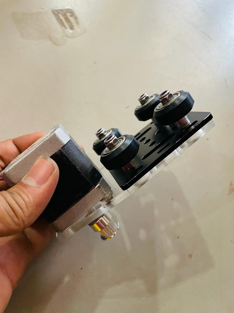
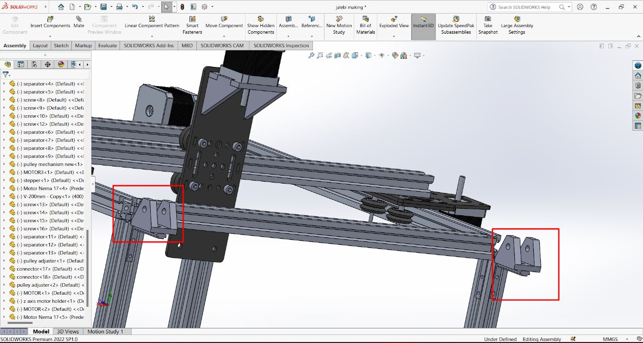
2) Gantry Plate mounting
For Smooth motion of the X & Y axis we used a gantry pate with roller wheels mounted on it. This allows us to achieve smooth and linear flow motion along x & y axis.
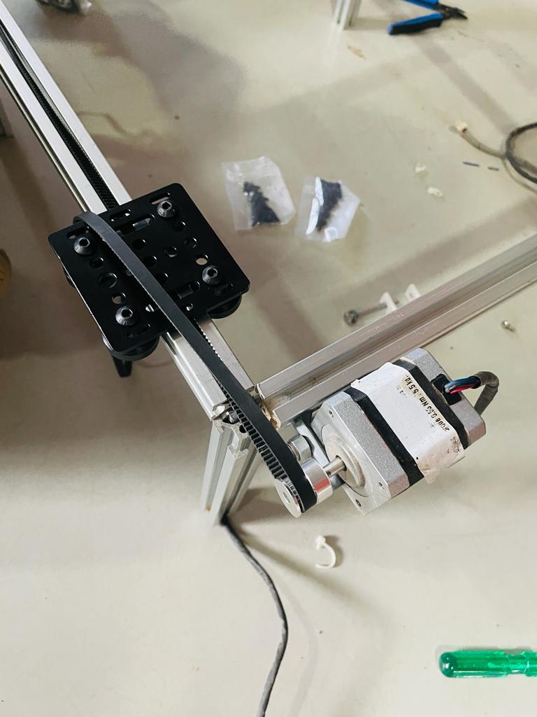
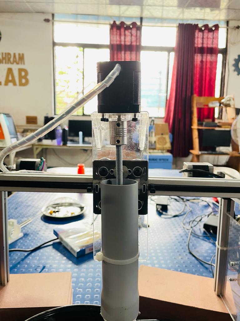
3) Motor fitting
We used 2 stepper motors for Y-axis motion as the axis has to carry a high amount of load. We connect those stepper motors through corner joint clips. and for the x-axis motor mounting, we added an acrylic plate extension.
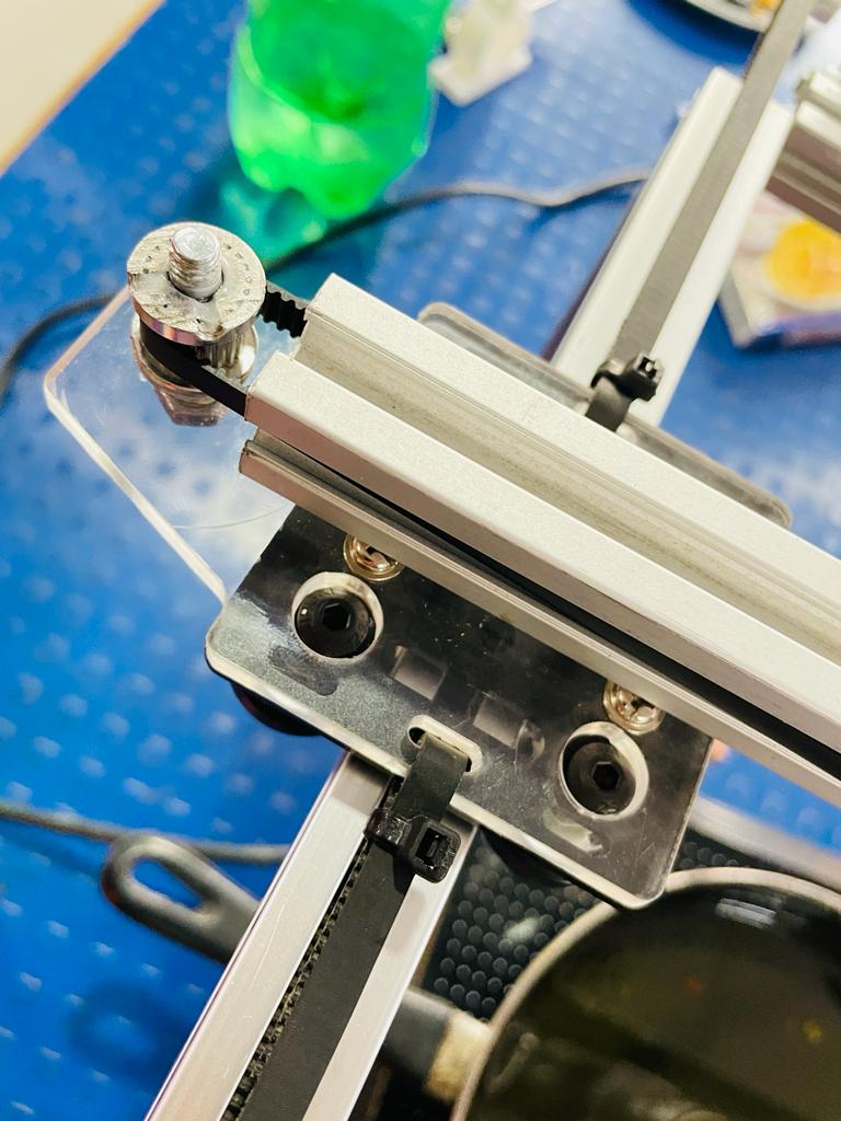
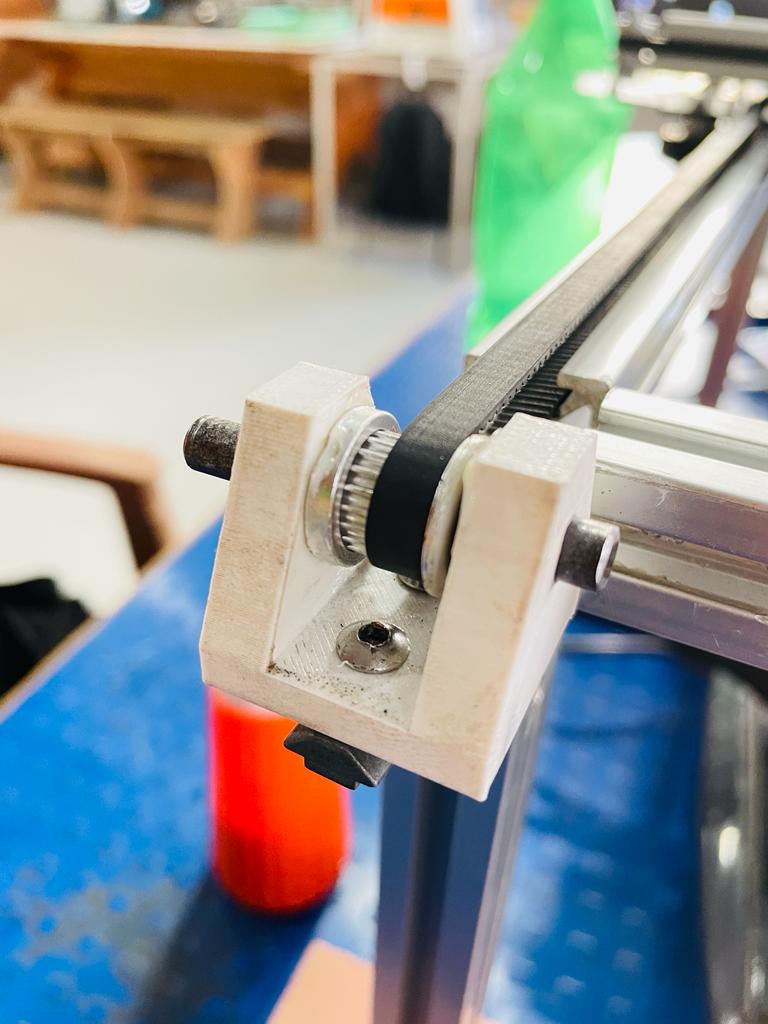
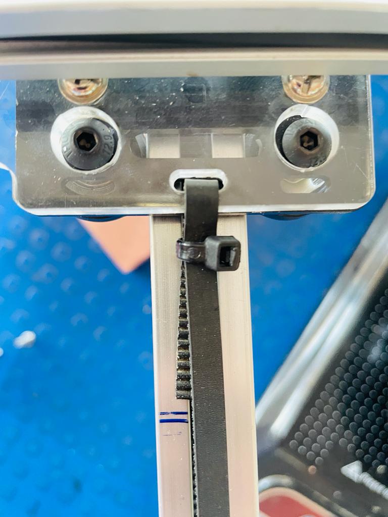
4) Timing Belt & Pulley fitting
For the motion transfer from motor to gantry plate we used threaded pully along with timing belt through motor shaft to gantry plate.
5) Electronic Component Testing
Did completed all the elctronic connection and also tested it
6) Electronics Fitting
Completd all electronic connection and mounted it on to the machine.
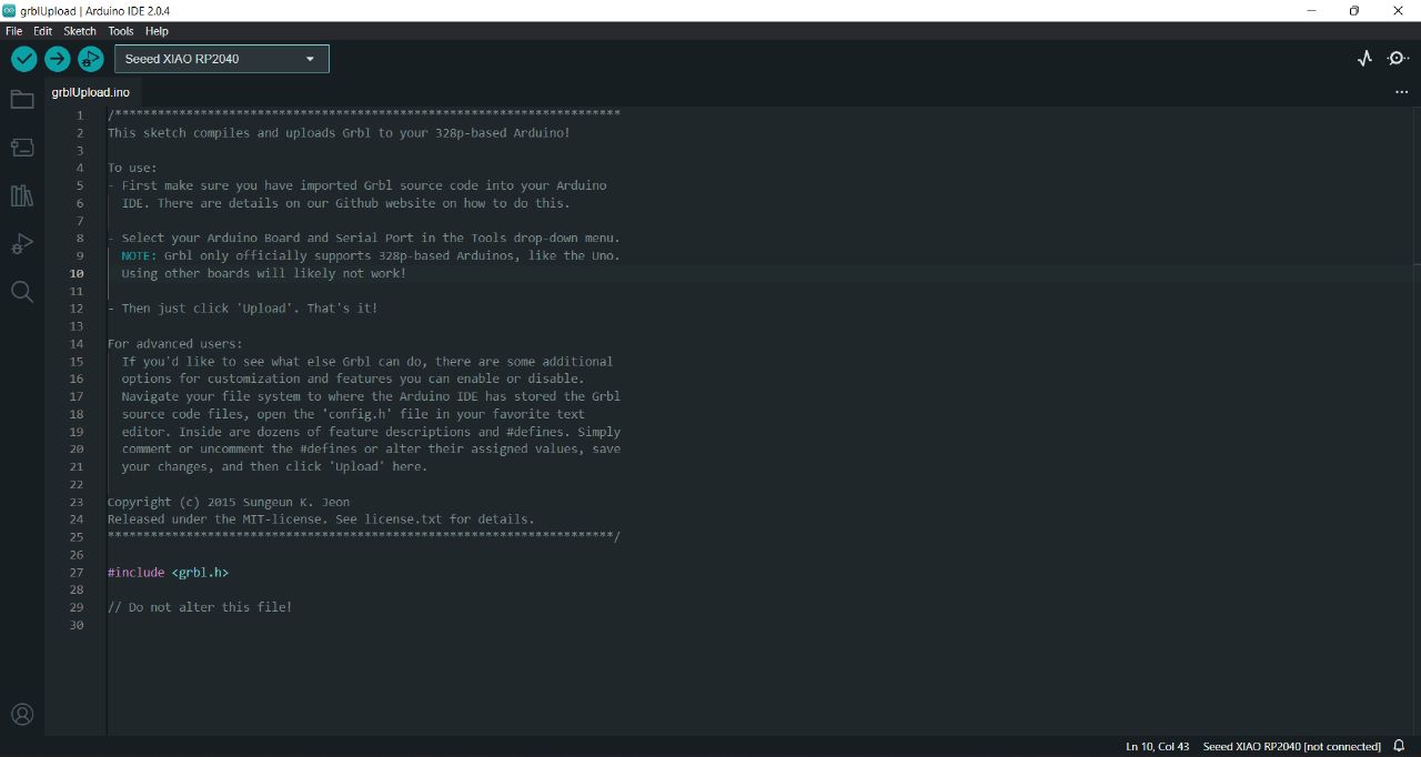
7) GRBL with Arduino UNO
GRBL (pronounced "garble") is an open-source firmware specifically designed for controlling CNC (Computer Numerical Control) machines. It is commonly used with Arduino UNO or compatible boards to drive stepper motors and control the movement of CNC machines like 3D printers, laser engravers, and milling machines.
GRBL is used with Arduino UNO when you want to create a CNC machine or retrofit an existing one. It offers compatibility, performance, ease of use, and community support, making it a popular choice for hobbyists, makers, and small-scale CNC applications.
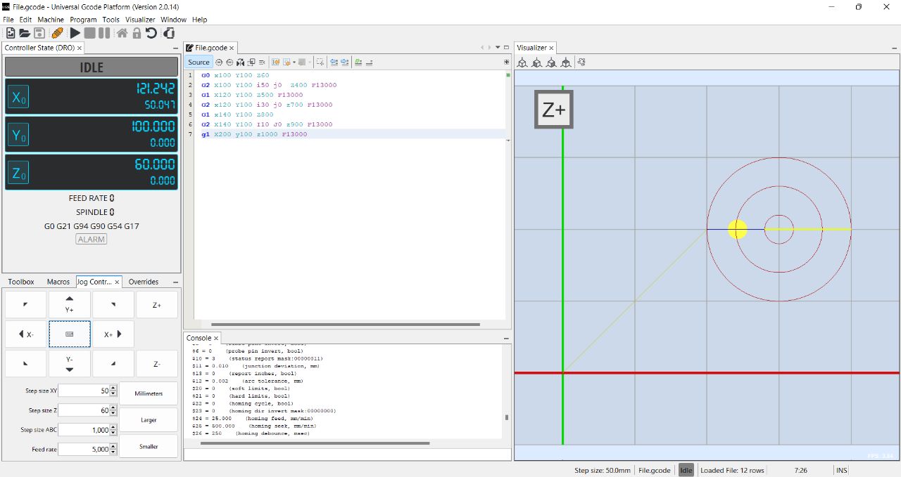
8) Gcode testing with Universal Gcode Sender
Universal Gcode Sender (UGS) is a platform-independent software program used to send G-code commands to CNC machines. It provides a user-friendly interface for controlling and operating CNC machines through a serial connection. UGS can be used with various CNC controllers, including those that utilize GRBL firmware.
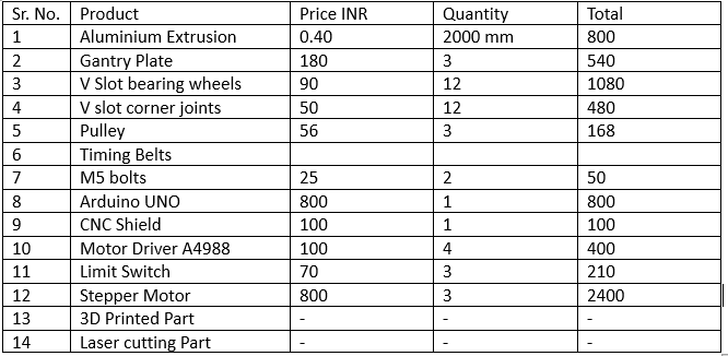
Bill of Material
This below sheet contains details of all the components, their quantity and price.
Learning from this week
1) Can able to use Different Output devices and their programming with arduino ide.
2) able to do soldering of SMD Components
3) Become more familier with electronics
What Went Well
A) Fabrication and machine assembly went extremely well
B) used multiple stepper motors at same time using CNC shield.
Problem Faced
A) unable to get desire output.
B) faced issue with creating Gcode file