Computer Controlled machining
Week 7 Assignement summary
This week I have learned to use CNC Milling machine, Cam nad machine softwares with CNC Milling machine.
Under group assignment activity we understand safety parameters and tested a job in CNC machine available at our Fab Lab.
Here I have documented all of my work with Autodesk Fusion 360 and V carve cam software. I have also documented what went well and where I faced issues in detail.
CNC Router
A computer numerical control (CNC) router is a computer-controlled cutting machine that typically mounts a hand-held router as a spindle used for cutting various materials, such as wood, composites, metals, plastics, glass, and foams. CNC routers can perform the tasks of many carpentry shop machines such as the panel saw, the spindle molder, and the boring machine.
A CNC router is very similar in concept to a CNC milling machine. Instead of routing by hand, tool paths are controlled via computer numerical control. The CNC router is one of many tools with CNC variants.
A CNC router can be used to produce items such as door carvings, interior and exterior decorations, wood panels, sign boards, wooden frames, moldings, musical instruments, and furniture. In addition, they see use in industry in the thermoforming of plastics by automating the trimming process. CNC routers can help ensure part repeatability and sufficiently efficient output for production, or allow one-off designs to be made.
Reference is taken from Wikipedia.
CNC Router at Fab Lab @vigyan Ashram
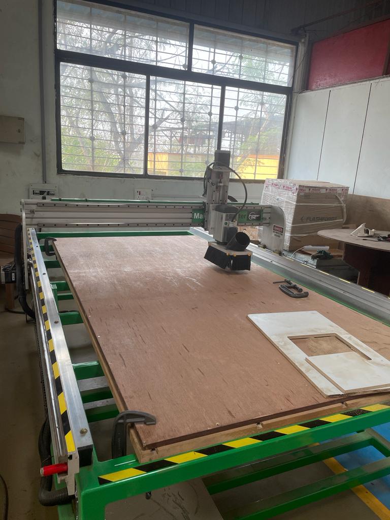
Maker Fab series router includes a control computer with arm, clamping kit, CAD/CAM, MDF Table top with T slot clamping kit, tool Touch Off, and tooling kit.
Include standard MDF table, 3-1/4HP router, wrenches, welded steel frame, dust hood, and starter set of bits that can operate on 110V 20A 8.5” Z Travel The floor space is about 2’ larger than the work area.
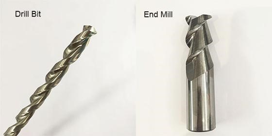
About End Mills & Drill Bits
CNC machining is a subtractive manufacturing method that utilizes cutting tools known as "end mills" to remove material from a workpiece. Although they may resemble drill bits, end mills are much more adaptable and versatile. Nevertheless, in practice, the terms "end mill" and "bit" are often used interchangeably.
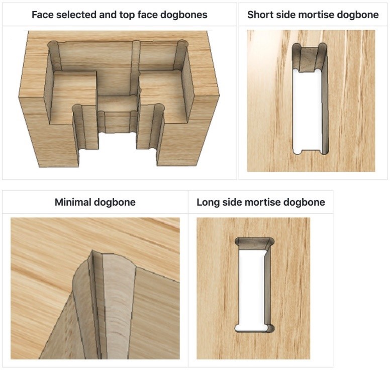
About Dog Bones and their importance.
Design dogbones are small rectangular cuts made at the ends of slots, corners, or other interior angles in a design. They are commonly used in the manufacturing of printed circuit boards (PCBs) and other precision components produced by CNC routing, milling, or laser cutting.
The purpose of designing dogbones is to accommodate the radius of the cutting tool, which creates the internal corners of the cuts. Since cutting tools are round and cannot create perfectly sharp corners, dogbones allow for a precise and accurate fit of components by ensuring that the corners of the cuts are large enough to accommodate the tool's radius.
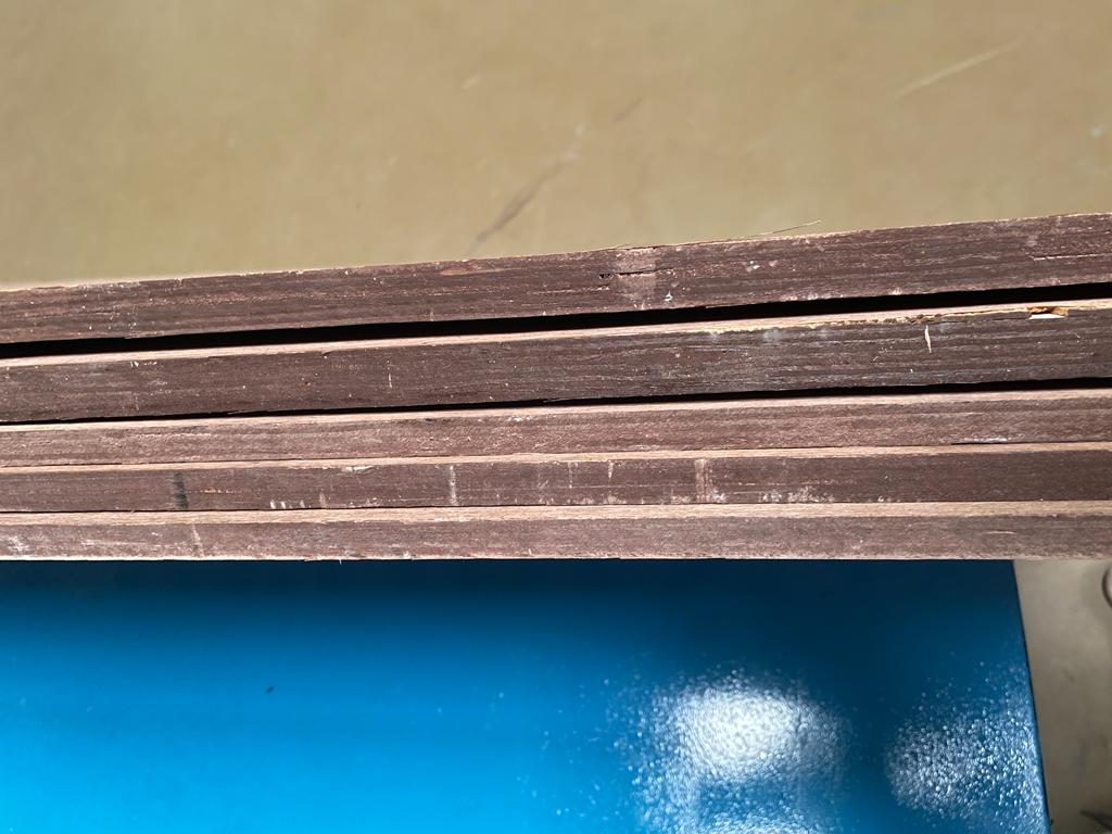
Material @Fab Lab Vigyan Ashram
Plywood is a material manufactured from thin layers or "plies" of wood veneer that are glued together with adjacent layers having their wood grain rotated up to 90 degrees to one another. It is an engineered wood from the family of manufactured boards which includes medium-density fibreboard (MDF), oriented strand board (OSB), and particle board (chipboard).
All Plywoods bind resin and wood fiber sheets (cellulose cells are long, strong, and thin) to form a composite material. This alternation of the grain is called cross-graining and has several important benefits: it reduces the tendency of wood to split when nailed at the edges; it reduces expansion and shrinkage, providing improved dimensional stability; and it makes the strength of the panel consistent across all directions. There is usually an odd number of plies so that the sheet is balanced—this reduces warping. Because plywood is bonded with grains running against one another and with an odd number of composite parts, it has high stiffness perpendicular to the grain direction of the surface ply.
Group Assignement
For this group Assignment we did two activities.
Understand CNC Machine, Safety Parameter and Basic tooling
CNC Machine and Safety Parameters
1) Do not work with a CNC router if you’re tired or sleepy.
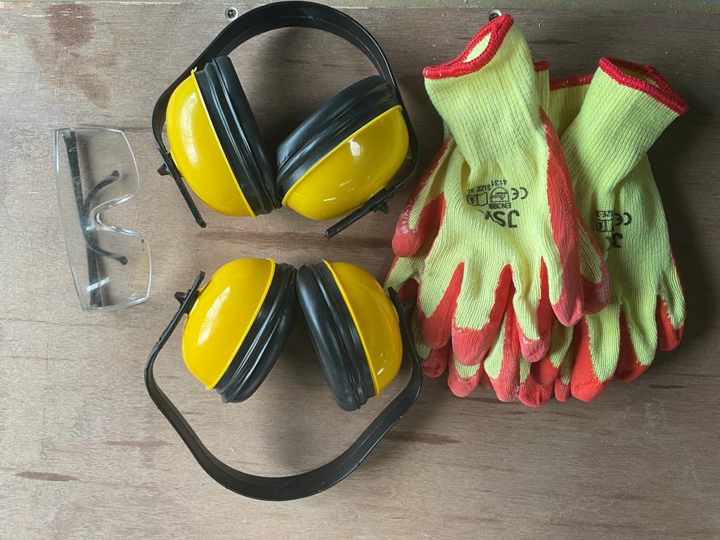
2) Must Wear all the recommended safety equipment.
3) Do not operate the machine unless you are perfectly trained.
4) Beginners should use the machine with Lab Instructor.
5) Try to work in a group. Never work alone.
6) Use Safety Glasses or a face shield
7) Tight your hair, do not keep them loose.
8) Wear Shoes and tight-fit clothes.
9) Listen to changes in machine sound, sometimes unusual noise indicates failure.
10) Work with concentration.
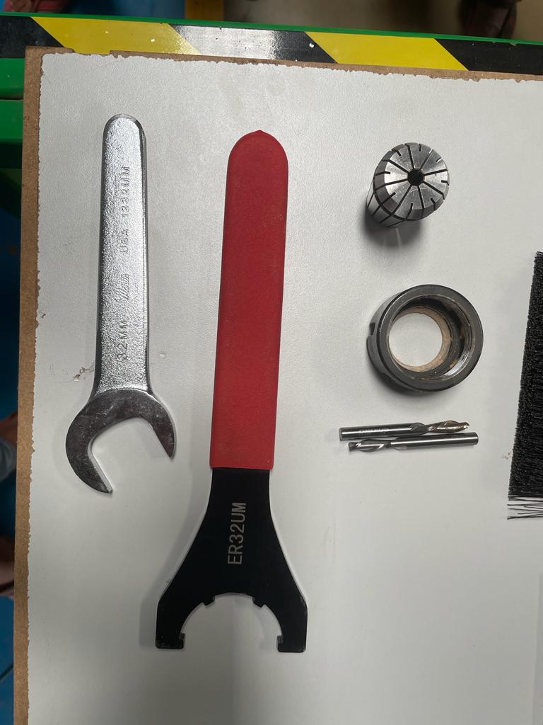
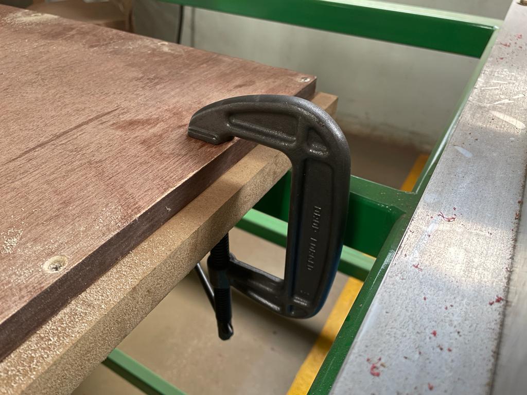
Tooling & Fixture
we have learn to start machine on/off , also have learn to chnage the tool alog with fixture of material to the bed using clamps
Individual Assignment
We need a cupboard to store some material at our Fab lab, so I decided to design and fabricate a workstation that can be used to store material and also it can be utilized for other applications also.
Here, I am going to document all of my individual assignment work from start to end. For this assignment, I used fusion 360 for the parametric design of the workstation, used a v curve to generate the tool path, and used a Maker Fab CNC milling machine for the machining process.
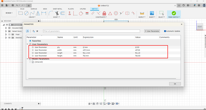
Step 1
Created a new design in fusion 360 and added a few parameters like ply thickness, length width, and height, it helped me to work on this design more faster.
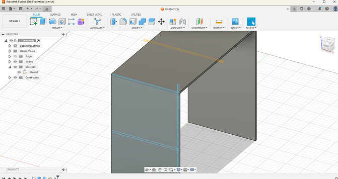
Step 2
Started creating a sketch of the left side of the workstation, adding joints for press-fit joint.
Step 3
Created a construction line and using that line I have replicated my design using mirror command.
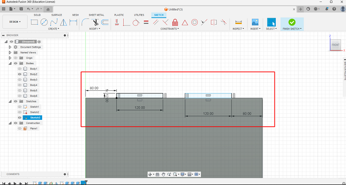
Step 4
Then I added a few compartments and a back side Pannal to it for giving it structure like shelf.
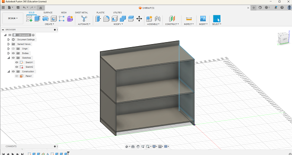
Step 5
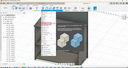
Added slots to each side that are to be joint, and by using combined tool merge all joints and assembly to each other.
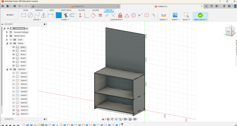
Step 6
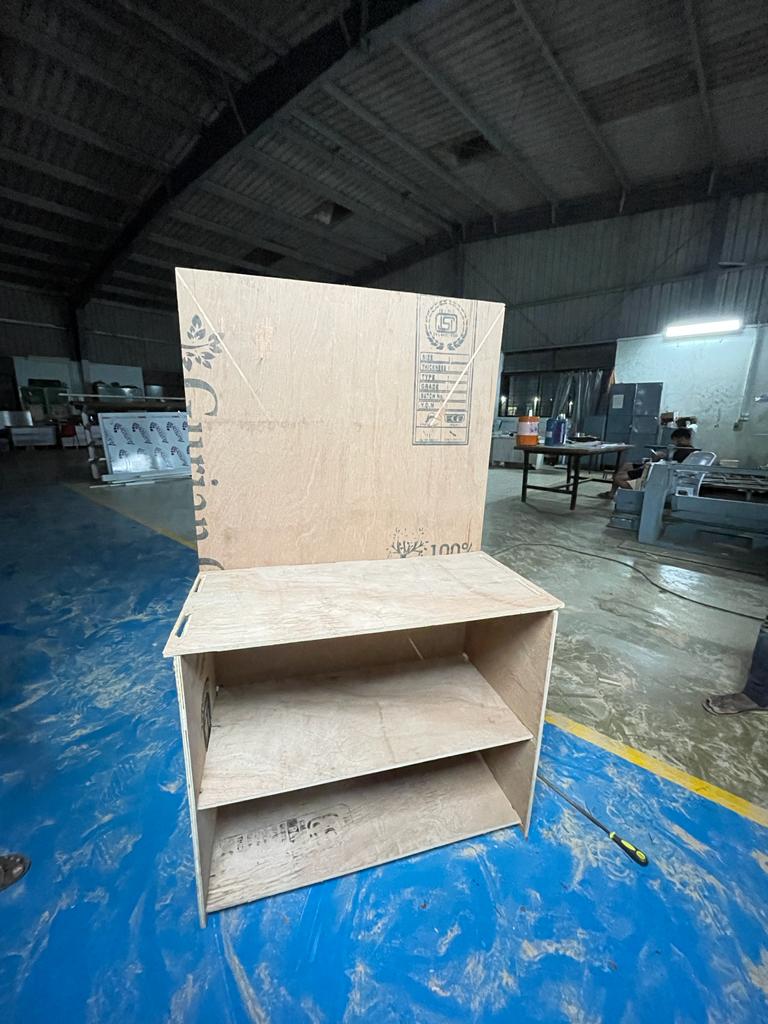
As I wanted to use this table as like mechanical workstation also so I increased the height of back panel by press pulling it.
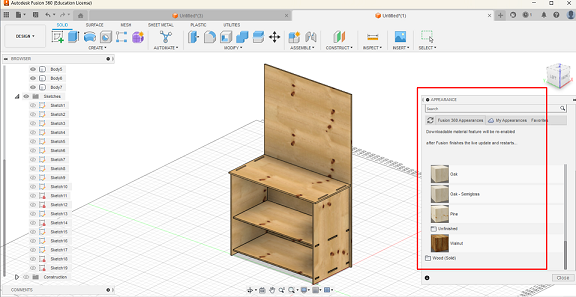
Step 7
Initially, I was designing part considering it as solid geometry and after completing all basic design work, I change the appearance of objects to wood like.
Step 8
As I want to cut all the bodies through a milling machine and I used plywood material with size od 8*4 feet, so I have added 2 different bodies as a replica of 2 standard plywood set.
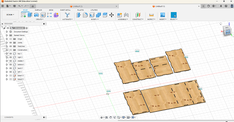
Step 9
Then by fixing those 2 flat surfaces, I did joint the different components of workstation into those at surfaces and rearranged them.
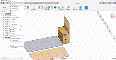
Step 10
EThen by hiding those two flat plywood geometries, I got my components placed horizontally.
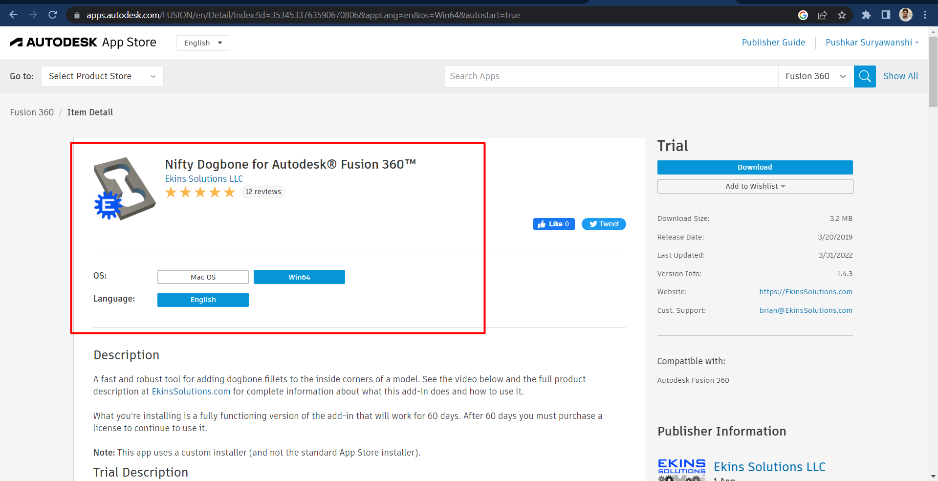
Step 11
To insert slot of one component to another component, dog bones help a lot, but there are one extension application is available for dog bone fillets named as nifty dog bone, I did download it from internet.
Step 12
After successfully installing it I used this function to provide dog bone corner structure to my design.
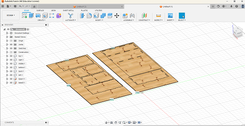
Step 13
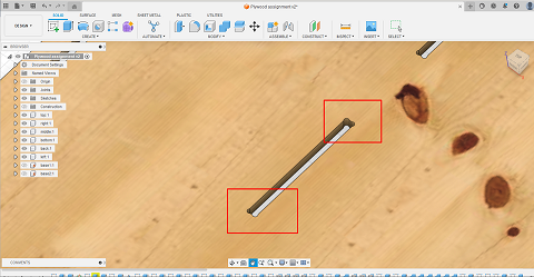
After completing all required design process my final design is look like this. That I have download it in .dwg file format, which can be used for generating tool path.
Step 14
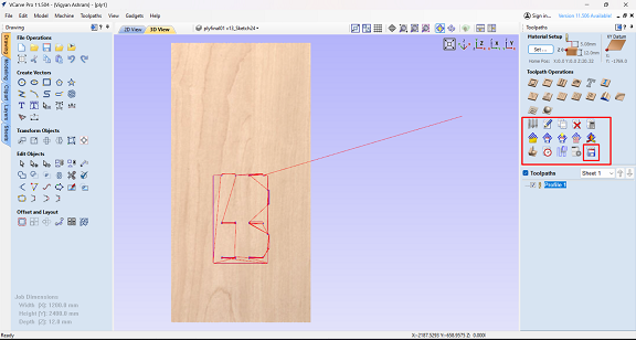
Then for genering tool path for cnc machining i used v carve software.
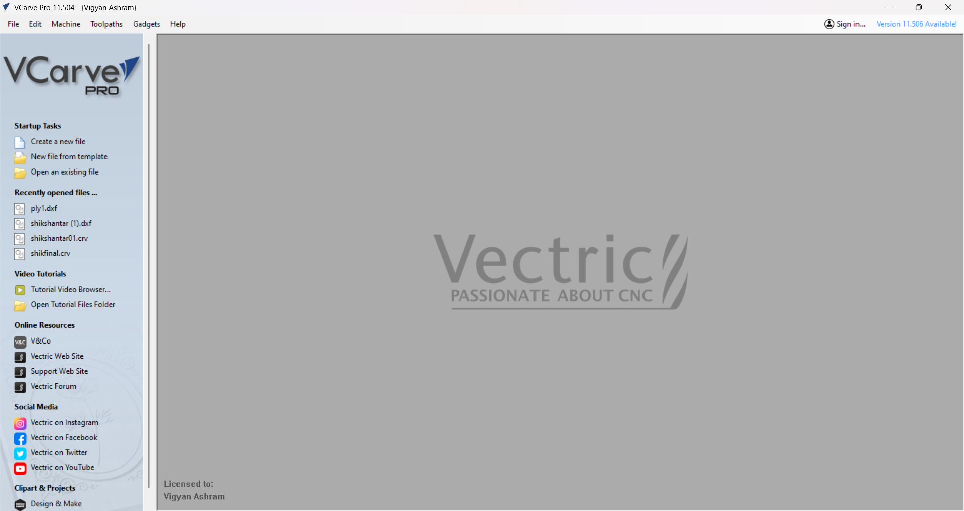
Step 15
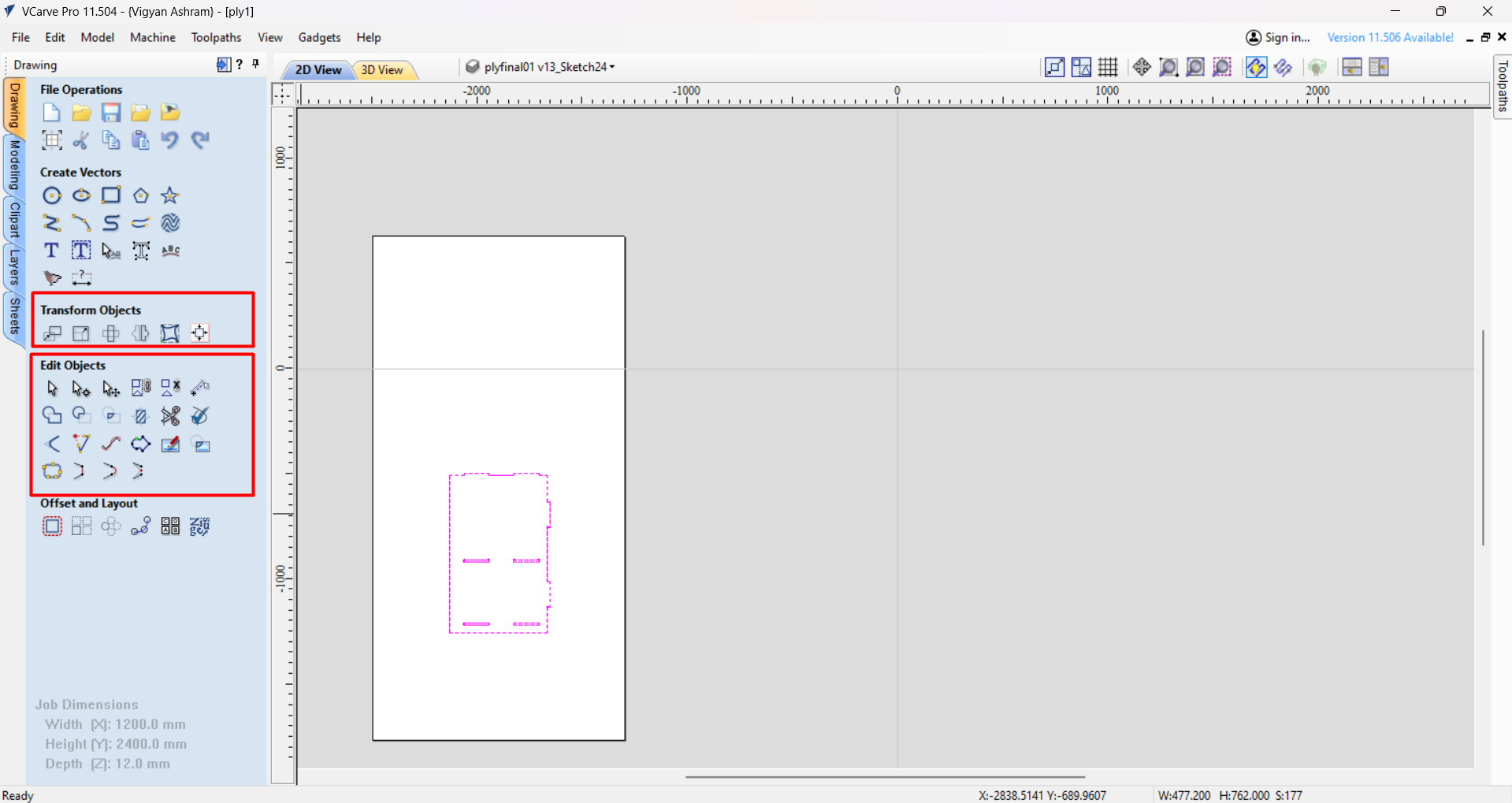
i have opened vcarve software, and uploaded the dxf file into it.
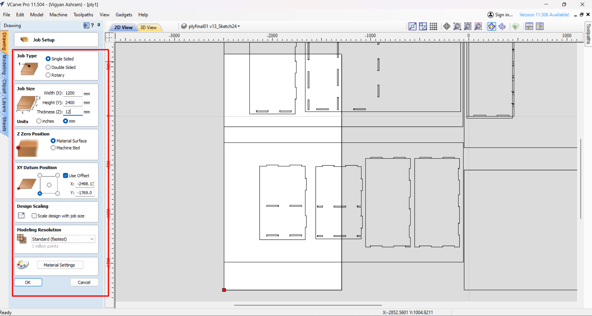
Step 16
Then i did basic setup like, Job size and thickness and material type.
Step 17
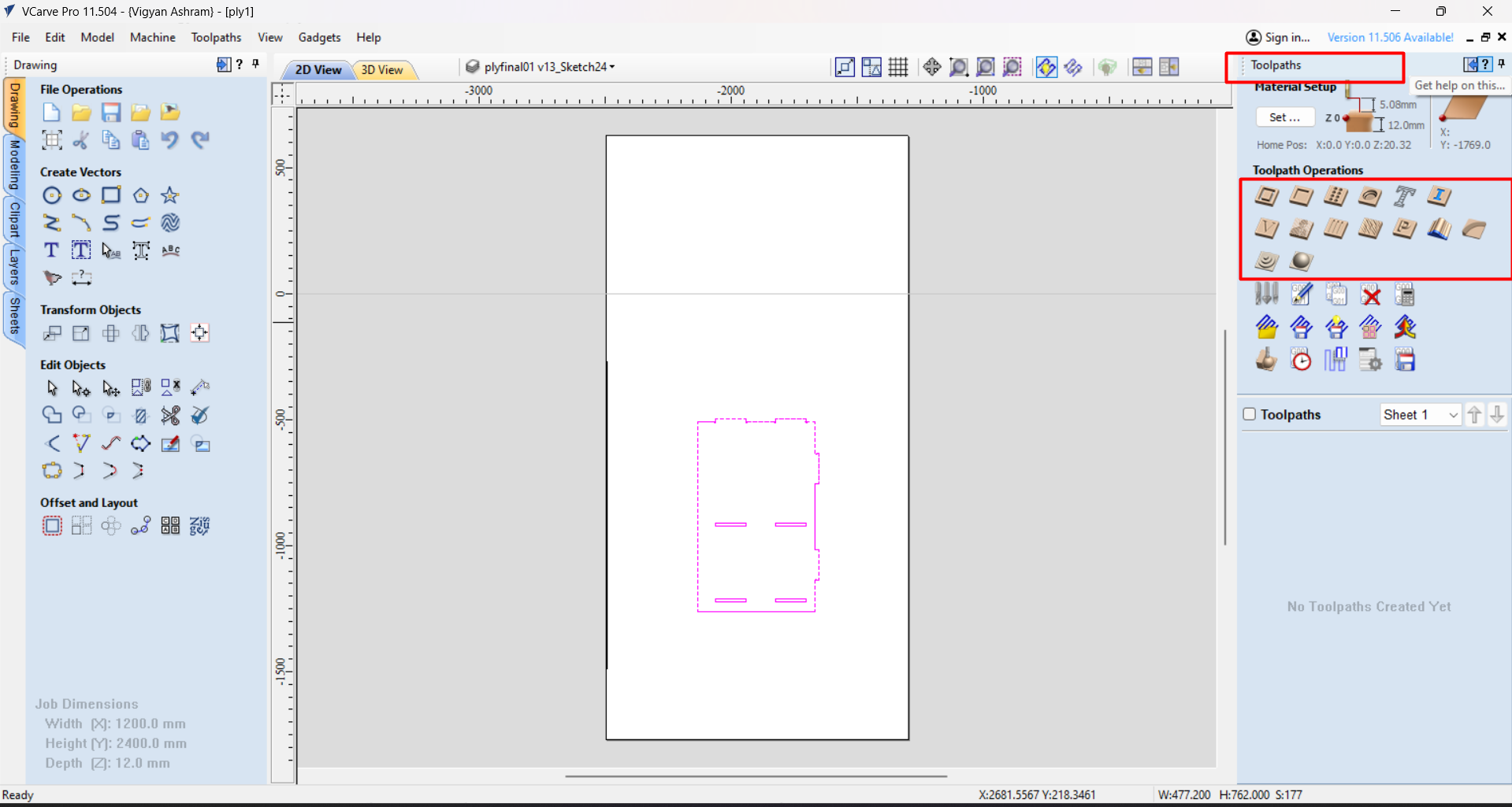
Step i did located and fix the position of the design on the material.
Step 18
Then by selecting the design we need to choose operation.
Step 19
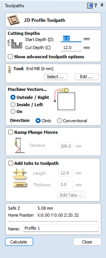
The i put some values for tool path generation like cut depth and no of passes etc.
Step 20
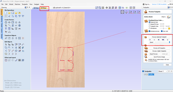
Then by generating tool path, i can preview that toom path in 3D also.
Step 21
Then i have downloaded the tool path in .cnc file format .
FOr the generation of the tool path i used tool with 6 mm of diameter along with spindle speed of 10000 rpm and the feed rate is 27 mm/sec.
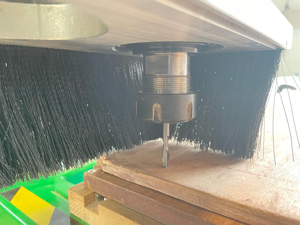
Step 22
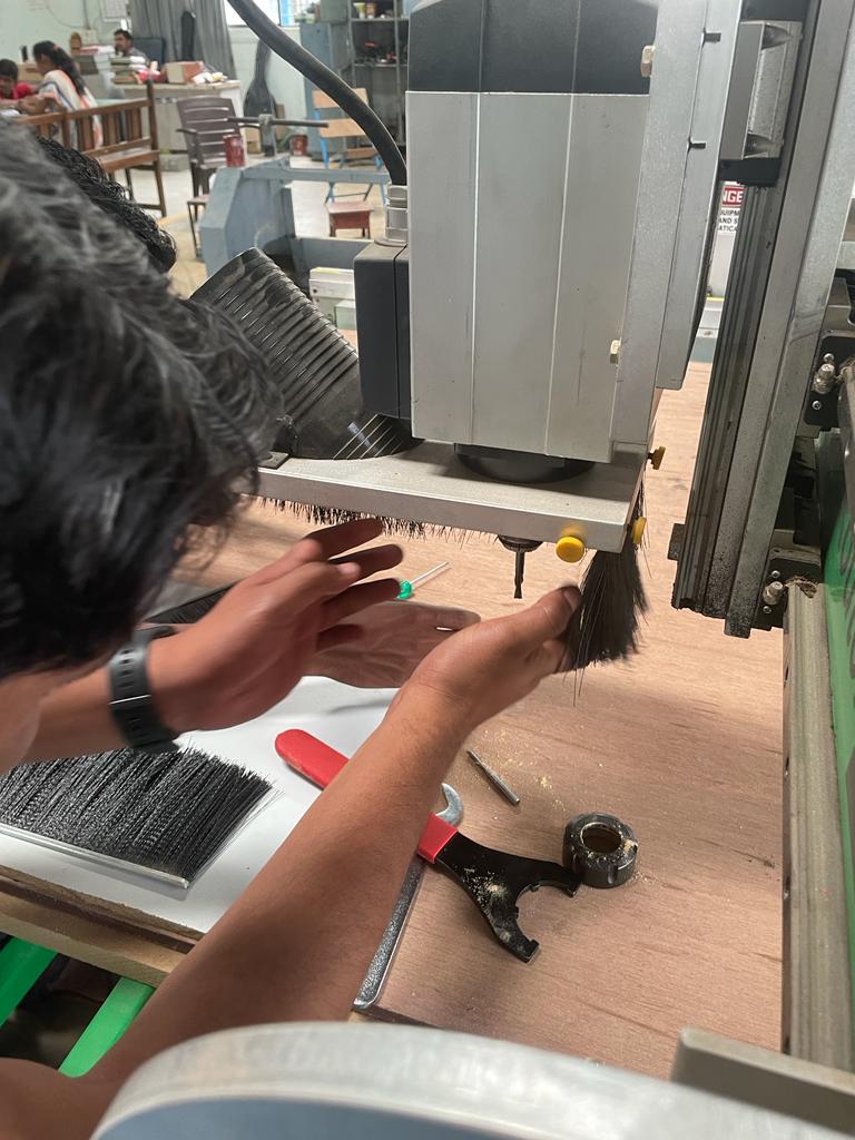
Then by starting the machien i fixed up material and the tool.
Step 23
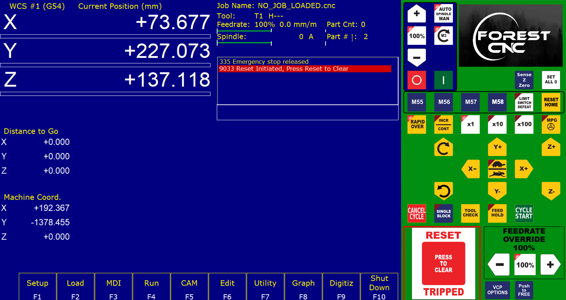
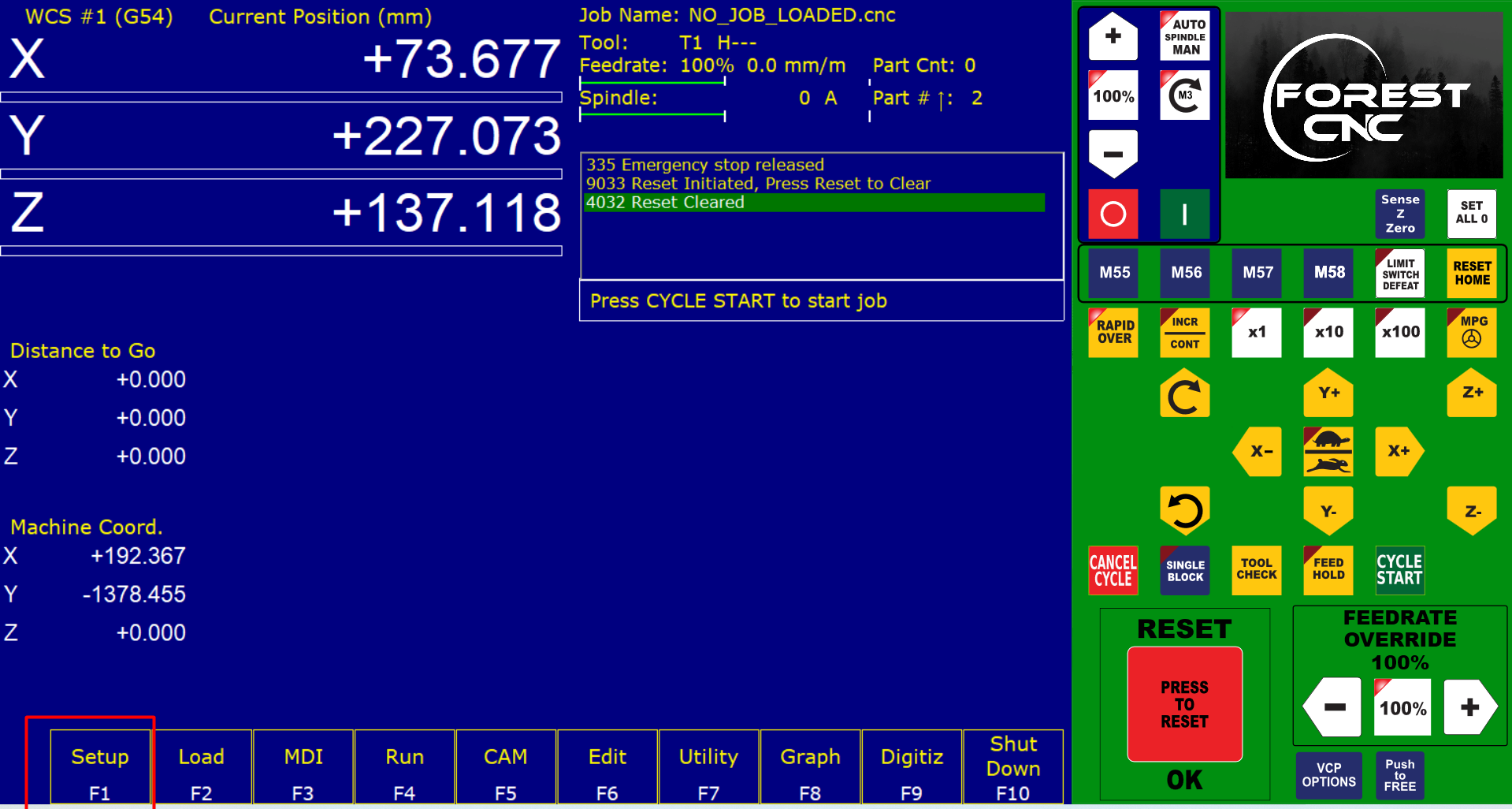
Initiall i reset the machine by clicking on reset button.
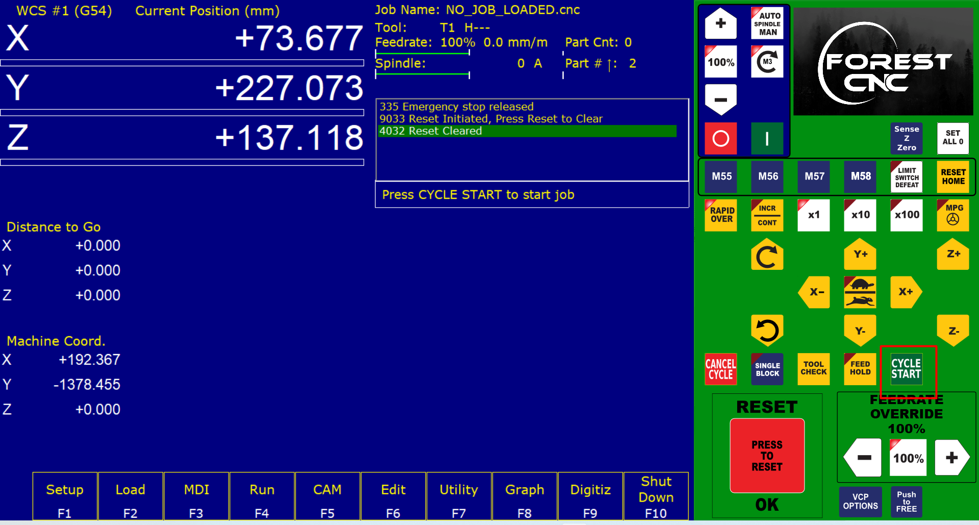
Step 24
Then by clicking on cycle start button, i sent the mchine to home.
Step 25
The manually fixed the new home the machine.
Step 26
Then again i clicked the setup button on the cam software.
Step 27
then set up new home for the design
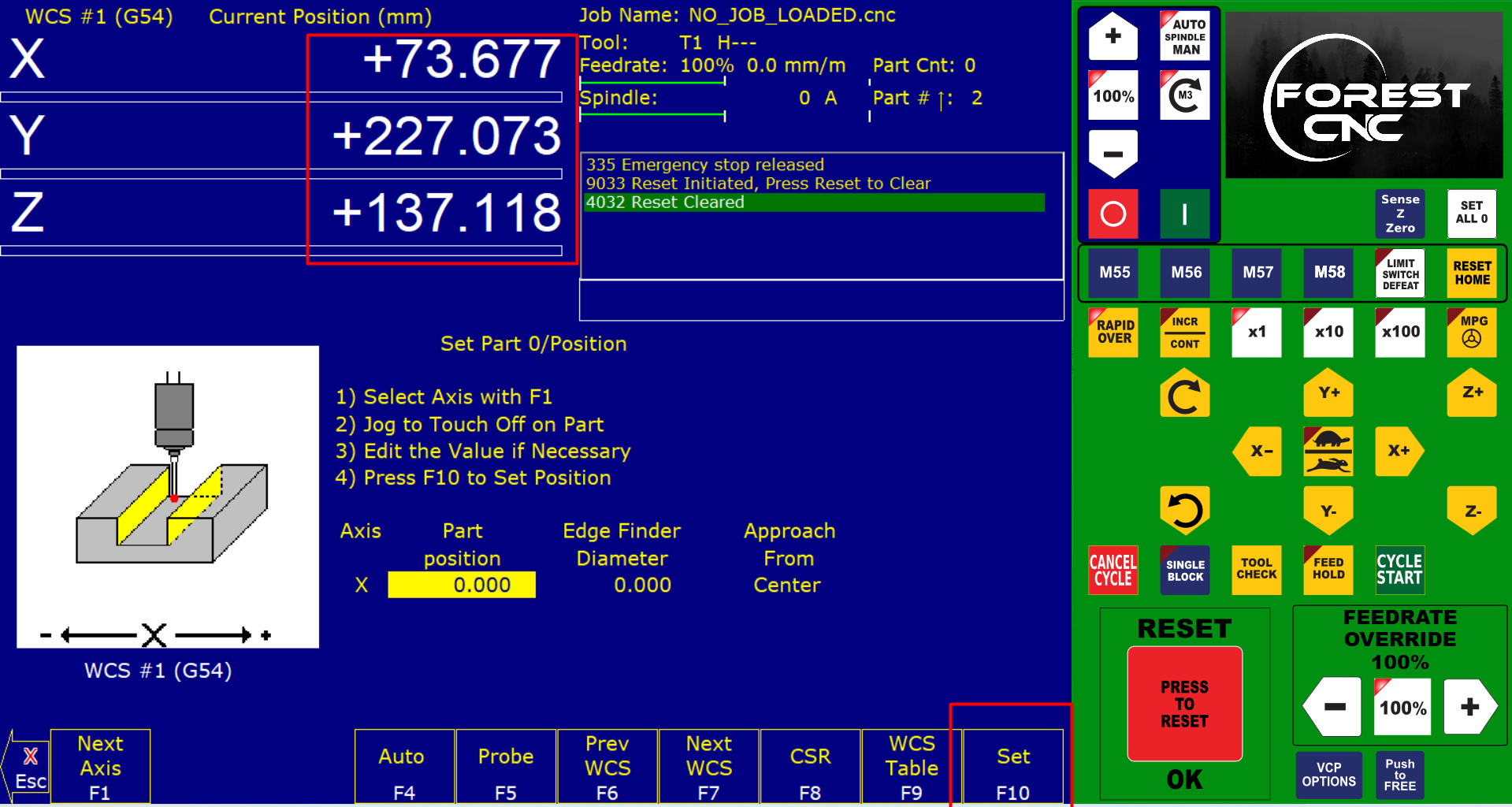
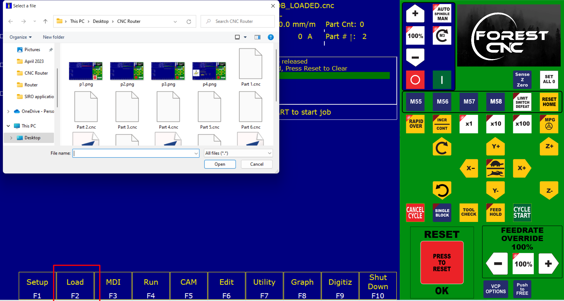
Step 28
Then by cliking the load button i have uploaded the file for cutting.
cutting process
video
Assembly
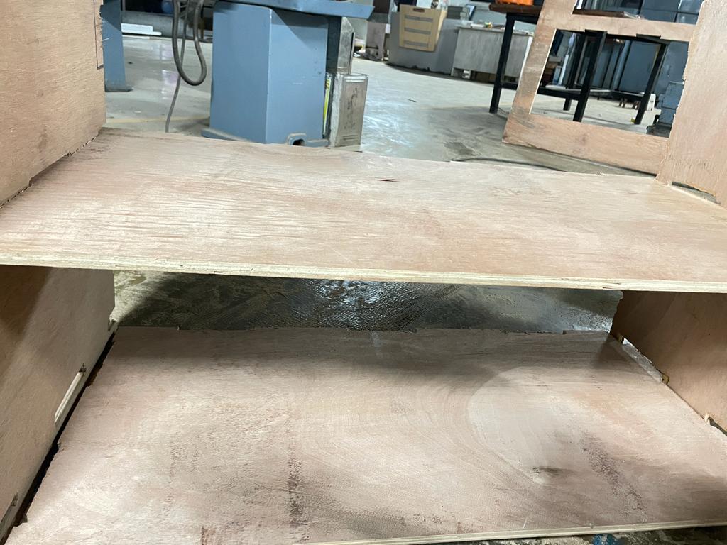
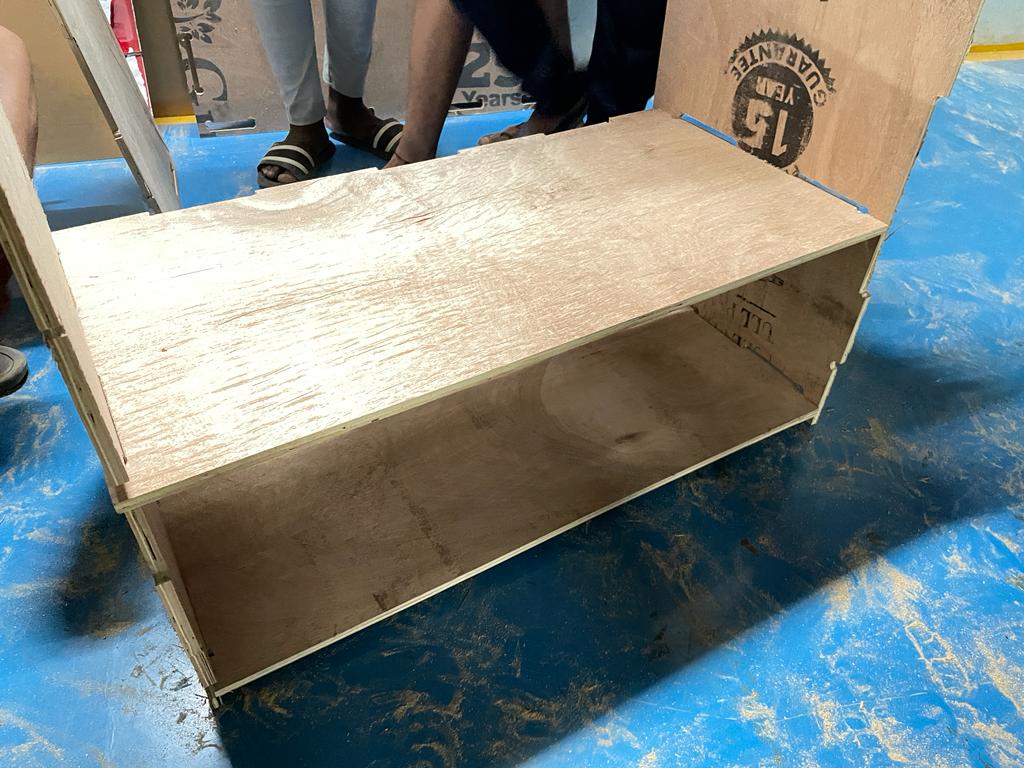
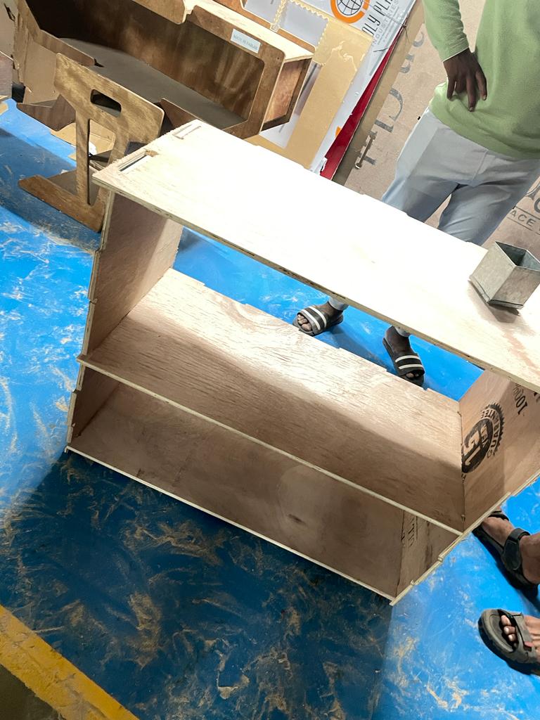
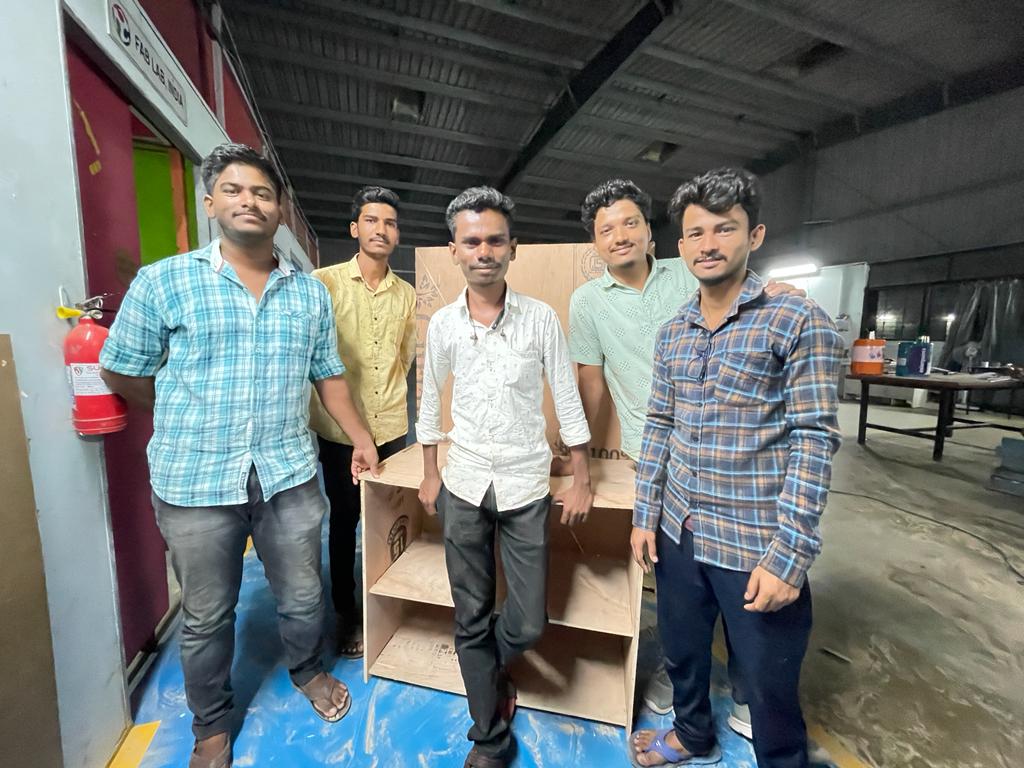
Final Product
Learning from this week
1) Can able to use Parametric design with Fusion 360
2) Use of different softwares like v carve and machine software
3) Bale to use CNC Milling machine
4) Become familier with milling machine and its componets
Problem Faced
1) Faced issue with allotment of dog bones to the corners of joints