Electronics Design
Week 6 Assignement summary
This week I have learned to use different PCB design software like Kicad and Autodesk Eagle. I have also tested lab equipment using different tools.
Here I have documented all of my work with Autodesk Eagle & Kicad software. I have also documented what went well and where I faced issues in detail.
Basics of Electronics
The field of electronics is a branch of physics and electrical engineering that deals with the emission, behavior, and effects of electrons using electronic devices. Electronics uses active devices to control electron flow by amplification and rectification, which distinguishes it from classical electrical engineering, which only uses passive effects such as resistance, capacitance, and inductance to control electric current flow.
History of Electronics
Electronics have hugely influenced the development of modern society. The identification of the electron in 1897, along with the subsequent invention of the vacuum tube which could amplify and rectify small electrical signals, inaugurated the field of electronics and the electron age.[1] Practical applications started with the invention of the diode by Ambrose Fleming and the triode by Lee De Forest in the early 1900s, which made the detection of small electrical voltages such as radio signals from a radio antenna possible with a non-mechanical device.
Bassic terms in Electronics
Current
An electric current is a stream of charged particles, such as electrons or ions, moving through an electrical conductor or space. It is measured as the net rate of flow of electric charge through a surface or into a control volume. The moving particles are called charge carriers, which may be one of several types of particles, depending on the conductor. In electric circuits, the charge carriers are often electrons moving through a wire. In semiconductors, they can be electrons or holes. In an electrolyte, the charge carriers are ions, while in plasma, an ionized gas, they are ions and electrons.
The SI unit of electric current is the ampere, or amp, which is the flow of electric charge across a surface at the rate of one coulomb per second. The ampere (symbol: A) is an SI base unit. Electric current is measured using a device called an ammeter.
Voltage
Voltage, also known as electric pressure, electric tension, or (electric) potential difference, is the difference in electric potential between two points. In a static electric field, it corresponds to the work needed per unit of charge to move a test charge between the two points. In the International System of Units, the derived unit for voltage is named volt.
The voltage between points can be caused by the build-up of electric charge (e.g., a capacitor), and from an electromotive force (e.g., electromagnetic induction in generators, inductors, and transformers. On a macroscopic scale, a potential difference can be caused by electrochemical processes, the pressure-induced piezoelectric effect, and the thermoelectric effect.
A voltmeter can be used to measure the voltage between two points in a system. Often a common reference potential such as the ground of the system is used as one of the points. A voltage can represent either a source of energy or the loss, dissipation, or storage of energy.
Resistance
Resistance to electricity–that is, electrical resistance–is a force that counteracts the flow of current. In this way, it serves as an indicator of how difficult it is for current to flow. Resistance values are expressed in ohms (Ω).
Electricity will flow from high to low when an electron differential exists between two terminals. Resistance counteracts that flow. The greater the resistance, the lower the current. Conversely, the lower the resistance, the greater the current.
What are resistors?
Resistors are electronic components that resist the flow of electricity in a circuit. Resistors are used in electric circuits to adjust current and voltage, much like faucets are used to adjust the tap water flow. They can be used not only to control the flow of current but also to distribute voltage in a circuit.
Electronic circuits need resistors in order to operate under appropriate conditions. Resistors are made of materials that resist the flow of electricity as it passes through them. In this way, they can control the flow of current throughout a circuit. When the current is reduced by a resistor, the surplus electrical energy is converted into heat.
DC series and Parallel circuits
Circuits consisting of just one battery and one load resistance are very simple to analyze, but they are not often found in practical applications. Usually, we find circuits where more than two components are connected together. There are two basic ways in which to connect more than two circuit components: series and parallel.
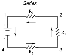
Series
Here, we have three resistors (labeled R1, R2, and R3), connected in a long chain from one terminal of the battery to the other. (It should be noted that the subscript labeling -- those little numbers to the lower-right of the letter "R" -- are unrelated to the resistor values in ohms. They serve only to identify one resistor from another.) The defining characteristic of a series circuit is that there is only one path for electrons to flow. In this circuit, the electrons flow in a counter-clockwise direction, from point 4 to point 3 to point 2 to point 1 and back around to 4.
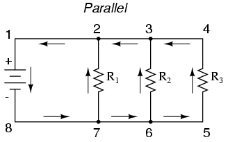
Parallel
Again, we have three resistors, but this time they form more than one continuous path for electrons to flow. There's one path from 8 to 7 to 2 to 1 and back to 8 again. There's another from 8 to 7 to 6 to 3 to 2 to 1 and back to 8 again. And then there's a third path from 8 to 7 to 6 to 5 to 4 to 3 to 2 to 1 and back to 8 again. Each individual path (through R1, R2, and R3) is called a branch.
The defining characteristic of a parallel circuit is that all components are connected between the same set of electrically common points. Looking at the schematic diagram, we see those points 1, 2, 3, and 4 are all electrically common. So are points 8, 7, 6, and 5. Note that all resistors as well as the battery are connected between these two sets of points.
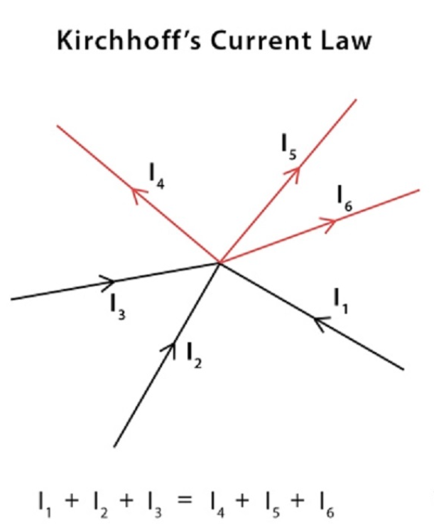
Kirchhoffs Current Law
This law also called Kirchhoff's first law, or Kirchhoff's junction rule, states that, for any node (junction) in an electrical circuit, the sum of currents flowing into that node is equal to the sum of currents flowing out of that node; or equivalently
The algebraic sum of currents in a network of conductors meeting at a point is zero.
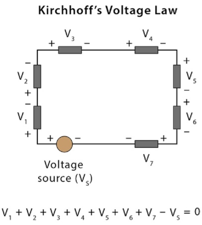
kirchhoff's law of voltage
According to Kirchhoff's Voltage Law, The voltage around a loop equals the sum of every voltage drop in the same loop for any closed network and equals zero. Put differently, the algebraic sum of every voltage in the loop has to be equal to zero and this property of Kirchhoff's law is called conservation of energy.
Group Assignement
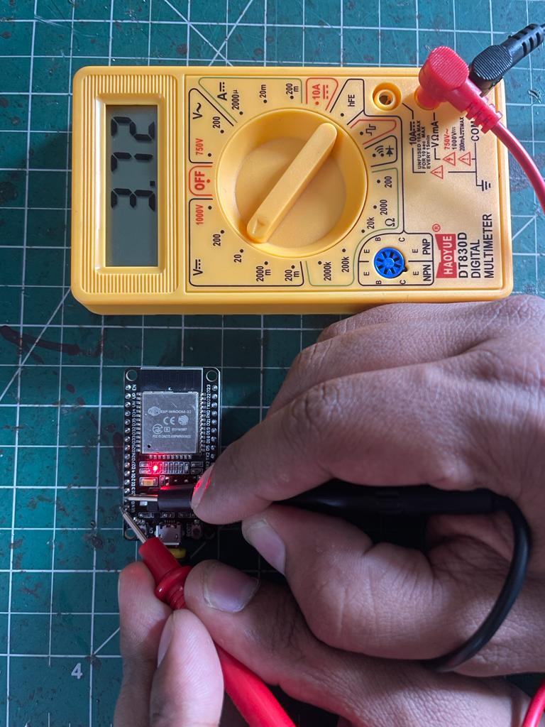
The objective of the Group Assignment is to determine and check the current and voltage of a microcontroller that we have to use for designing of development board using microcontrollers.
Group Assignment Summary:
For this particular assignment, we tested the ESP32 microcontroller’s voltage and current using different measuring devices like a Multimeter and oscilloscope.
Measureing Devices
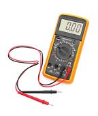
Multimeter
A multimeter or a multitester, also known as a volt/ohm meter or VOM, is an electronic measuring instrument that combines several measurement functions in one unit. A typical multimeter may include features such as the ability to measure voltage, current and resistance.
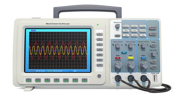
Oscilloscope
An oscilloscope is an instrument that graphically displays electrical signals and shows how those signals change over time. Engineers use oscilloscopes to measure electrical phenomena and quickly test, verify, and debug their circuit designs. The primary function of an oscilloscope is to measure voltage waves.
Using the test equipments in our Lab
We have tested and observed the operation of microcontroller circuit board by using test equipments available in out lab.
Individual Assignement
Design a development board to interact and communicate with the microcontroller.
Individual Assignement summary
For this individual assignment, I designed a development board for LED Blinking using PCB design software named Autodesk Eagle.for this board, I have used an ESP32 microcontroller with other components like LEDs and resistors, etc.
Components Used for Designing
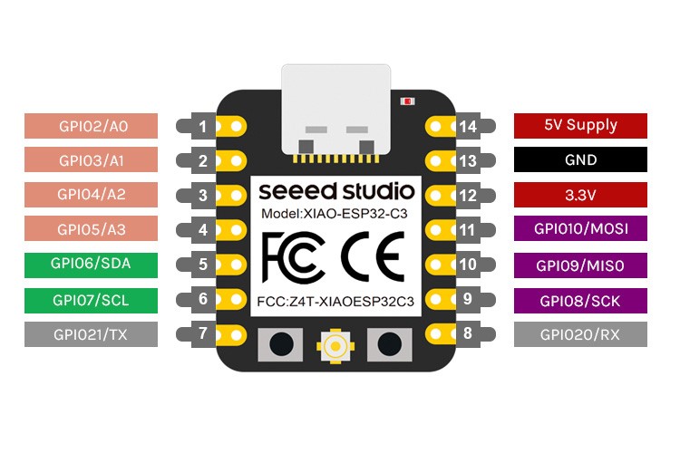
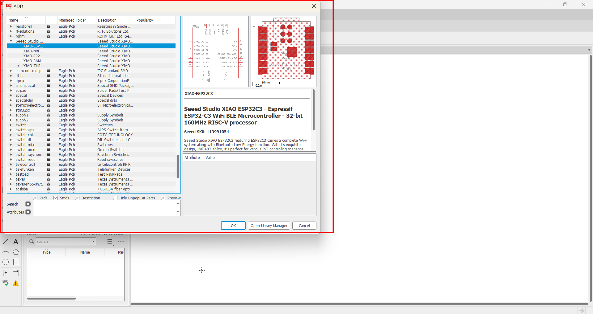
Xiao ESP32 C3
Seeed Studio XIAO ESP32C3 featuring ESP32C3 carries a complete Wi-Fi system along with Bluetooth Low Energy function. With its exquisite design and WiFi+BT ability, it's perfect for various IoT controlling scenarios and complex carriable applications. The board equips highly-integrated ESP3 C3
LEDs
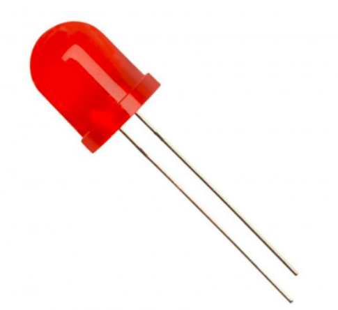
A light-emitting diode is a semiconductor device that emits light when current flows through it. Electrons in the semiconductor recombine with electron holes, releasing energy in the form of photons. The color of the light is determined by the energy required for electrons to cross the band gap of the semiconductor.White light is obtained by using multiple semiconductors or a layer of light-emitting phosphor on the semiconductor device.
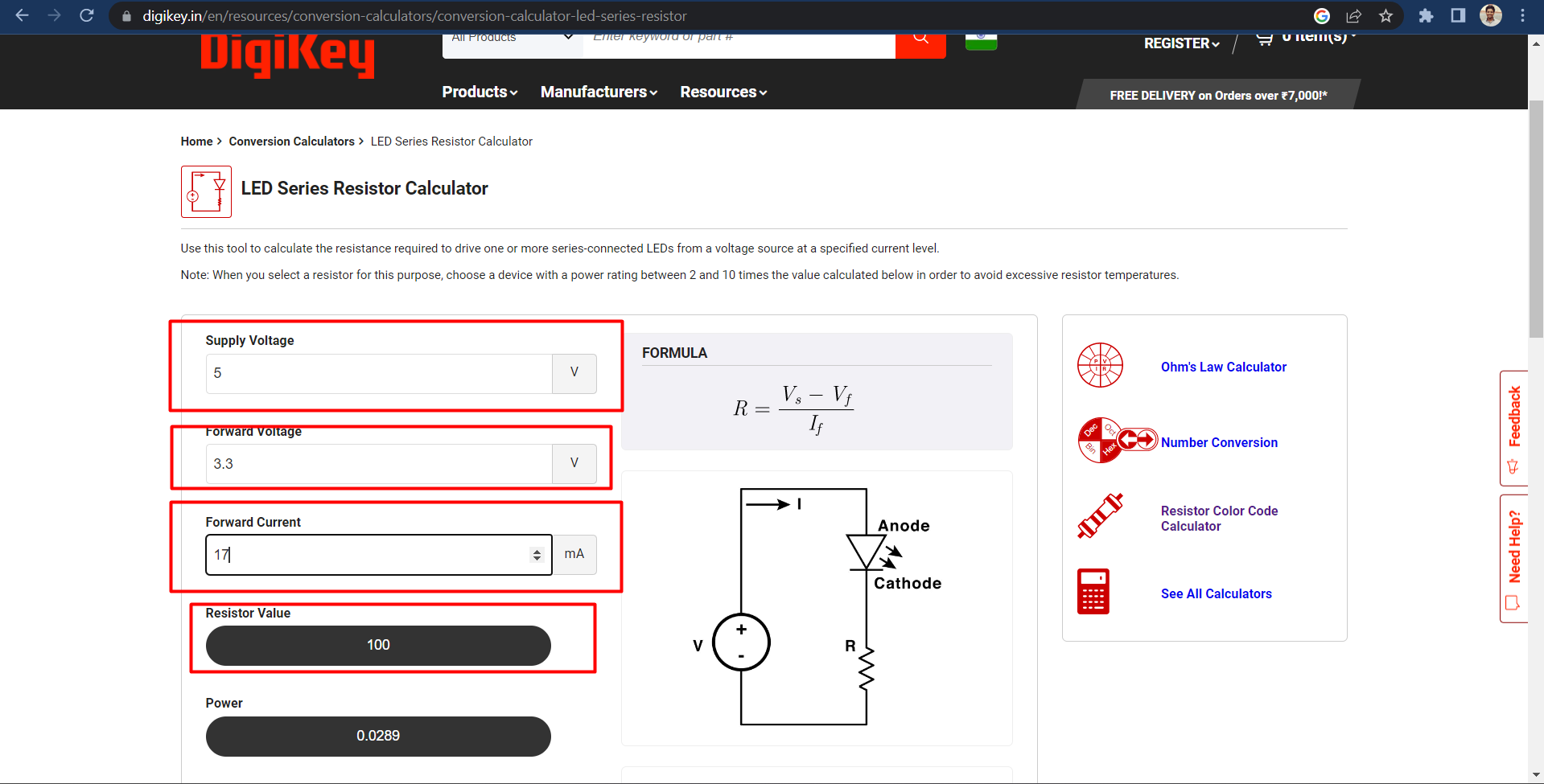
For this assignement i have used 3.3v led
Resistors
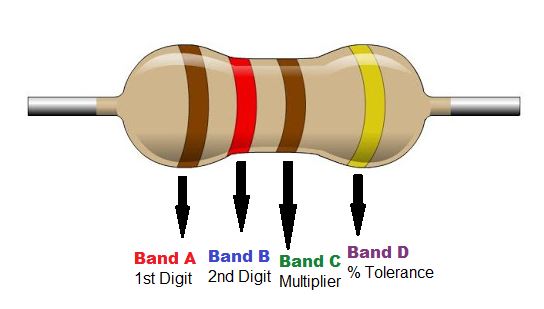
A resistor is a passive two-terminal electrical component that implements electrical resistance as a circuit element. In electronic circuits, resistors are used to reduce current flow, adjust signal levels, to divide voltages, bias active elements, and terminate transmission lines, among other uses.
For this assignement i have used 100 ohm resistor
Steps to Design Developement Board
Step 1
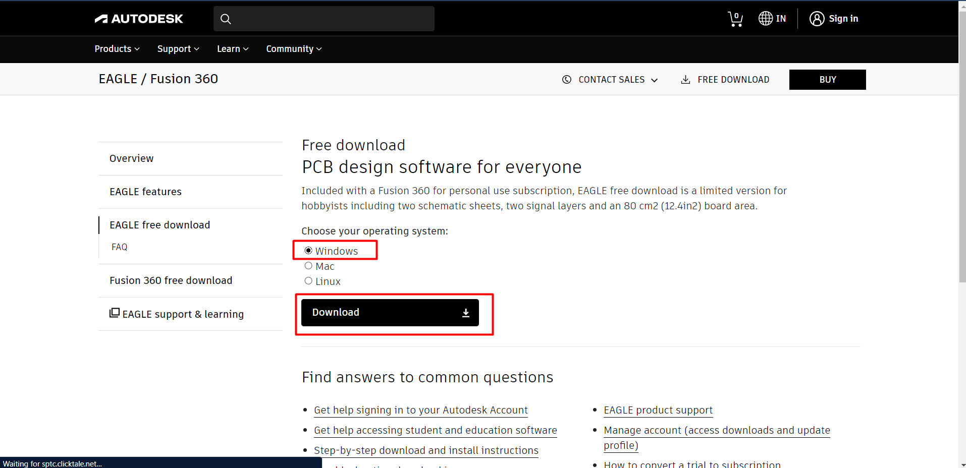
Downloaded Autodesk eagle software for the Windows operating system from the Autodesk website. Then by installing it have log into it by my Autodesk login credentials which I have used for operating fusion 360.
Step 2
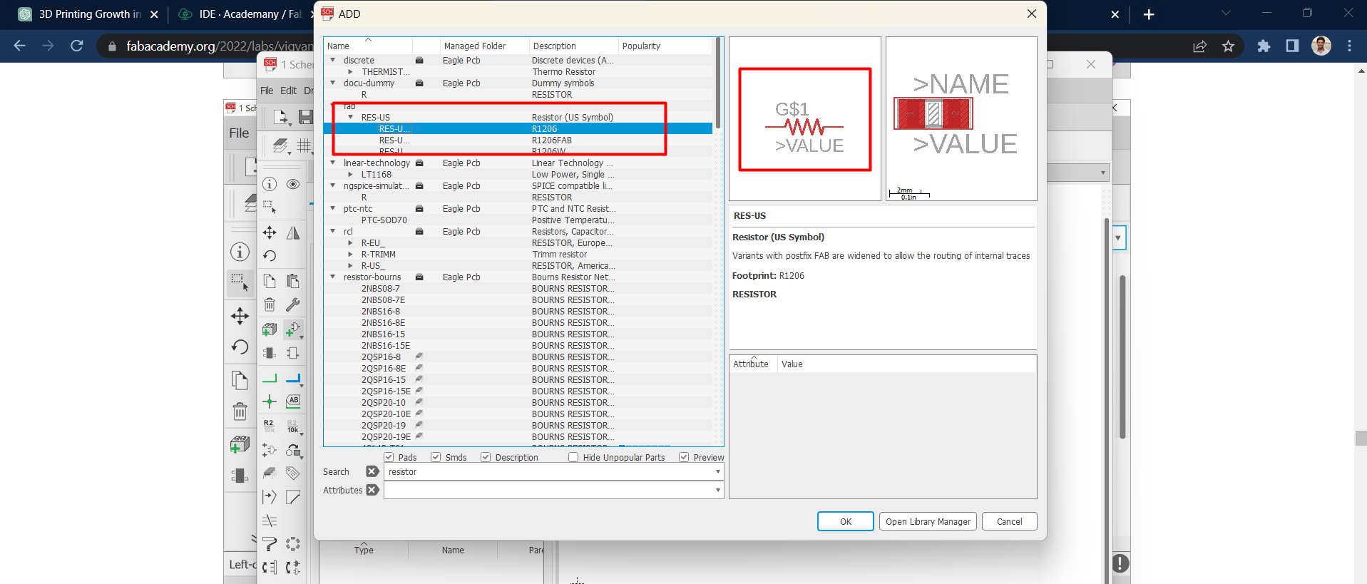
Before going forward with board designing, i wants some basic componets like resitor, led and switches as i am doing assignement for fab academy course. i have downloaded Fab libaray available on Gitub and it actually helped me a lot to find require componets easily.

Step 3
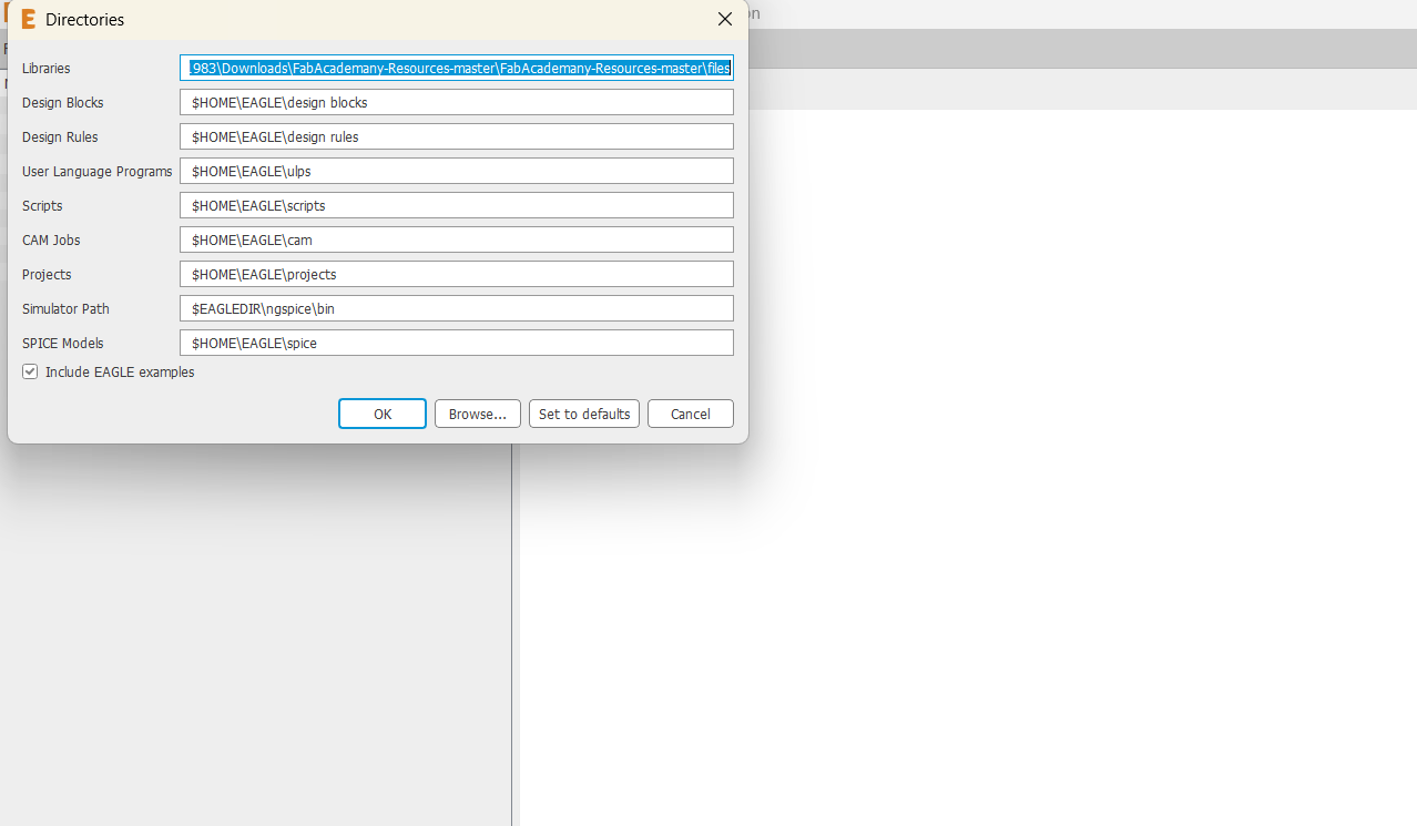
After downloading zip file of fab libaray, and by extracting it i have uploaded .lbr file of library into my eagle library manager to use that library while designing a board.
Step 4
For this particular assignment I want to use the Xiao ESP32 C3 microcontroller board so I have downloaded the required kit library from the internet and uploaded it to the eagle library just similar to the previous one.
Step 5
After completing all minor setups, I have started a new project to design a development board. Then I opened a schematic view screen to draw a path for development board.
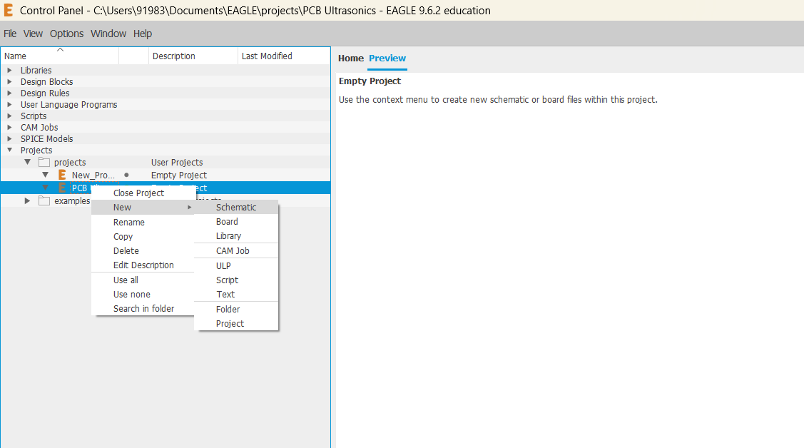
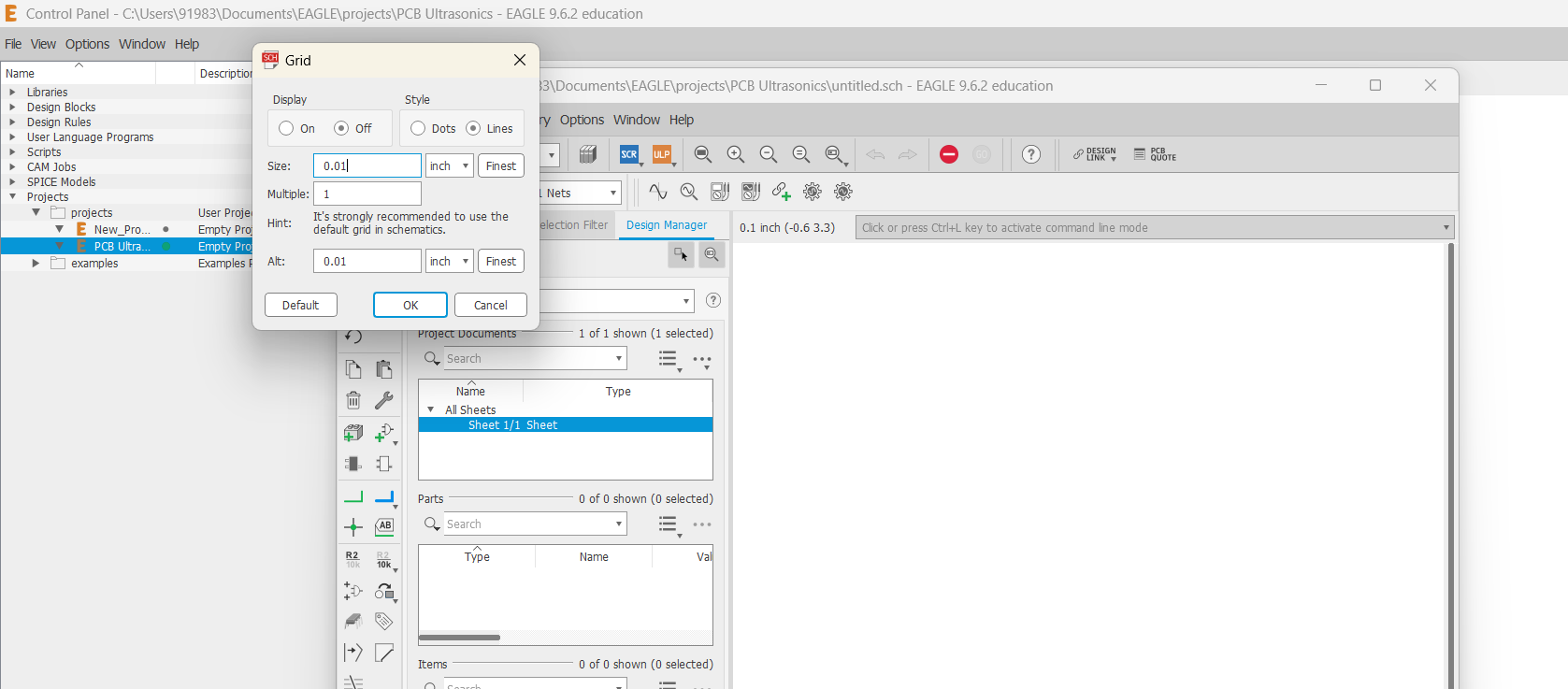
Step 6
Then I selected the value of the grid equal to 0.01 inch so we can draw and route it perfectly well.
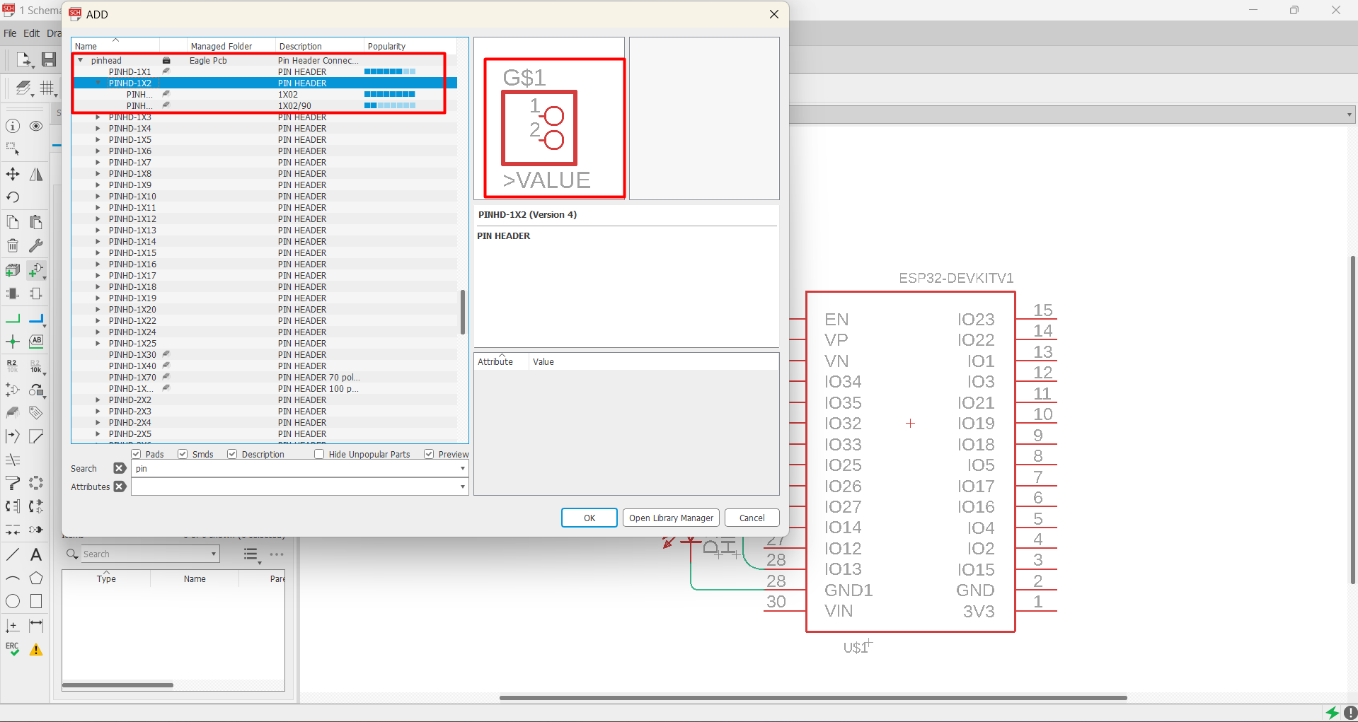
Step 7
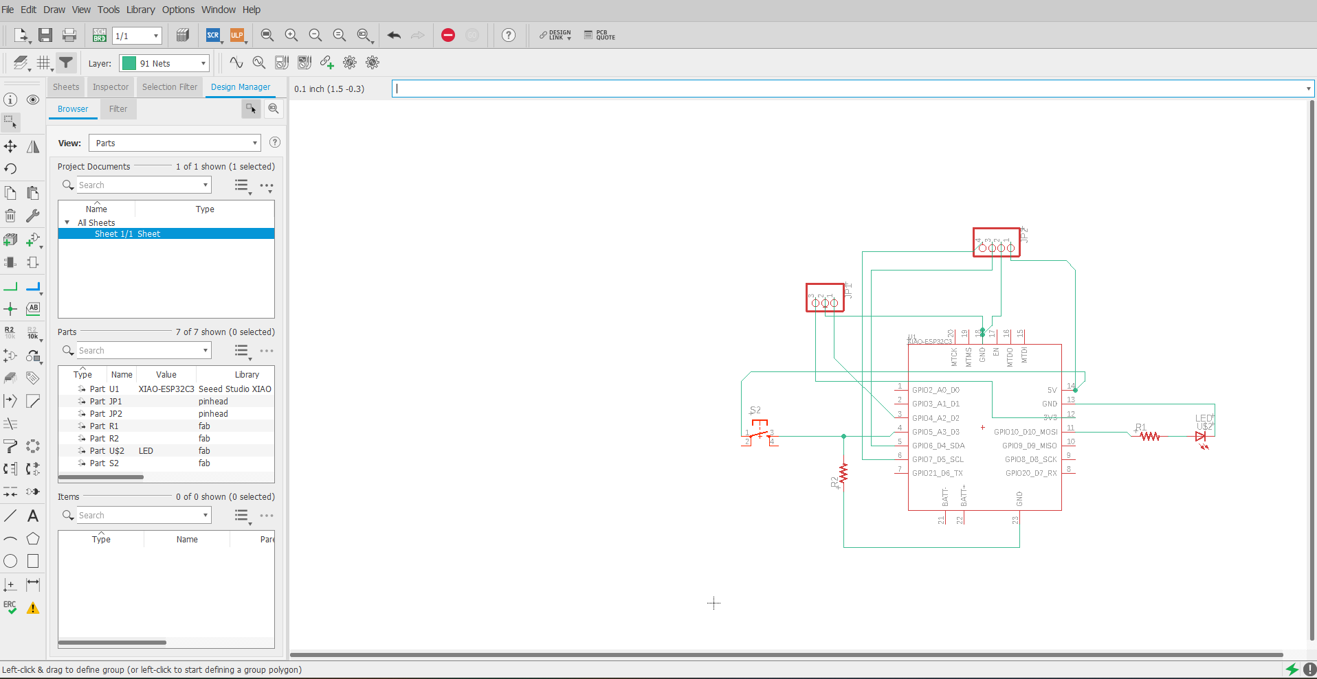
After adding the required libraries I started designing PCB by adding require components for my project like Xiao ESP32 c3 microcontroller, Led, resistor, Pinhead, etc.
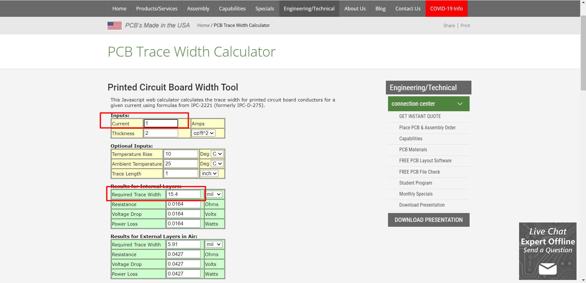
to power up 3.3 v LED with 5 v input supply we require 100 ohm resistor, and i did the calculation for the same.
Step 8
After collecting all required components for the design a microcontroller has re-arranged the position of components to each other to make PCB more compact & collect each other by using “NET” command.
Step 9
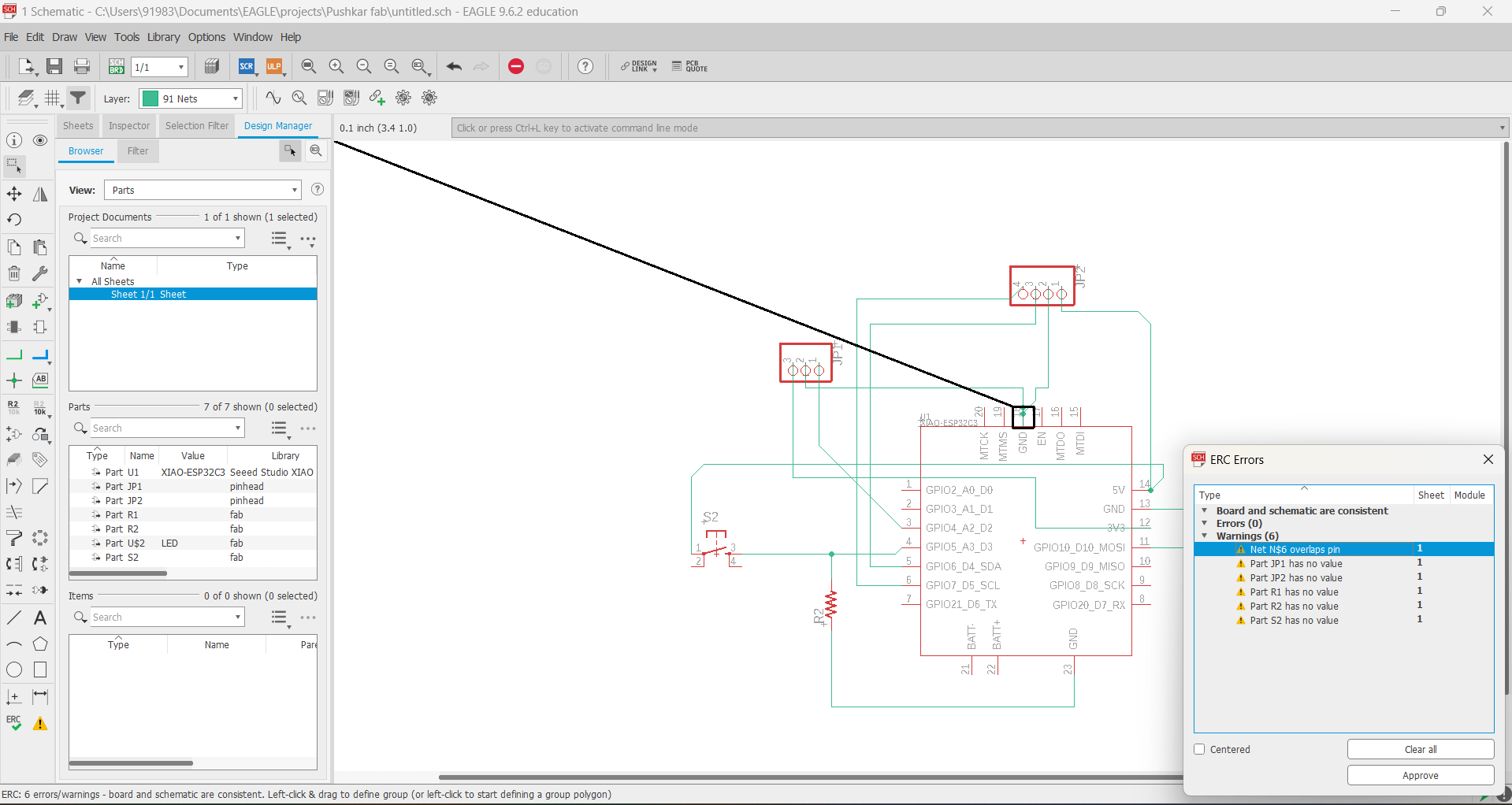
After connecting each component to the other, I did ERC check of my design to check for errors in it.
Step 10
ERC check showed some errors and warning for my board design, after revivewing all the suggested errors with my board i have stared to remove those one by one.
Step 11
After successfully completing the designing process, I generated its switchboard, where all the components gather at the bottom end of switch board along with nets.
Initially, the board looks a little bit messy as all components overlapped each other also all nets were crossing each other. So, for that initially, I move the entire design to the box and started positioning it in order to reduce its complexity.

Step 12
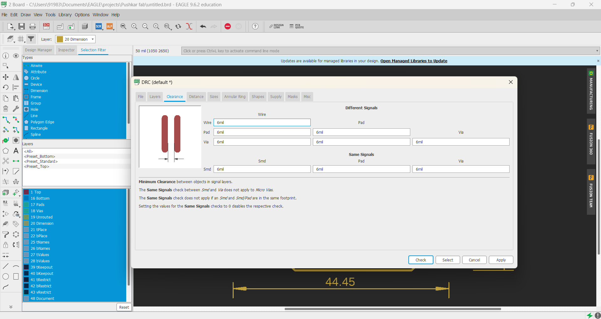
After rearranging the position of all the components, I did DRC check of my design where I set values of clearance and size after setting up all design rules.
Step 13
After checking all the design rules, I started creating traces on that design using the route air wire command. The width of the trace is very important in order to reduce failure in the future, so for, that I have calculated the trace width respective to 1 amp current and the value of width is 16 mil.
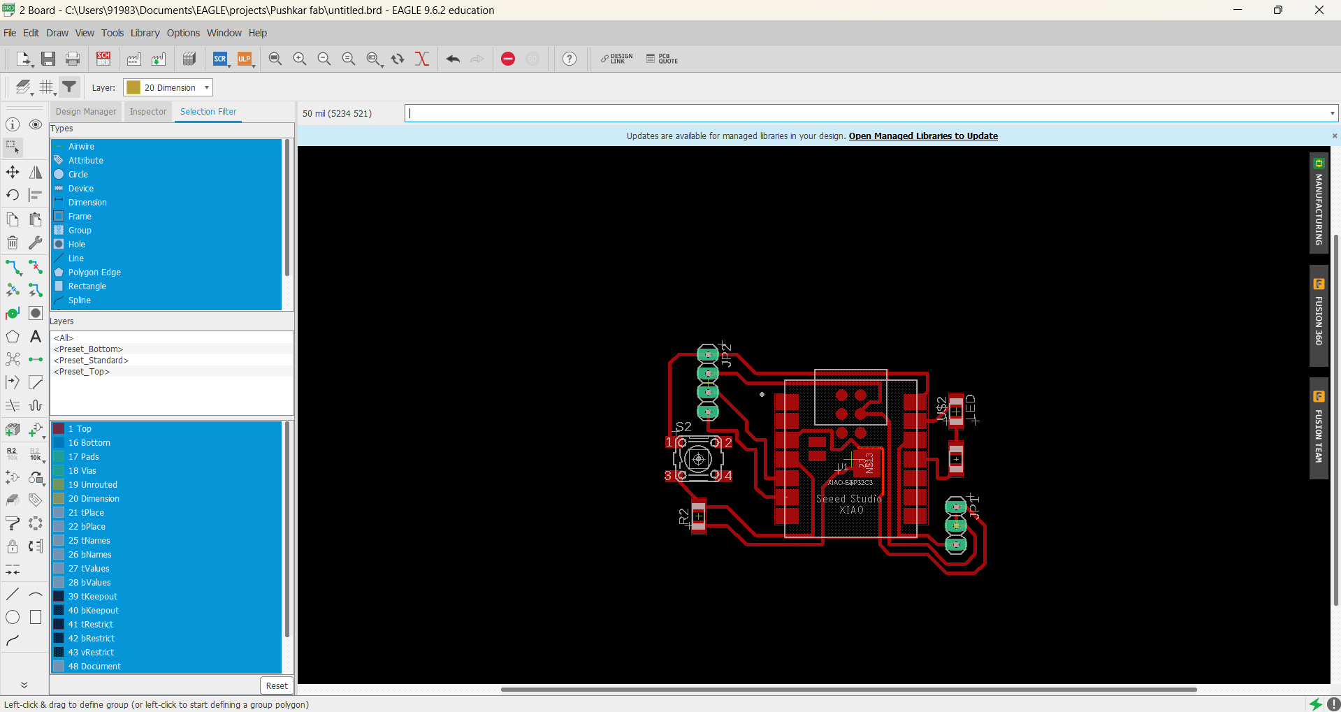
Step 14
After successfully tracing all the connections the final board is looking like this.
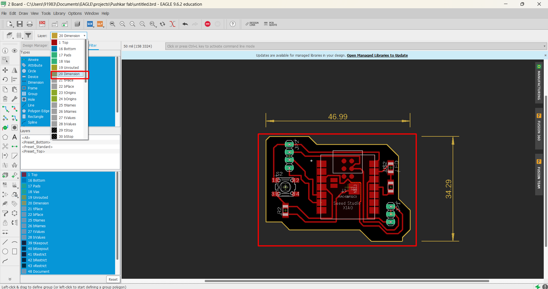
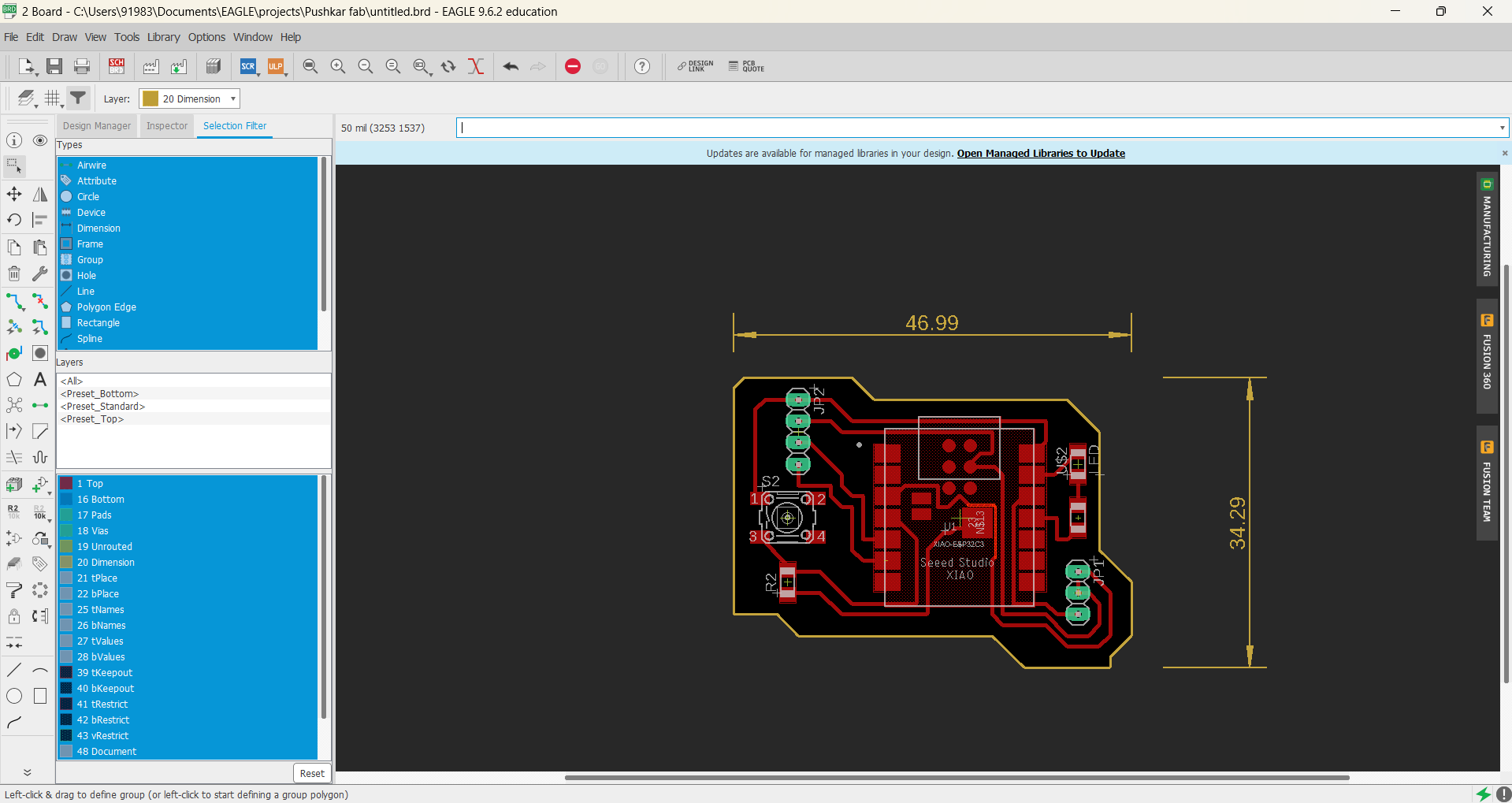
Step 15
After fixing the position of each component and tracing the path finally I draw a border by changing the value of layer dimension outside the board and also gave him dimensional values.
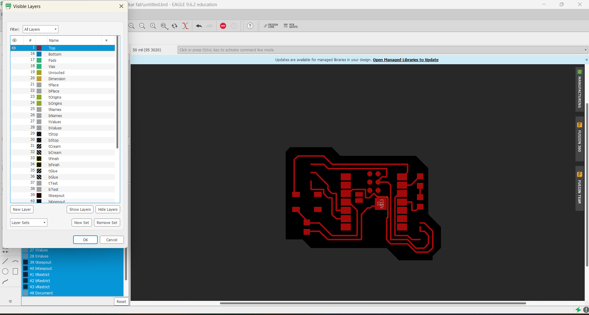
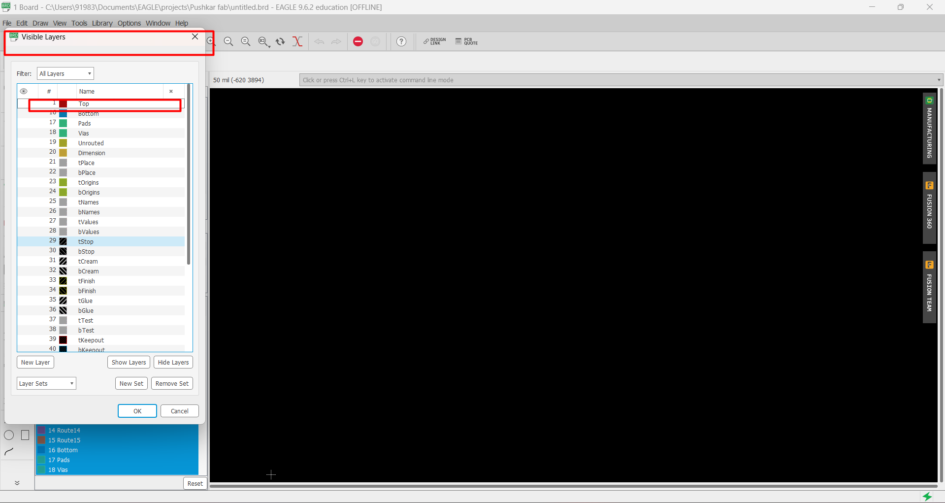
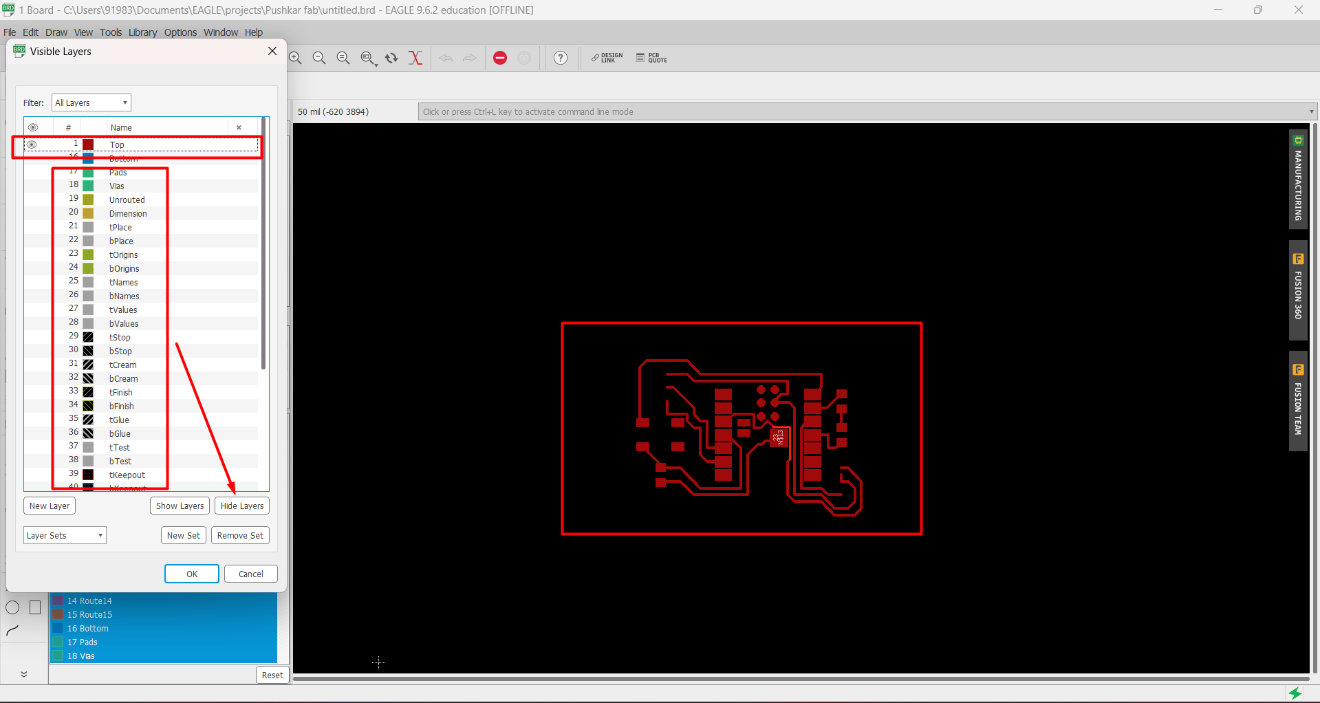
 After completing skematic and board design, we need to convert and download it into .png file format, which will be used in mods.
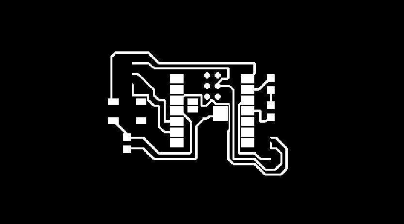
so i have hide all the layers except top layer.
Then clicked on Files> Export> Image.
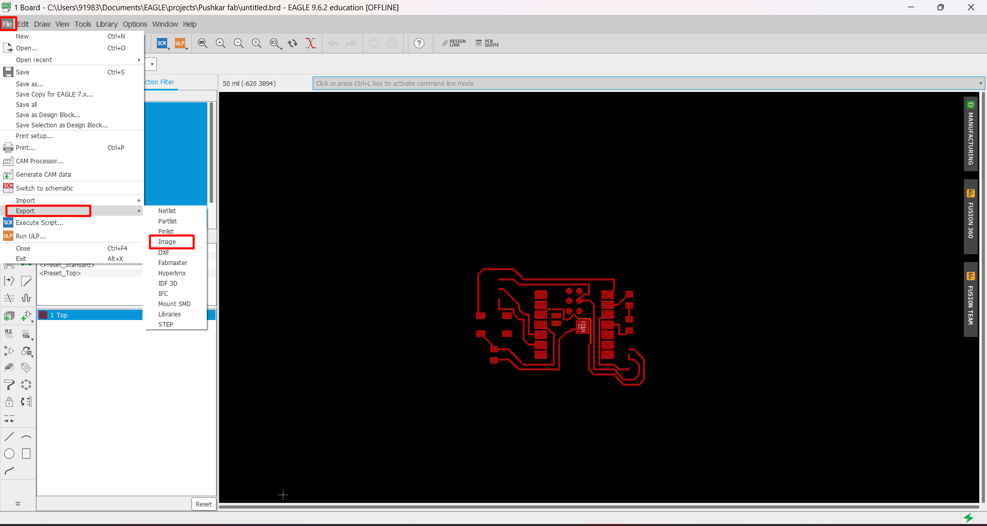
And a pop up screen is opened to put values of settings like resolution , file loaction , file name etc.
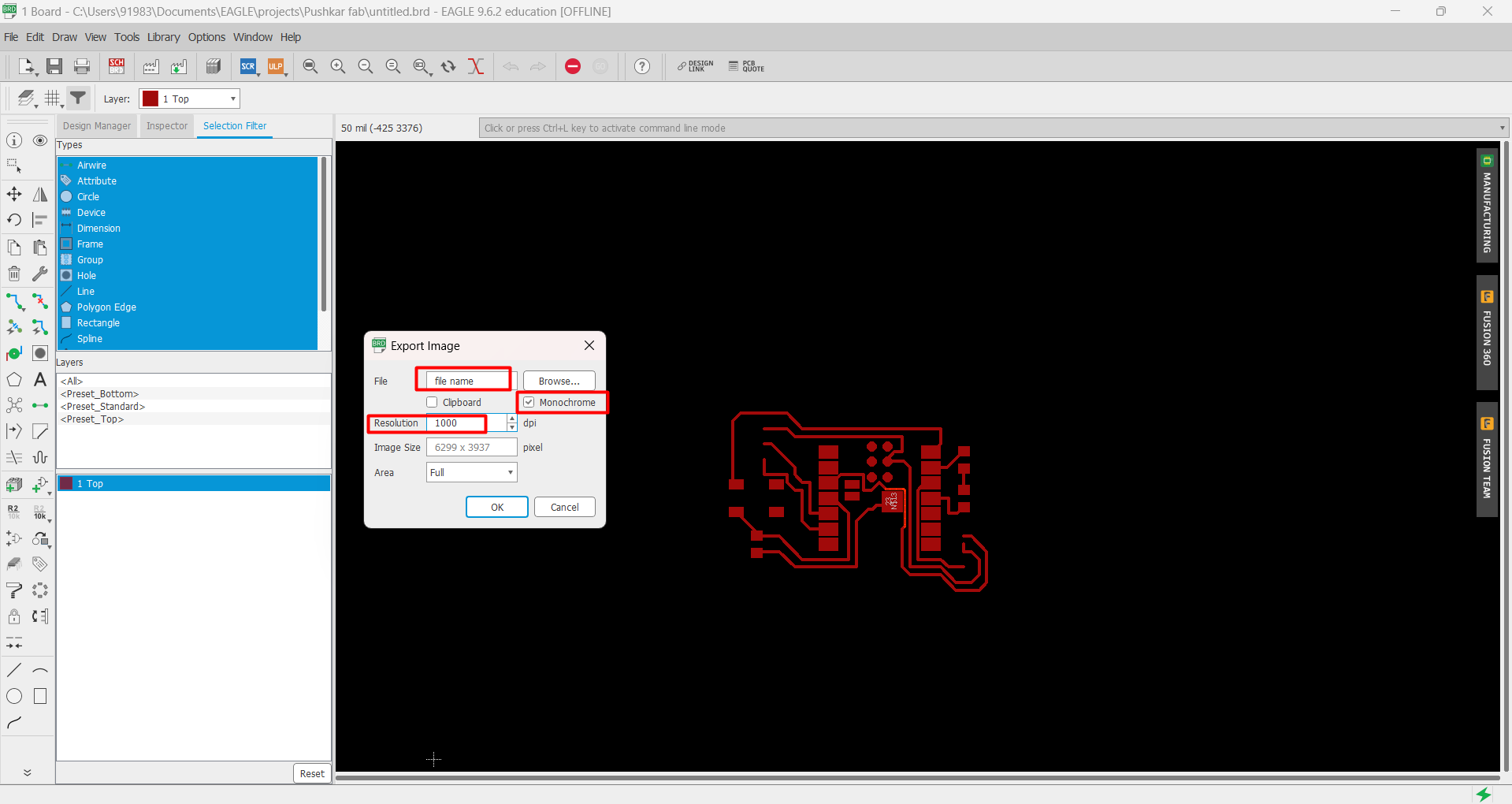
After generating .png file, it can be ready to upload on mods for further processing.
Learning from this week
1) Use different test equipments in our lab
2) Use of different Board designing software like KIcad & Autodesk Eagle
3) Add and use external libaray for board designing
4) Got aware with basic electonics
5) Become familier with basic electrnics componets
Problem Faced
1) Faced issue with finding libray fro xiao esp32 c3 board, but our instructor helped use to to find that.
2) Fcaed issue with route selection
3) Initailly my designed was very complex but my instructor helpes me to optimize that