Computer Controlled Cutting
Week 3 Assignement summary
This week I have learned Computer Controlled Cutting technology with using a Laser cutter & Vinyl cutter. I have also learned Parametric design Software along with different cam software and did different projects in our Lab using Laser and vinyl cutter machines in this report I am documenting all my learning this week.
Laser Cutting
Laser cutting is a technology that uses a laser to vaporize materials, resulting in a cut edge. While typically used for industrial manufacturing applications, it is now used by schools, small businesses, architecture, and hobbyists. Laser cutting works by directing the output of a high-power laser most commonly through optics. Laser optics and CNC (computer numerical control) are used to direct the laser beam to the material. A commercial laser for cutting materials uses a motion control system to follow a CNC or G-code of the pattern to be cut onto the material. The focused laser beam is directed at the material, which then either melts, burns vaporize away, or is blown away by a jet of gas,leaving an edge with a high-quality surface finish. (Mention Wikipedia here).
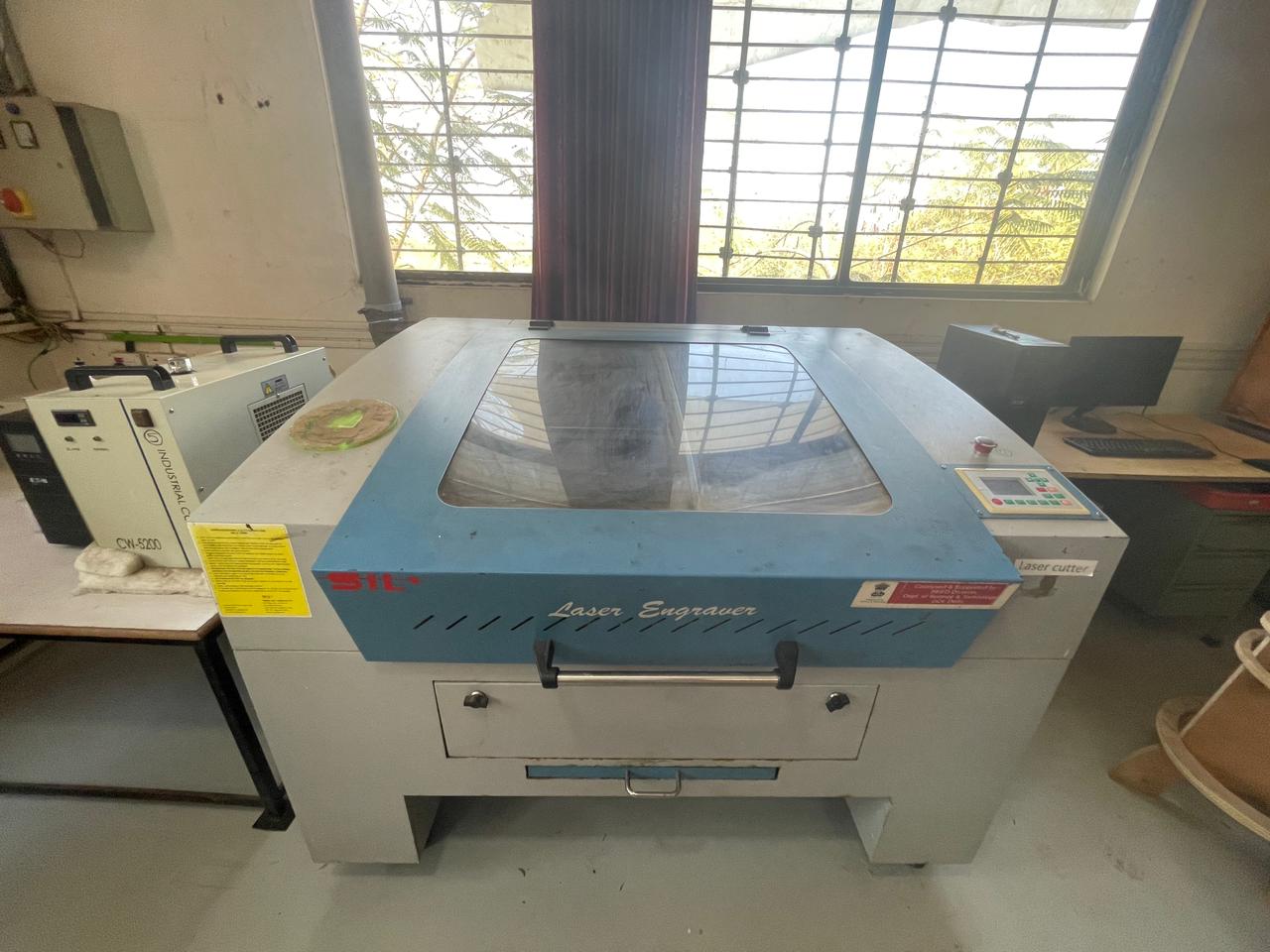
Laser Cutter @FAB LAB Vigyan Ashram
In our FAB LAB Vigyan Ashram, we have a Co2 Laser cutting machine by Suresh Indu Laser Pvt, LTD.
A vinyl cutter is an entry-level machine for making signs. Computer-designed vector files with patterns and letters are directly cut on the roll of vinyl which is mounted and fed into the vinyl cutter through a USB or serial cable. Vinyl cutters are mainly used to make signs, banners, and advertisements. Advertisements seen on automobiles and vans are often made with vinyl cut letters. While these machines were designed for cutting vinyl, they can also cut through computer and specialty papers and thicker items like thin sheets of the magnet.
In CO₂ laser cutting, laser cutting is possible with both oxygen or nitrogen. The difference is that oxygen burns the material and nitrogen melts the material. Thicker materials can be laser cut when using oxygen. The disadvantage of cutting with oxygen is that an oxide layer forms on the cutting surface. This can break off, which is not desirable if the products are preserved without pre-treatment (blasting). Nitrogen laser cutting creates a clean cutting surface without oxide film. On the other hand, when cutting with nitrogen, cutting surfaces are sometimes less smooth and slight burring may occur. The amount of spatter on the inside of the product is also greater than when cutting with oxygen.
referance taken from Wikipedia

Vinyl Cutter
A vinyl cutter is an entry-level machine for making signs. Computer-designed vector files with patterns and letters are directly cut on the roll of vinyl which is mounted and fed into the vinyl cutter through a USB or serial cable. Vinyl cutters are mainly used to make signs, banners, and advertisements. Advertisements seen on automobiles and vans are often made with vinyl cut letters. While these machines were designed for cutting vinyl, they can also cut through computer and specialty papers and thicker items like thin sheets of the magnet.
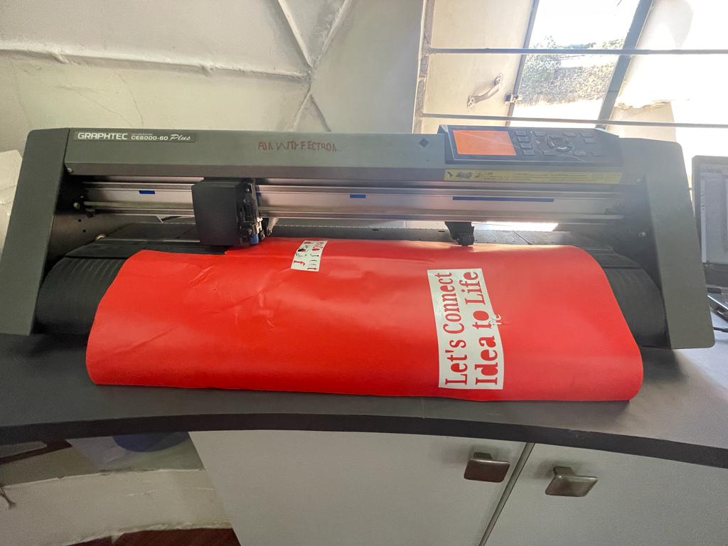
Vinyl Cutter @FAB LAB Vigyan Ashram
The GRAPHTEC CE6000 Plus Series Vinyl Cutter / Cutting Plotter is amongst the easiest to use on the market whilst yielding high quality results every time. Built-in front control panel provides complete parameter control including eight preset cutting conditions, as well as advanced features such as tangential control mode for smaller designs, down force offset, pen up speed, blade wear monitoring and more. With a 25 pin RS-232C or the High Speed USB 2.0 control interface and a large 3.7” LCD screen, managing your cutting jobs is simpler than ever!
The Graphtec CE6000 Plus Series comes standard with: floor stands (except for the 15" CE-6000-40 model comes with rear media roll rack), Cutting Master Plug-in, plus Graphtec's ARMS (Automatic Registration Mark Sensor) system.
referance from Graphtech official website

Group Assignement
This week, we worked on Laser cutting and scanning group assignments. We are a total of 2 members who conducted various trials on the laser cutting machine.
Objectives of the Group Assignment
- To Understand the Laser cutting machine along with its specifications.- To Learn safety precautions while operating the Laser Cutting Machine & to be aware with its consequences.- To find out the optimum speed and power values for different materials like cardboard & MDF sheets.- To find laser kerf for both materials.
After calculating the above values, it is very convenient for us to work with a Laser cutting machine efficiently. The values of power and speed are different for different materials, Improper values of power and speed can damage of material or product or may cause major consequences.
Cardboard and MDF Sheet Cutting and engraving.
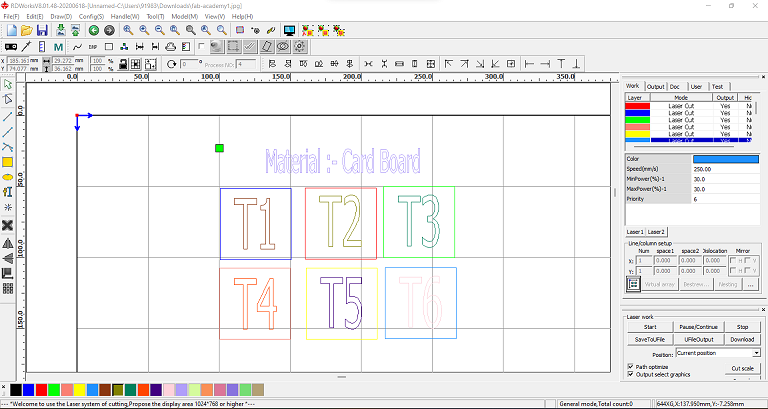
Selected a 4 mm thick cardboard and MDF sheet, and to find out the required speed and power to cut and engrave with cardboard and MDF we ran a few test cases. initially, we designed 6 rectangular shapes using RDworks cam software and set up different values and speeds for each and every rectangular box, and inserted that file into a Laser cutter. Are a few snapshots of our design work.
Results
Below are the images of the cardboard and MDF sheet used for the laser cutting operation. We have set up different values of Laser Power and speed for each test square, as shown in the images few areas got engraved properly also few test squares were also cut properly so by reviewing those results we came to one conclusion.
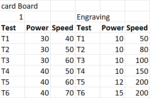
For Cardboard ideal cutting Power and speed are 40% & 50 mm/s respectively. Also for engraving on Cardboard Power and Speed is 10% & 100mm/s respectively.
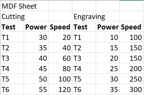
For MDF ideal cutting Power and speed are 30% & 20 mm/s respectively. Also for engraving on MDF Power and Speed are 15% & 150mm/s respectively.
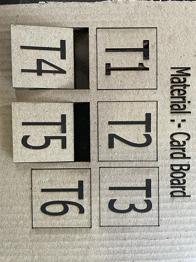
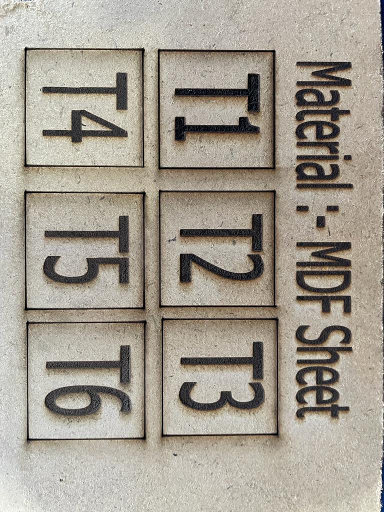
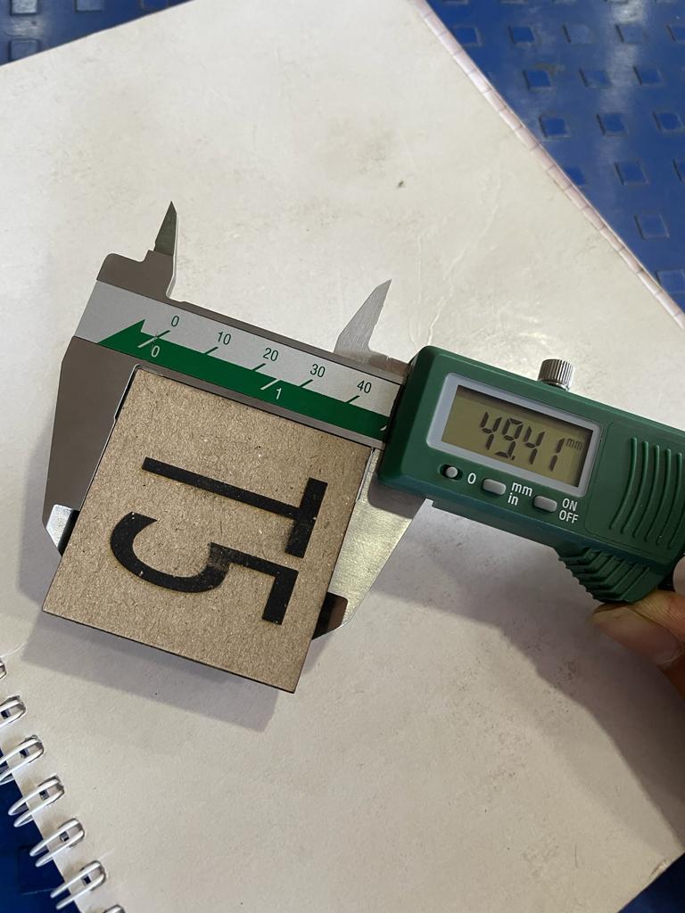
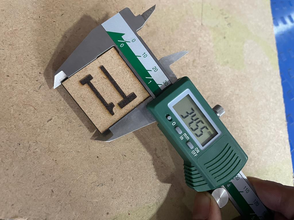
Then we calculated Kerf for 4 mm thick MDF & Cardboard. Kerf for MDF is 0.45Mm & for Cardboard, the value is 0.59mm.
Individual Assignement
Parametric Designs
Parametric design is a design method where features (such as building elements and engineering components) are shaped according to algorithmic processes, in contrast to being designed directly. This method’s parameters and rules determine the relationship between design intent and design response. The term parametric refers to input parameters fed into the algorithms.
Parametric designs are very important while designing for laser cutting, While designing for laser cutting we required multiple quantites of a perticular object. Object design contain different values of dimensions and kerf also.
so if we want to do some modification into objects dimension, parametric design can help us to minimize the work as if we change the vakue of single dimension we can see its reflection to other similar objects also.
Parametric Designs with Fusion 360
I have tried paramteric design procedure in fusion 360, as this method can reduce lots of design work. also it can help more when we need to change the shape and the size of a design.
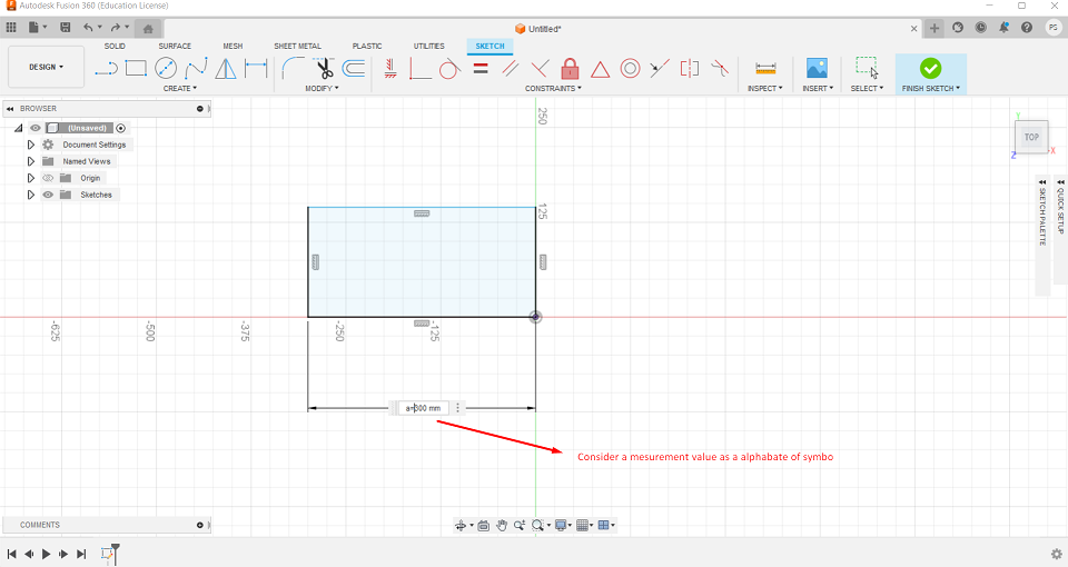
Opened fusion 360 and by selecting a plane draw a rectangle with rectangle command/tool.
Dimensions of rectangle are 300*600mm.
Then i have anoted the values with alphbates like a &b
Then by clicking on chnage parameters command under modify tool section.
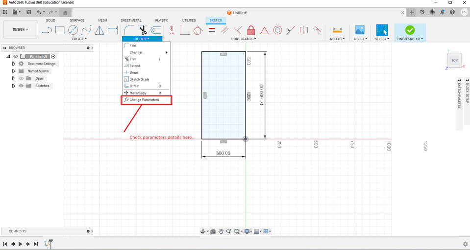
Then parameters dialog box is opened where i can add as much parameters that can be used for designing.
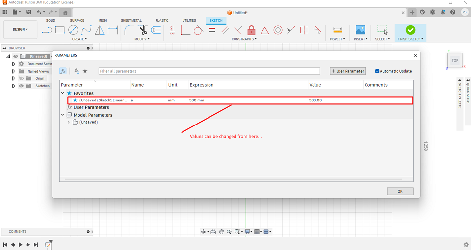
After sucessfully alloting values of parameteric alphabets, now i can put dimensions in the form of alphabets and then that much valued dimensions will occure their.
Construction kit using parametric modelling in fusion 360
for construction kit using pressfit joint, i wanted to design a geometry that can be assembled in multiple way, so i have tried to design this geometry.
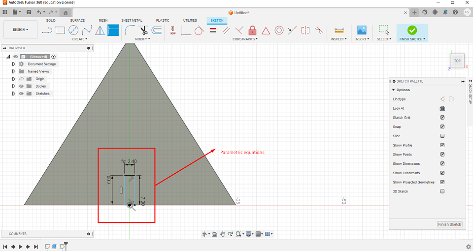
Initially by using line command i have drawn traingular geometry and set different parameters for differnt dimensions e.g. t for thickness 3mm, a for height 5 mm & k for kerf 0.15 mm etc.
initially i have set-up values for A dimension, material thickness and the kerf that o have calculated in paramteric design.
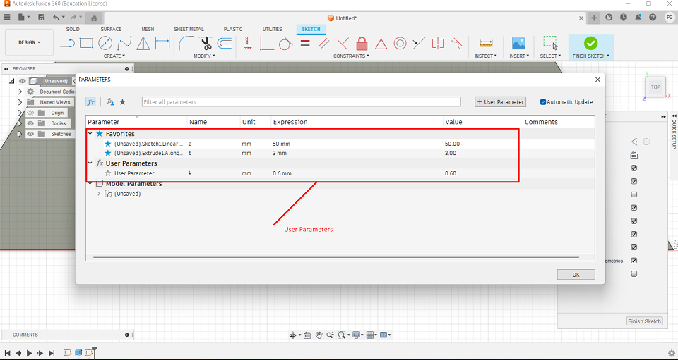
To make a slot into it i have used paramteric design fuction i.e (t-k).
Did the same procedure for the rest of other 2 sides also, to make slots from those sides also.
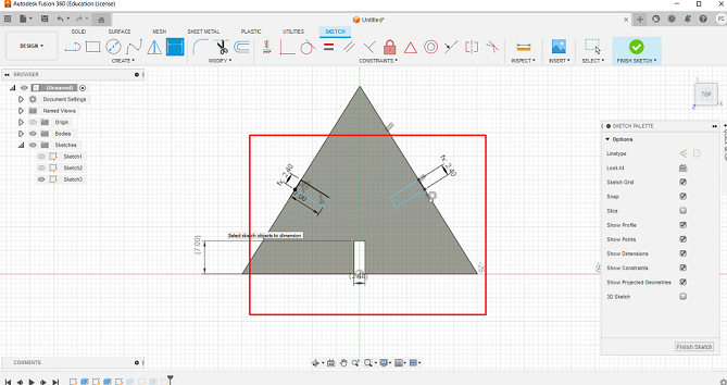
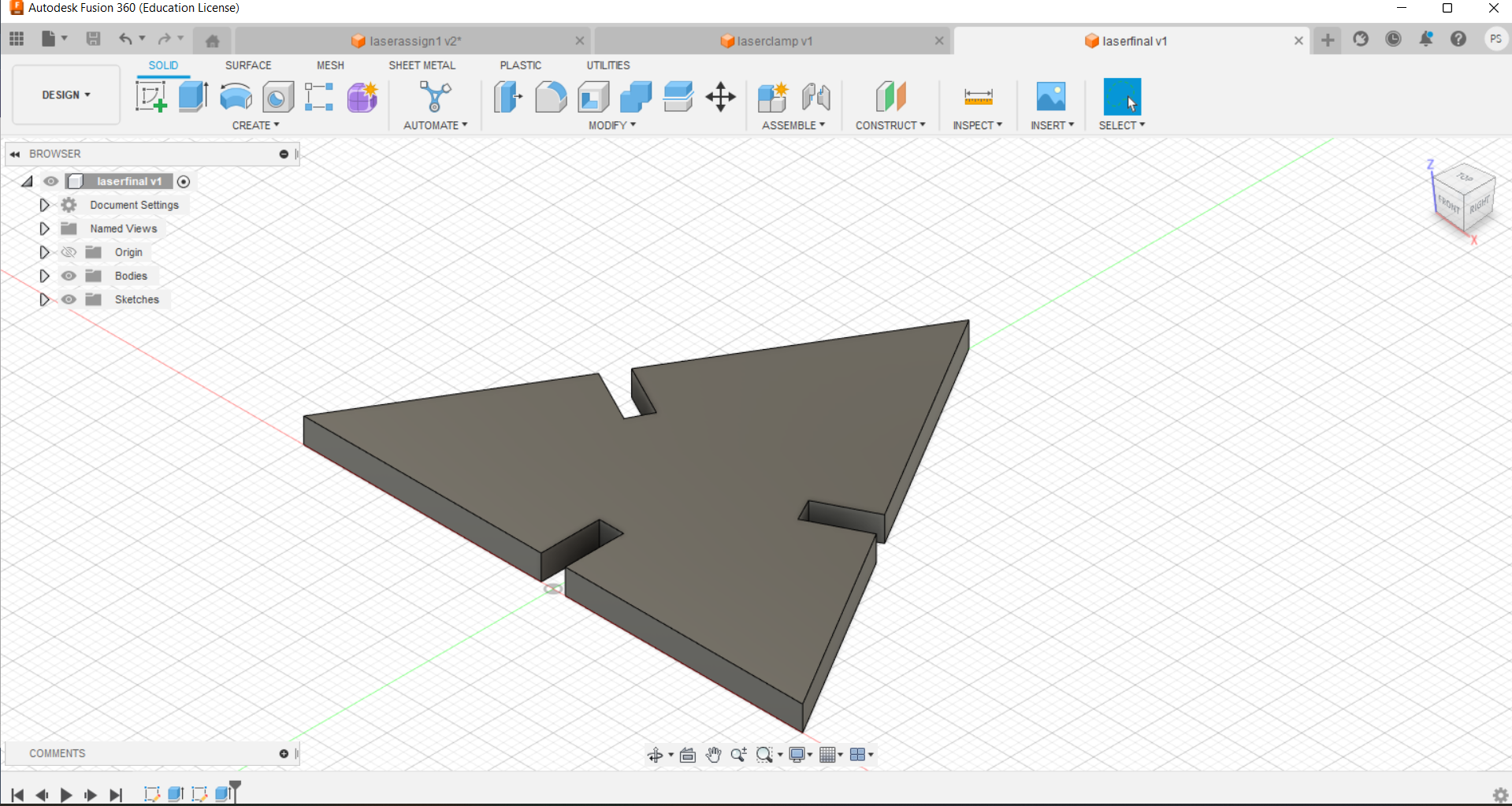
After completion of basic sketch, i extruded the design and this is the final design that i have got.
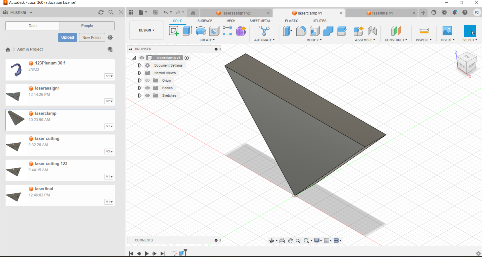
To joint two traingular MDF parts, i have design a traingular shape to lock or join two or more such kind of geometries inorder to get desire output.
After completion of design process and export that design into .dxf file format
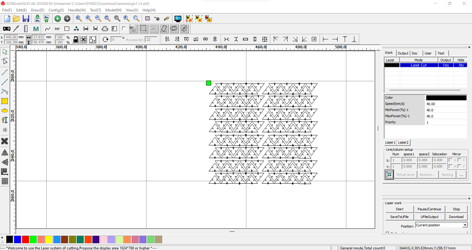
RDworks Software
RDworks Software to communicate and trasfer file to the laser cutter,Inserted values of power and speed for MDF material. i did set up build platform and the origine and started cutting.
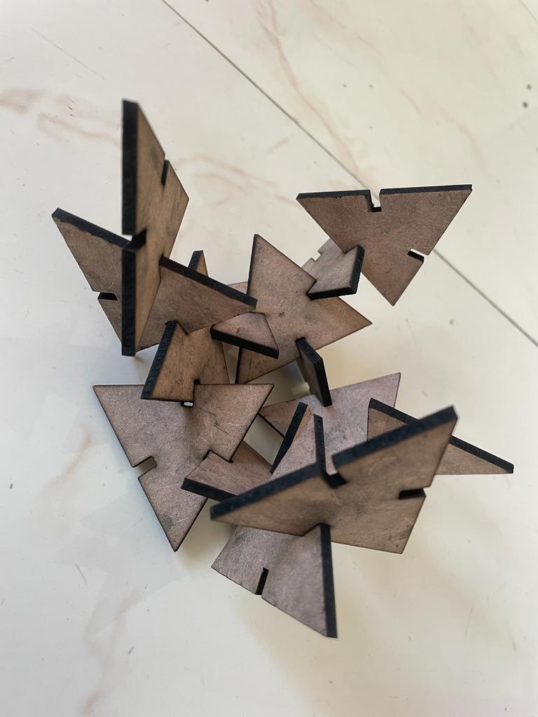
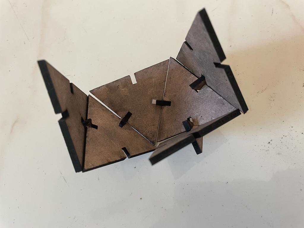
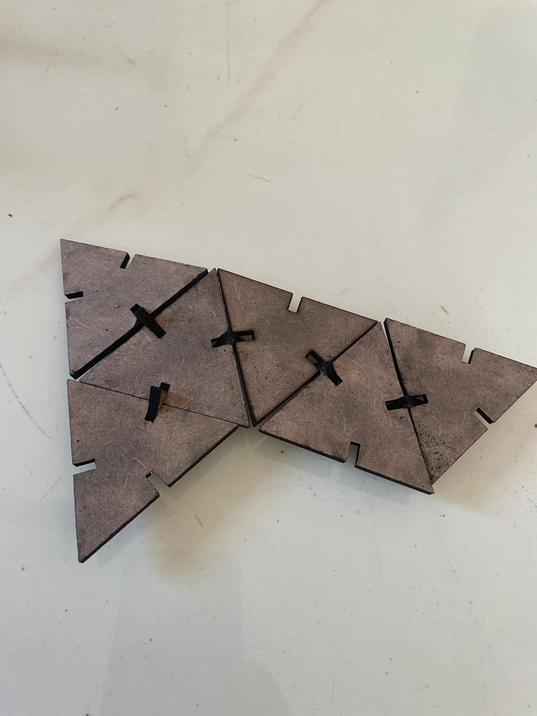
Different assembly after Cutting Process
Vinyl Cutter
A vinyl cutter is an entry-level machine for making signs. Computer-designed vector files with patterns and letters are directly cut on the roll of vinyl which is mounted and fed into the vinyl cutter through a USB or serial cable. Vinyl cutters are mainly used to make signs, banners, and advertisements. Advertisements seen on automobiles and vans are often made with vinyl cut letters. While these machines were designed for cutting vinyl, they can also cut through computer and specialty papers, as well as thicker items like thin sheets of the magnet.
The GRAPHTEC CE6000 Plus Series Vinyl Cutter / Cutting Plotter is amongst the easiest to use on the market whilst yielding high quality results every time. Built-in front control panel provides complete parameter control including eight preset cutting conditions, as well as advanced features such as tangential control mode for smaller designs, down force offset, pen up speed, blade wear monitoring and more. With a 25 pin RS-232C or the High Speed USB 2.0 control interface and a large 3.7” LCD screen, managing your cutting jobs is simpler than ever!
The Graphtec CE6000 Plus Series comes standard with: floor stands (except for the 15" CE-6000-40 model comes with rear media roll rack), Cutting Master Plug-in, plus Graphtec's ARMS (Automatic Registration Mark Sensor) system.
referance from Graphtec official Website
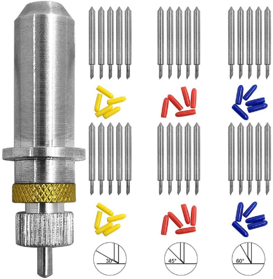
Different Types of Vinyl Cutter Blades and their types. 1) 30 deg blade is used for very thin material. 2) 45 deg blade is used for the general vinyl cutter. 3) 60 deg blade is suited for a thick material like a copper sheet, mirror sheet, or sandblast registry sheet.
Steps to operate the vinyl cutter
1) Create a design like logos or circuits using any design software. 2) Design must contain a vector in form of a line, not an infill. 3) Export that design into .png or .svg format.
Design Creation
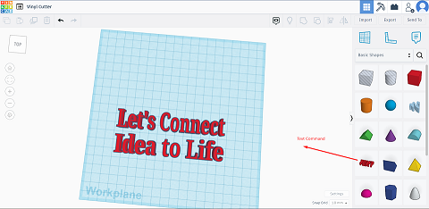
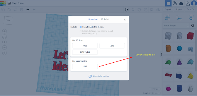
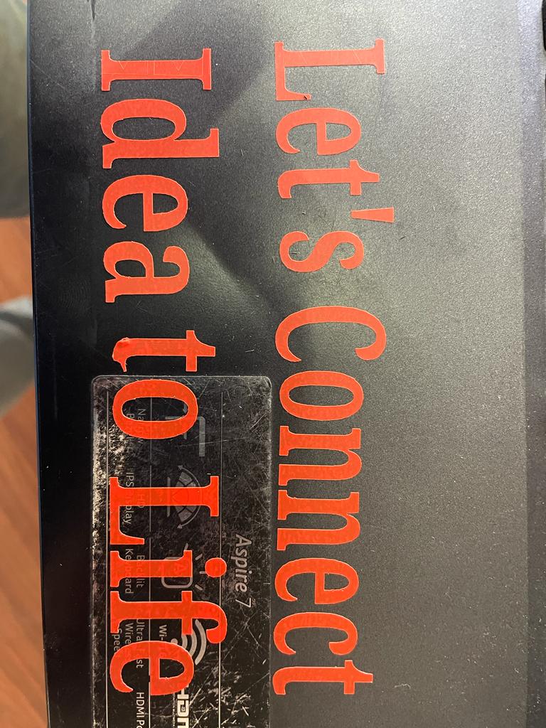
I used Tinkercad 3D modeling software for designing, using tinkercad I modified a text to a slogan.TinkerCAD Provides the option to export our design to .svg format which can be used for cutting operations.
Cam Software & cutting
Converted .svg file to .dxf file format
Installed recommanded vinyl cutter driver to local computer system
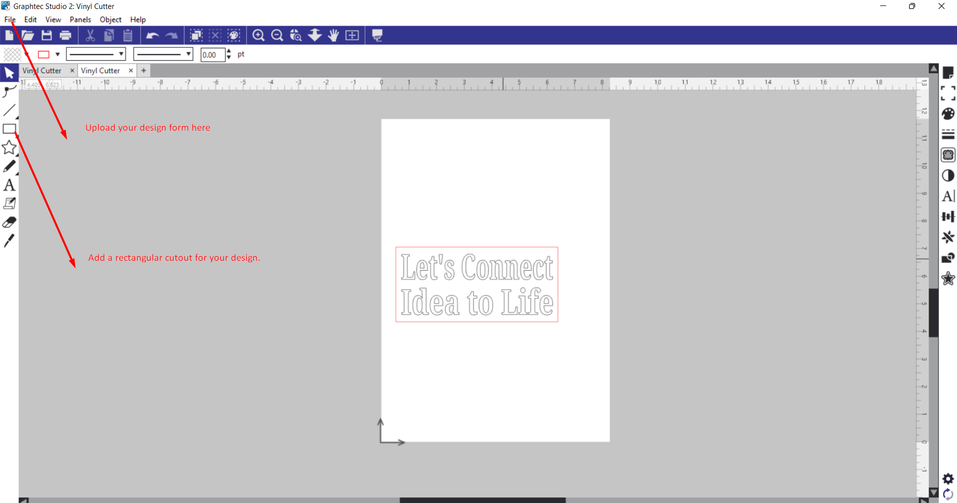
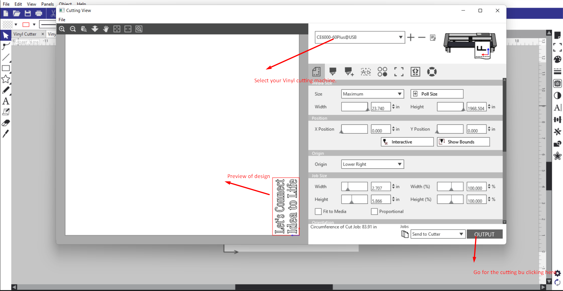
installed Graphtech studio 2 cam software for preparing design for vinyl cutting, then by uploading file into it did some modification with the scale and also use rectangular shape to insure cutout boarder for the design.
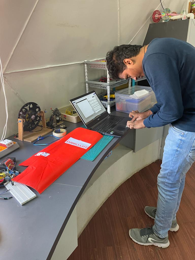
Load the vinyl paper into cutting machine, also set up origin, depth and angle of cutter as per our requirement.
for this oepartion i have used 45 deg blade angle, force 130 gf & cuuting speed 5 cm/s.
select you vinyl cutting machine before going for cutting opeartion. preview your design and then click on the outout button.
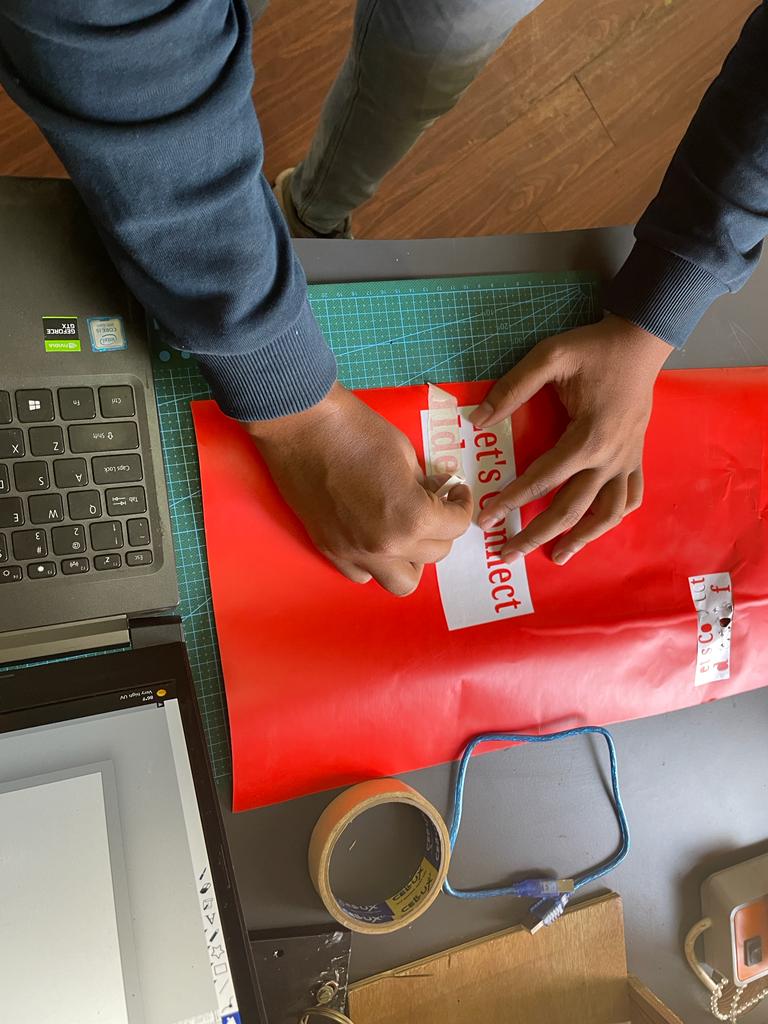
Removed design form vinyl cutting paper using paper tape.
Printed sticker is placed in the panel of my personal laptop, and it looks fantastic.
Learning of the week
What went well
Laser cutting went well. able to learn laser cutter operation and also understood how to calculate kurf and its role in press fit joints.
Able to use RD works and graphtech 2 cam softwares for laser cutting and vinyl cutter operation respectively.
What went worng
Inserted uneven vinyl papaer into vinyl cutter and faced failure.
Our Laser cutting machine requires mirror file of original file cutting, and i forget it alomst every time and faced failures.