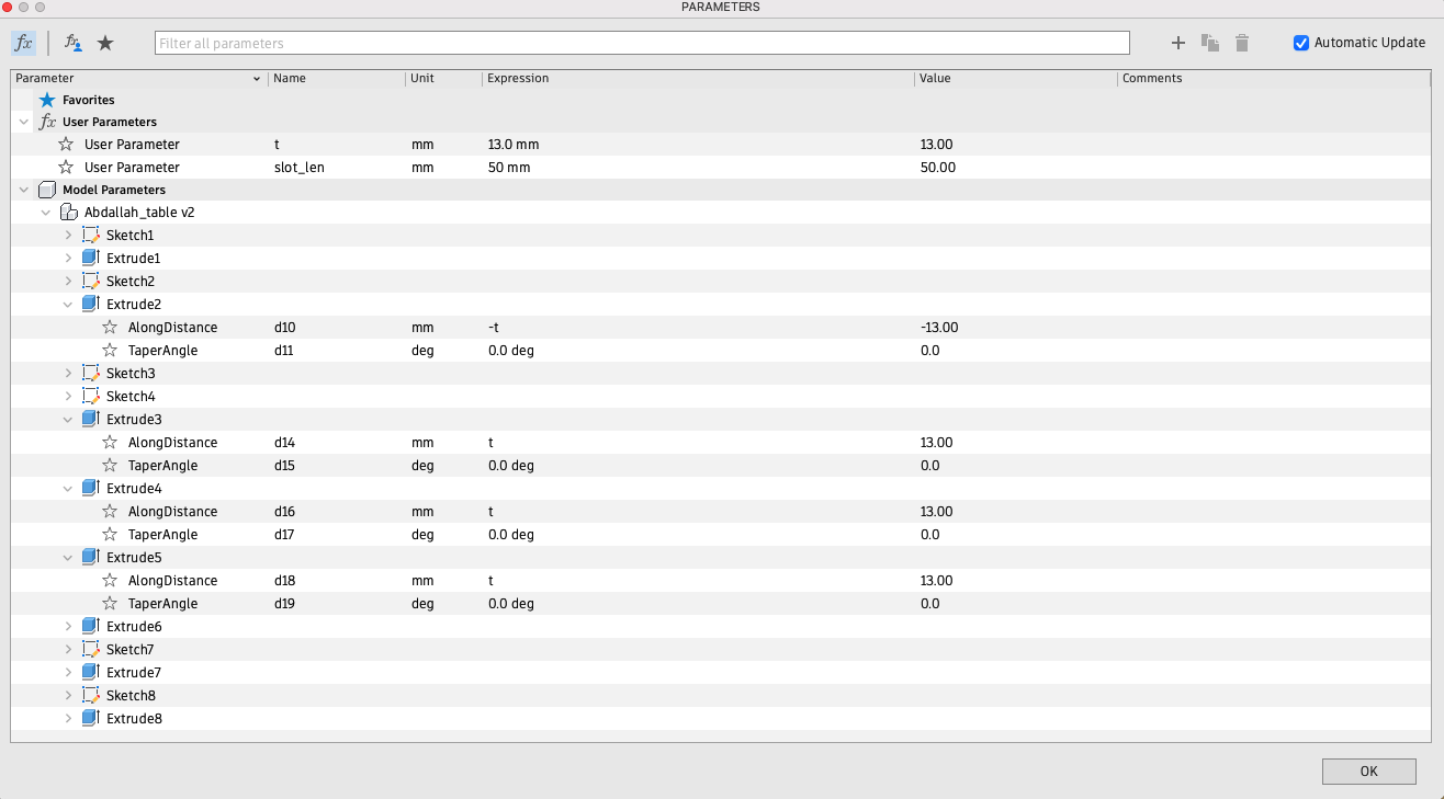
Slot_length = 50mm
t = thickness = 13.00 mm
Kerf= 0.2 mm
Documented how you designed your object (something big)
Documented how you made your CAM-toolpath
Described problems and how you fixed them
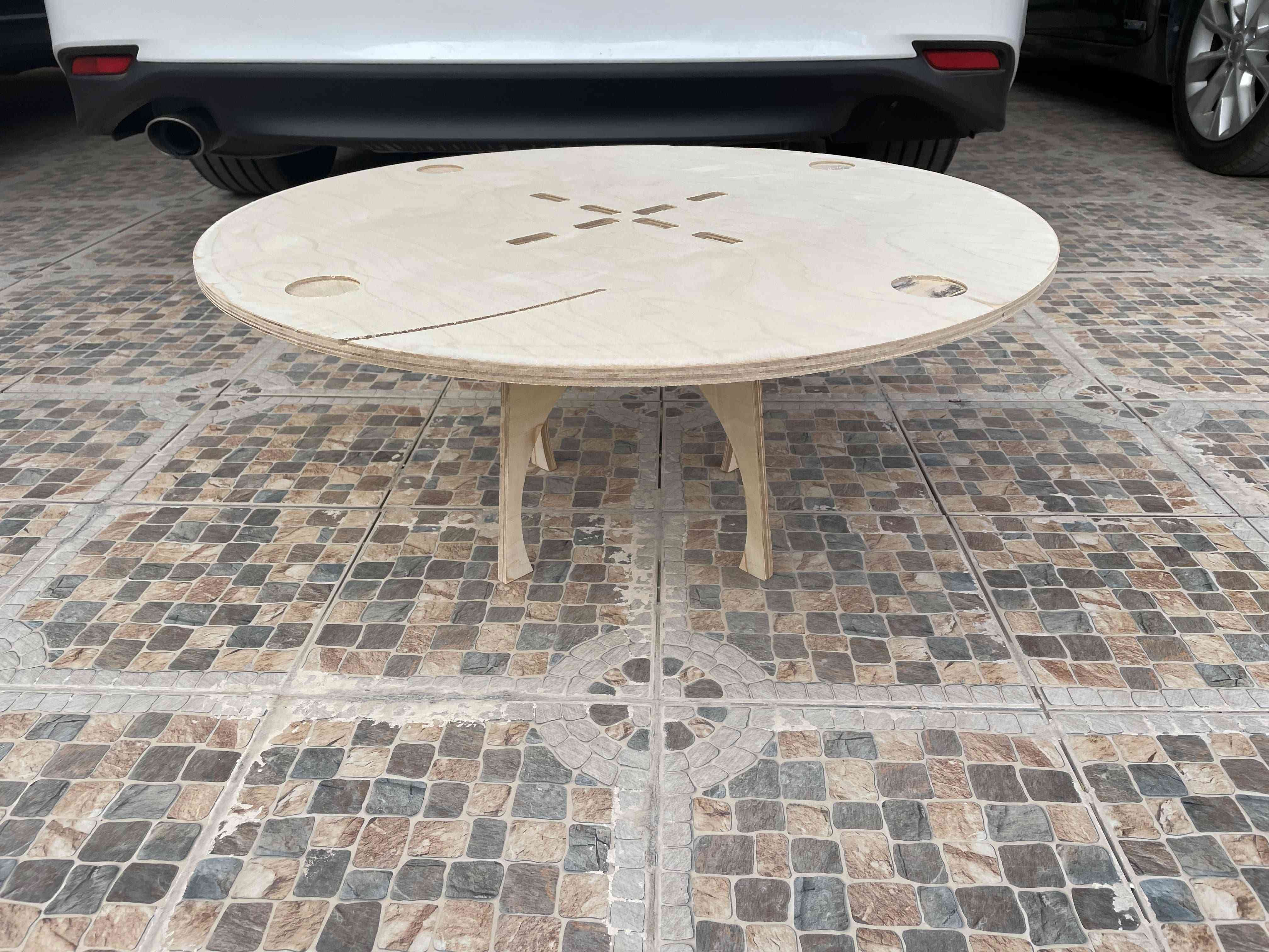
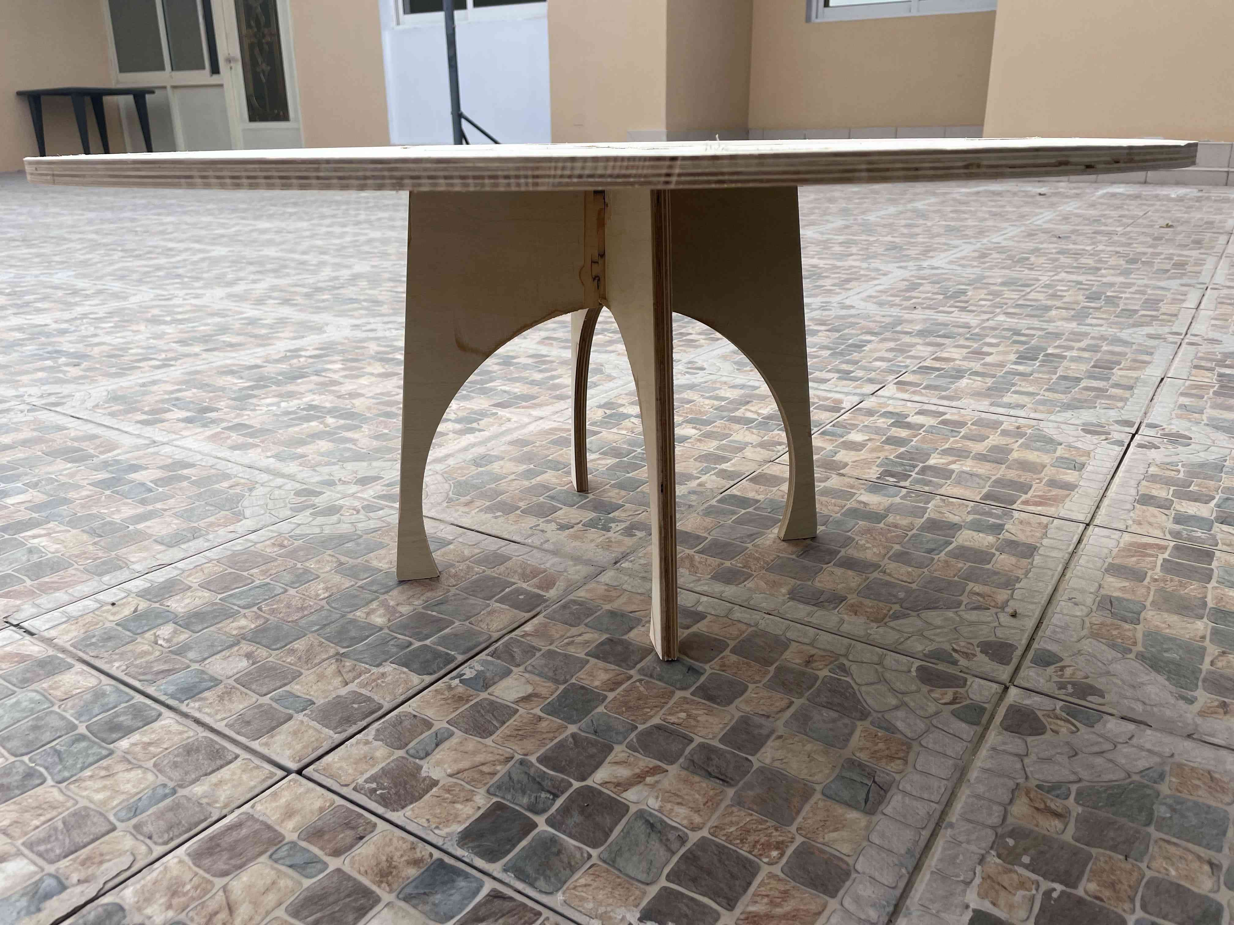
Included your design files and ‘hero shot’ photos of final object
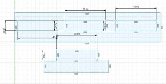
I used Fusion 360 for the designing. When the 3D model is finished, I created sketch on the surface , and project the 2D face of the wanted body to mill it. Afterward I saved it as a DXF file.
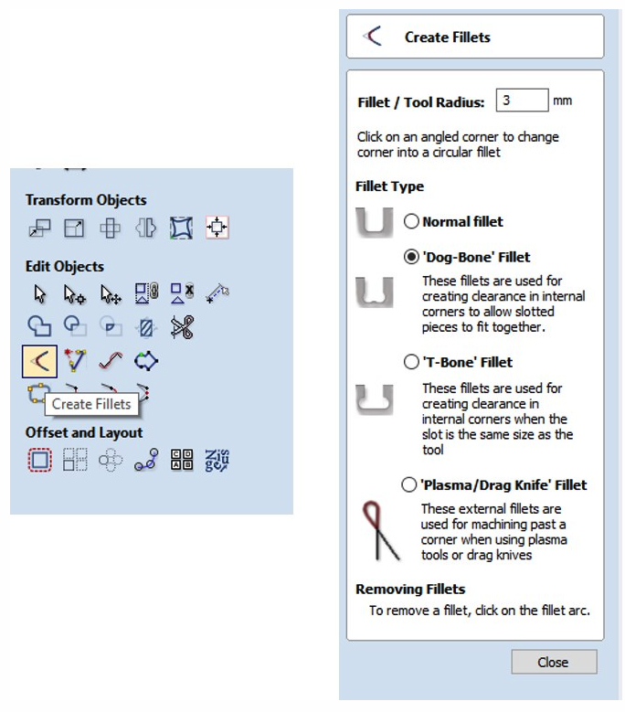
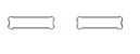
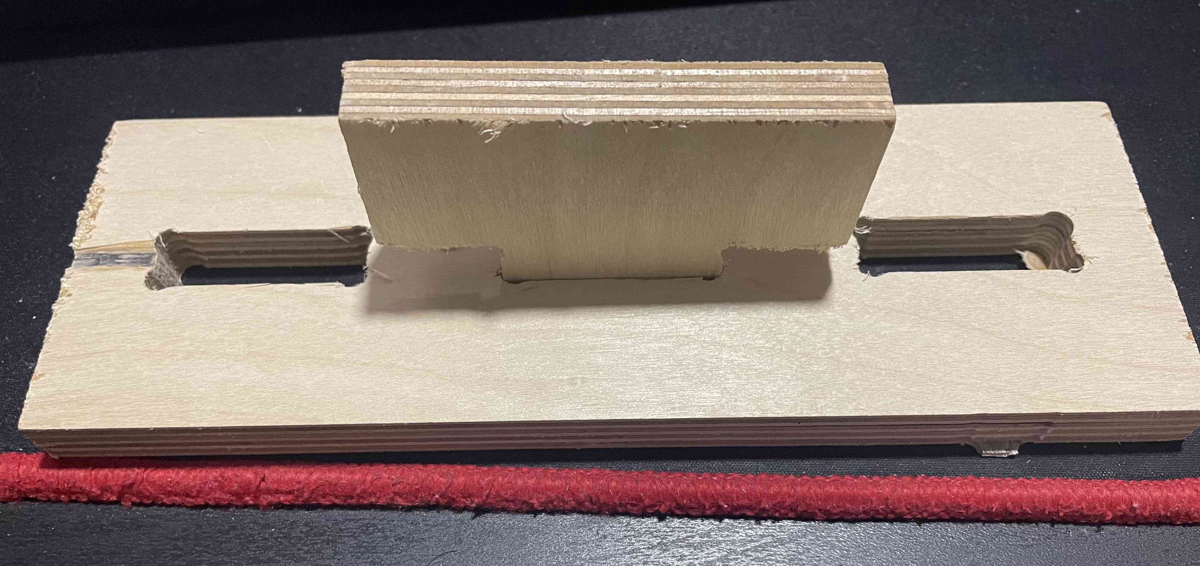
Joint and Slots:
Slot_length = 50mm
t = thickness = 13.00 mm
Kerf= 0.2 mm
I started milling using the joint test my colleagues has done before me, so I skipped the test. It was known if I will use a wood sheet with 12 mm thickness the kerf = 0.2 mm. I edited my design according to this value.
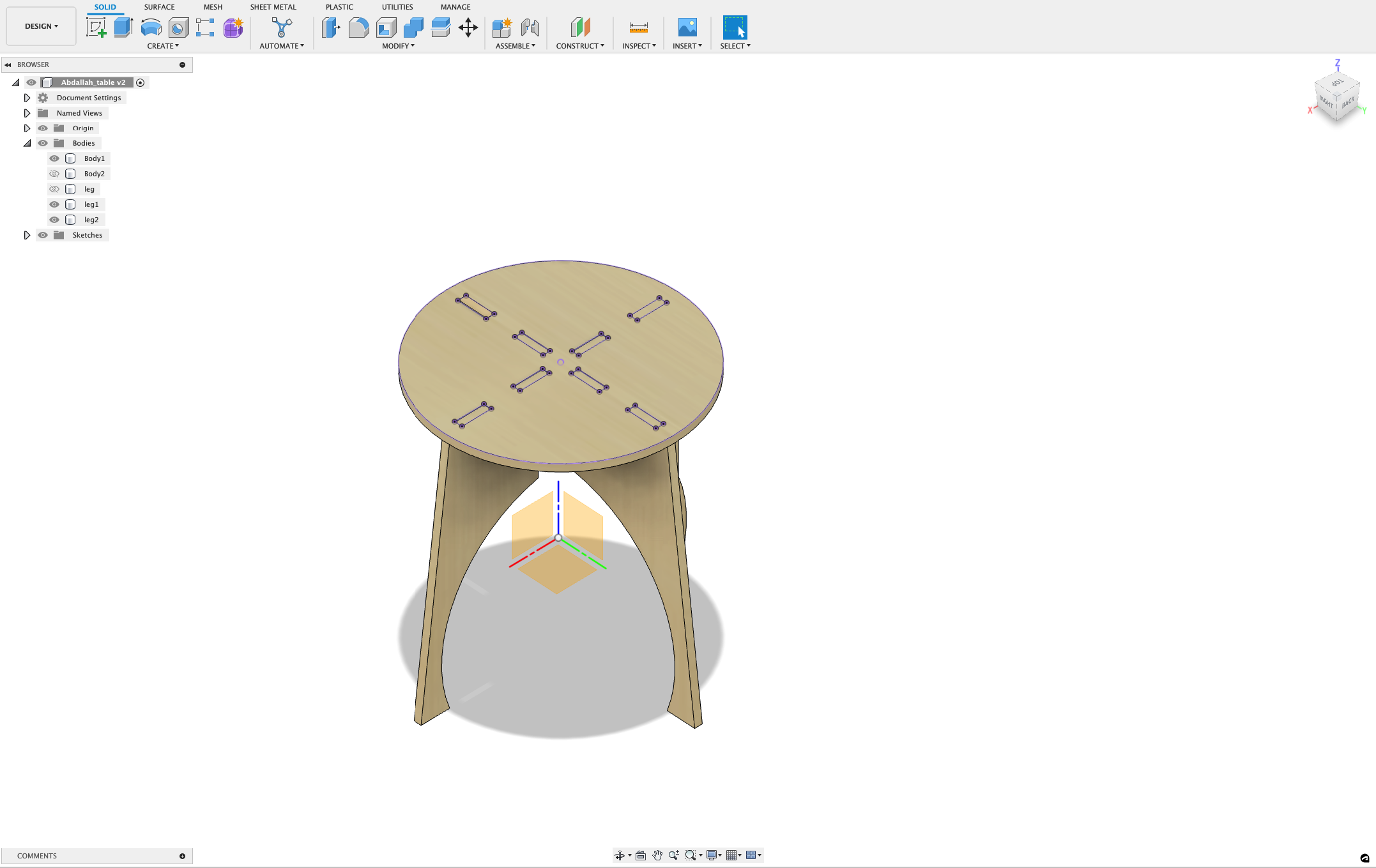
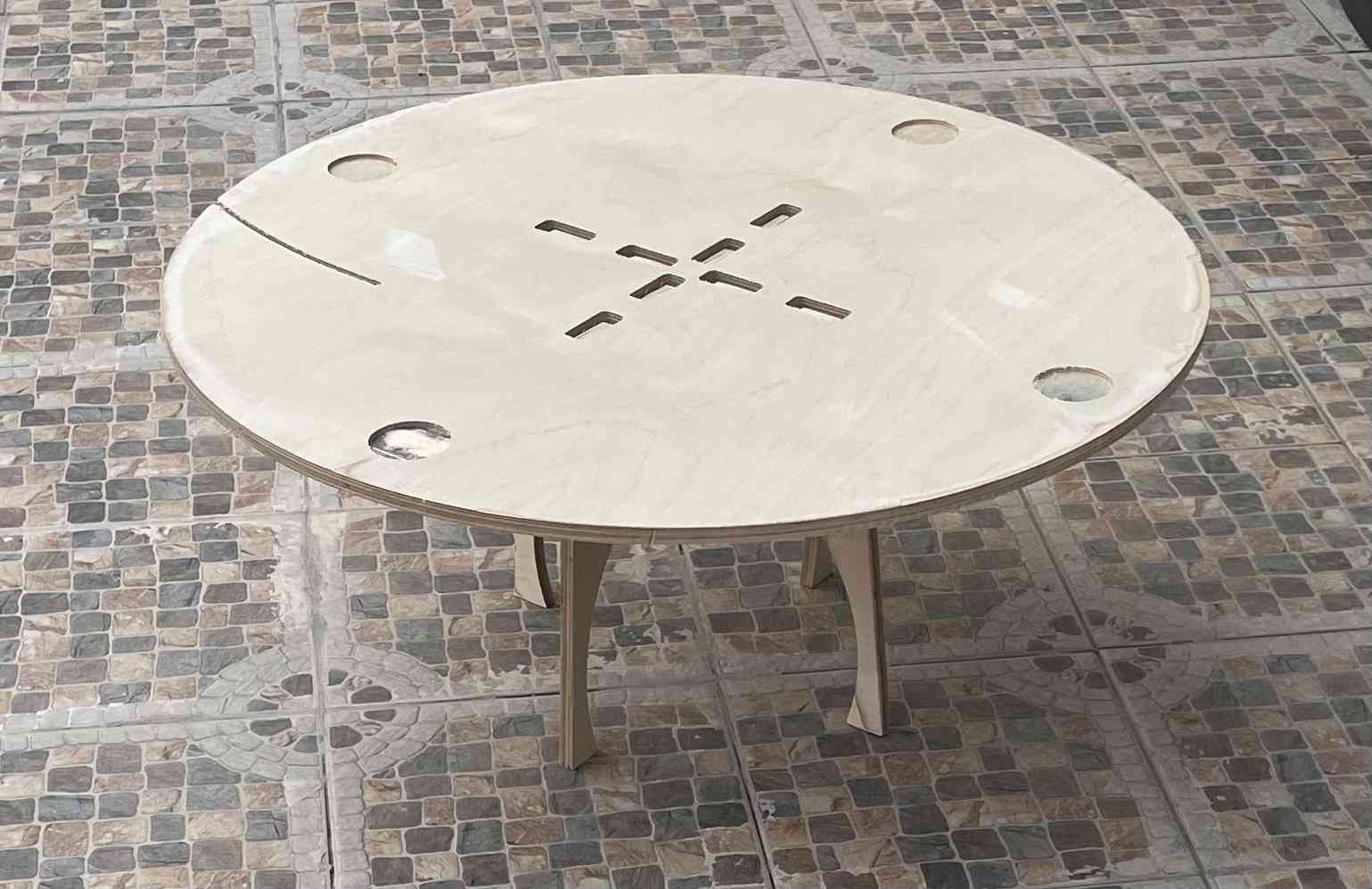
As shown above, in the 3D model of the table and how the leg connected to the table top.
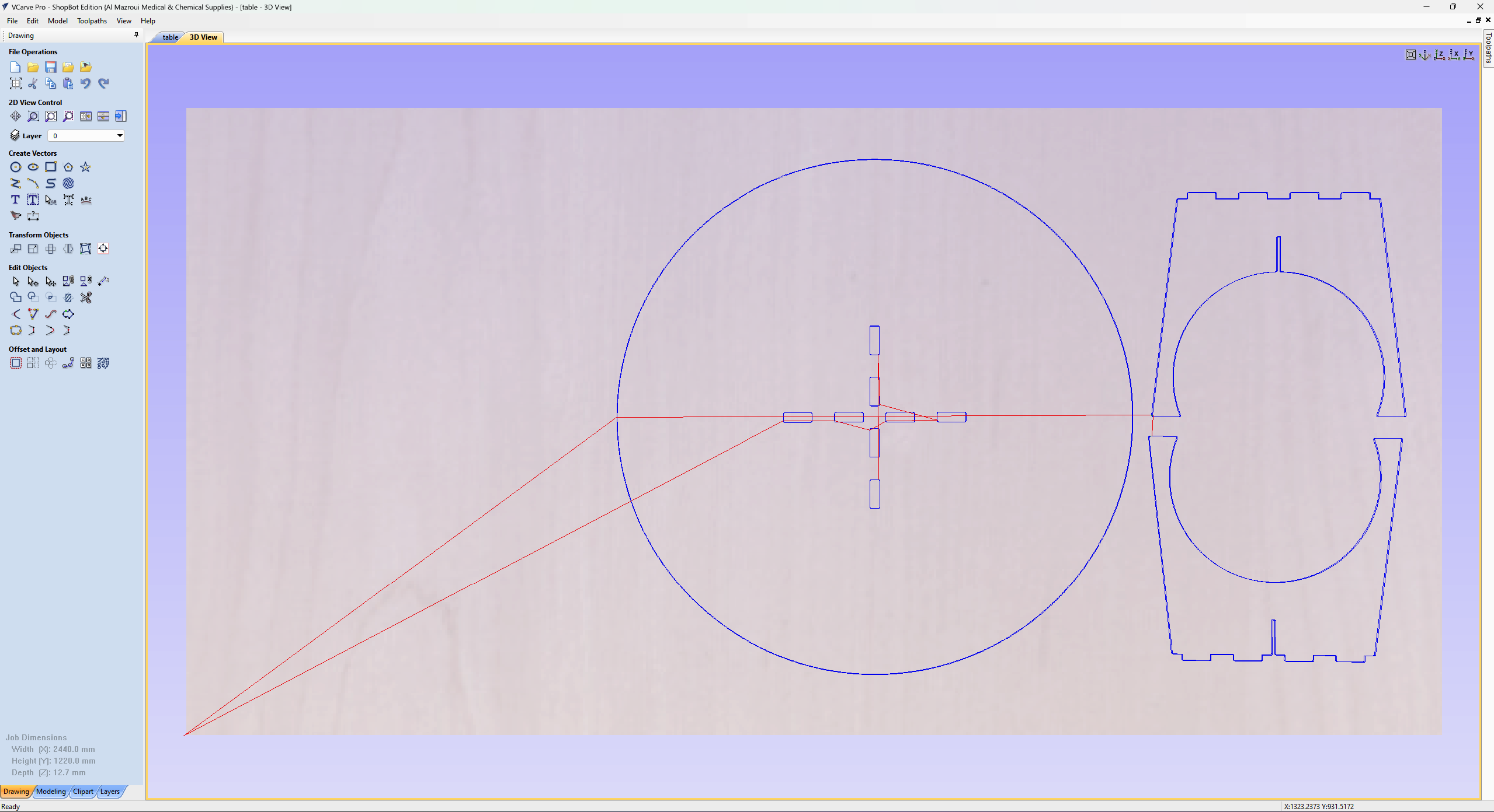
Opening Vcarve Software.
Select create a new file. Next a new job setup page will pop up.
Enter the below setting as shown :
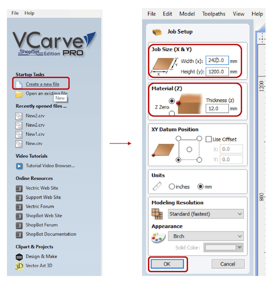
1. Setting Job Size (X & Y):
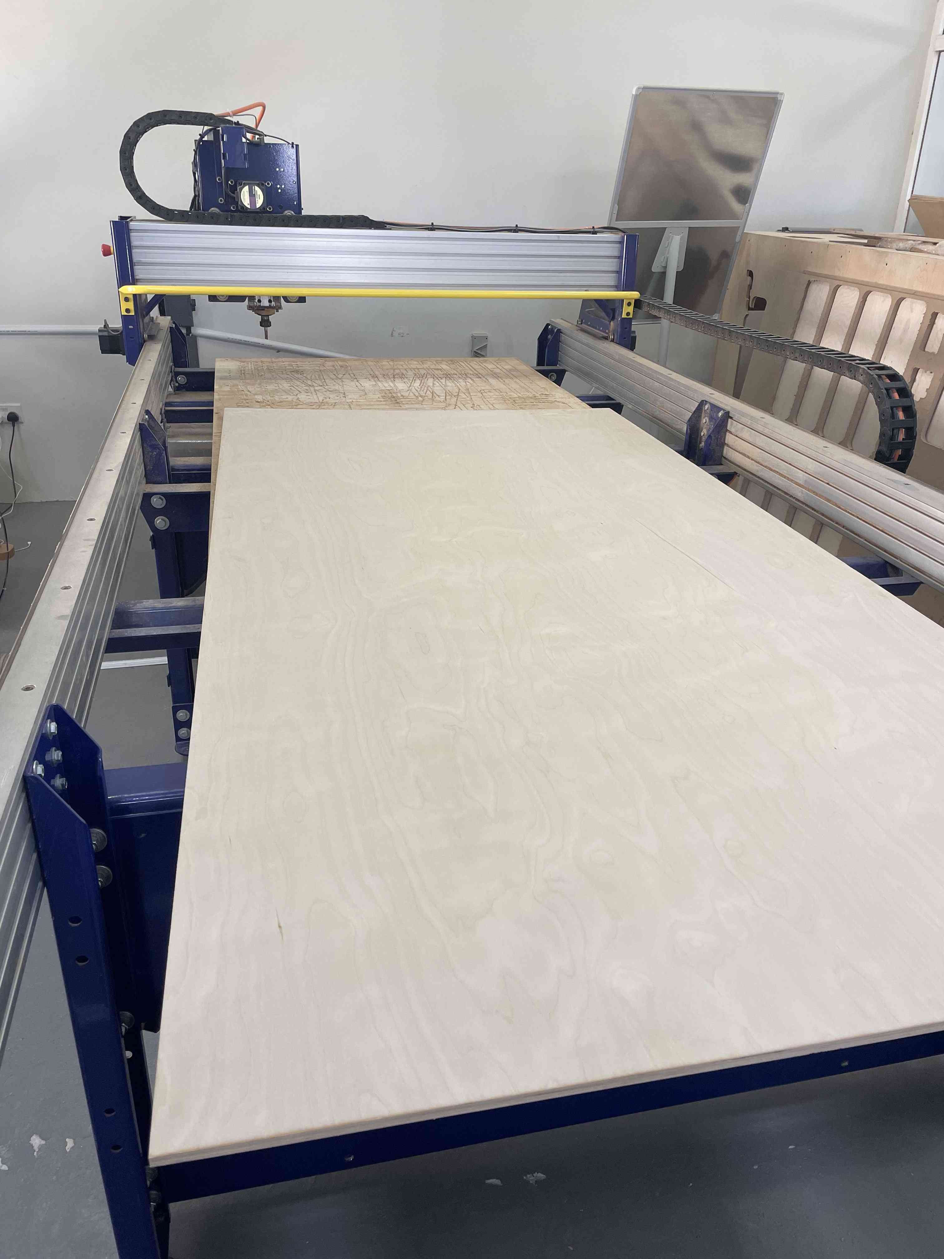
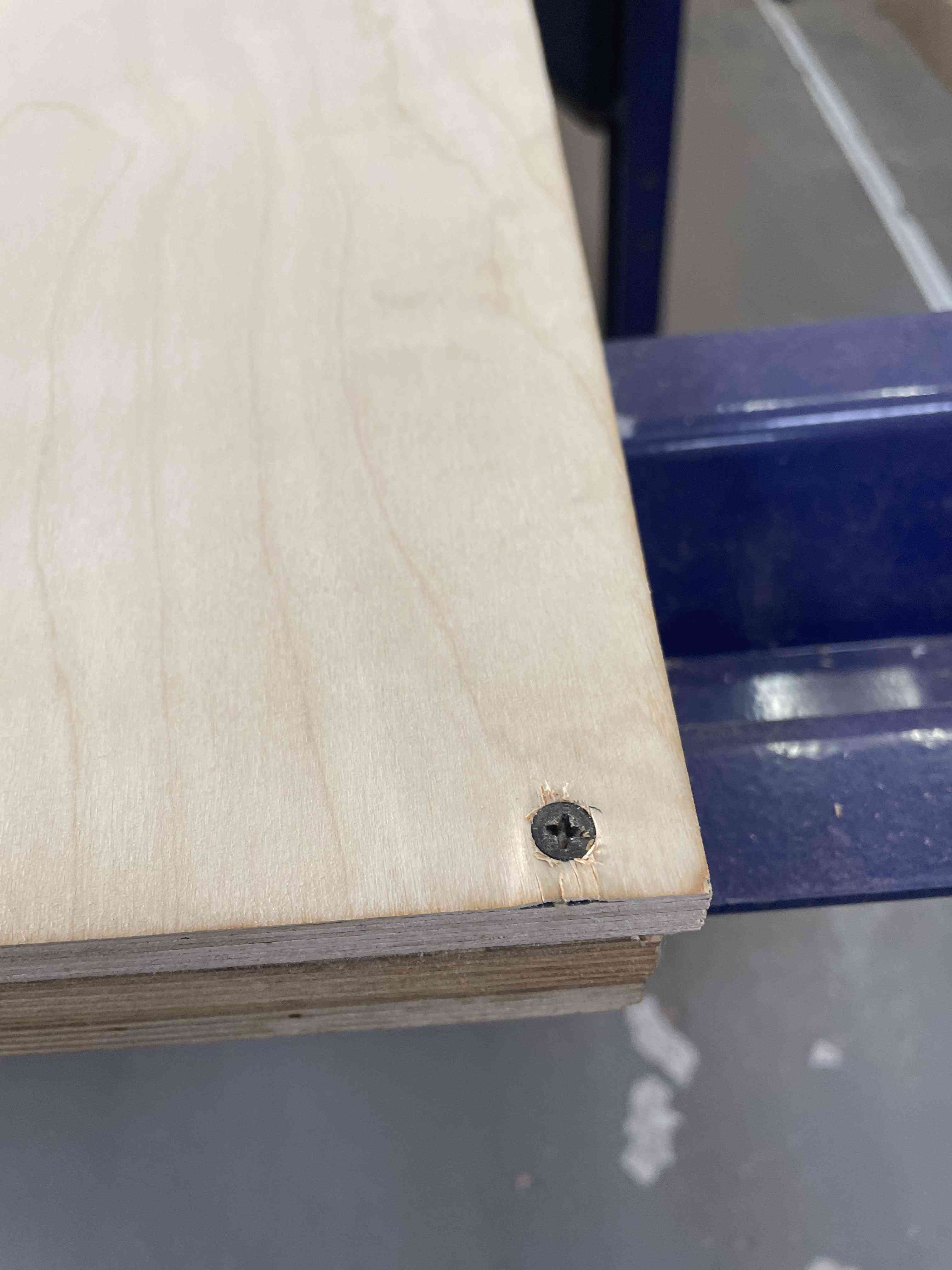
Sheet dimensions X(Width): 2420 cm and Y(Hight): 1200 cm, The original size of sheet is 2440 X 1220 cm, But I enter it smallest by 20 cm to ensure the tool will not hit the screws, because it’s may lead to risk.
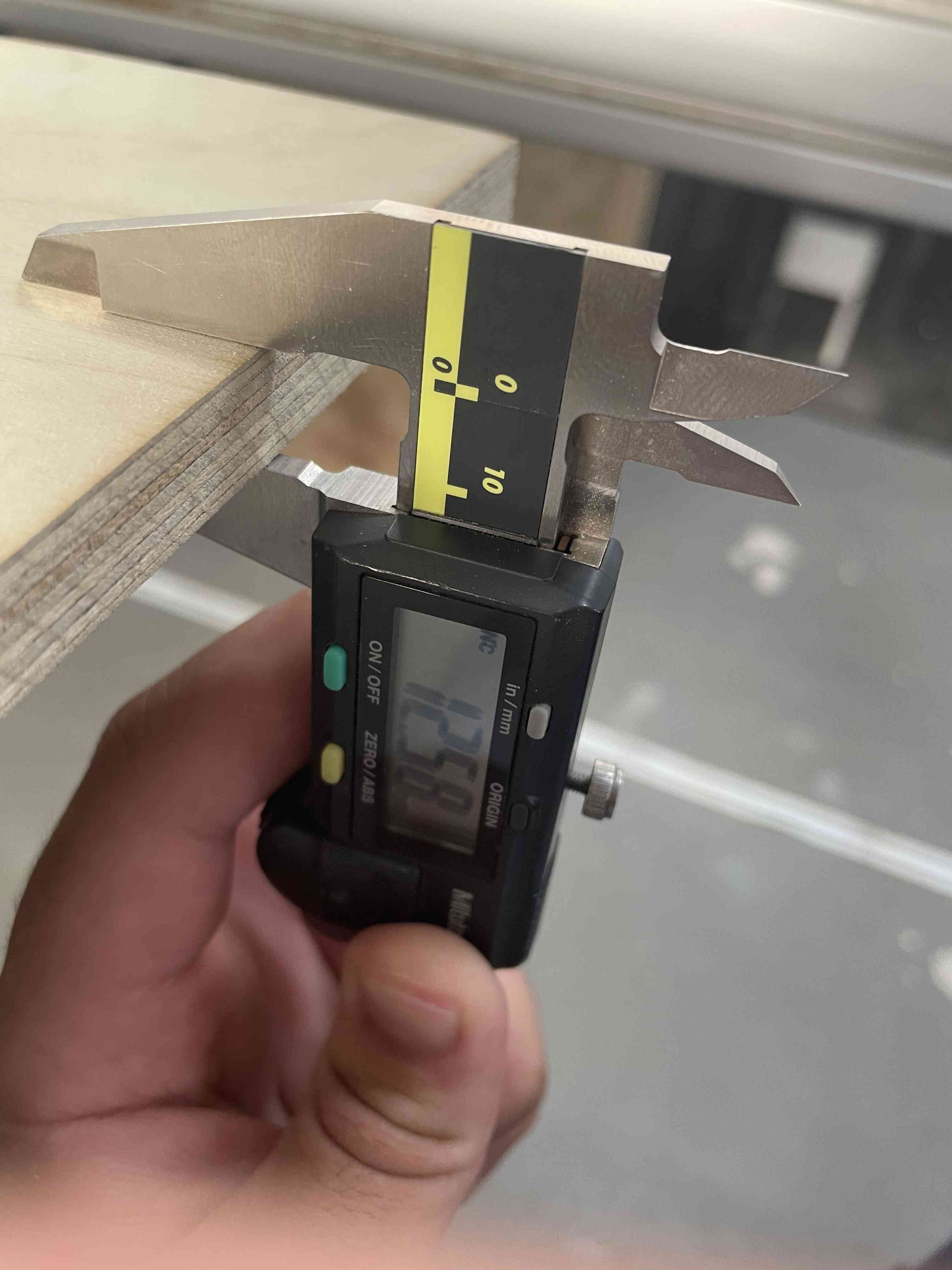
2. Material (Z): Enter the sheet thickness = 12.58 mm
Now the workspace is ready for importing designs.
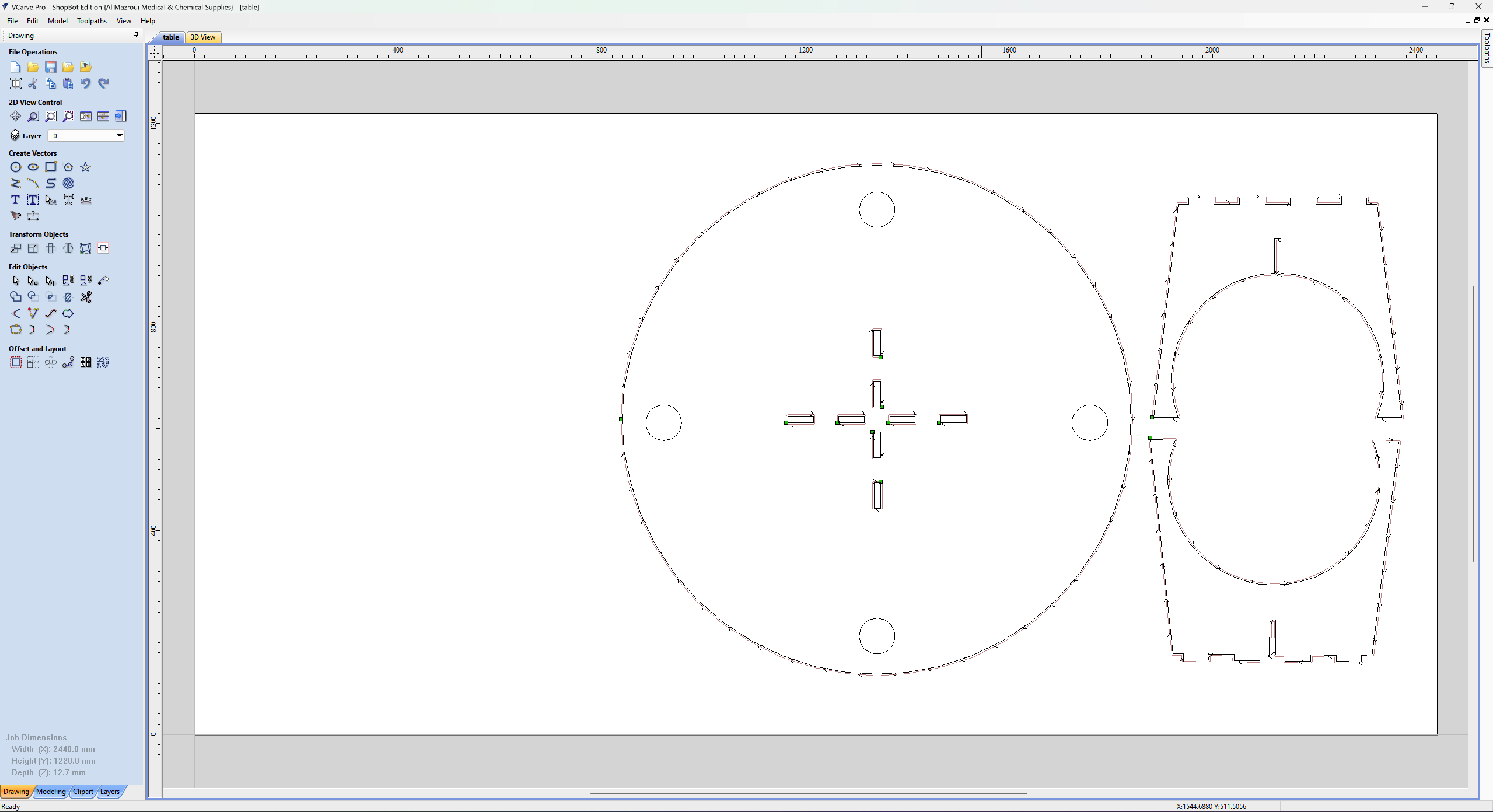
Vcarve, Go to File> Import>Import vectors: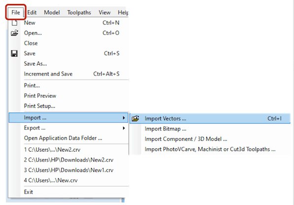
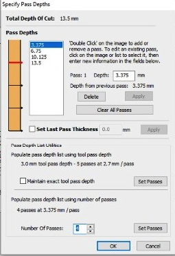
Next, I clicked on the toolpaths tab on the upper left, and selected the Profile toolpath. This is to cut the inner parts of the design, slots for example, first. And entered the following settings:
1- In cutting depths set the cut depth to 13.5 mm to ensure that the pieces are cut all the way through.
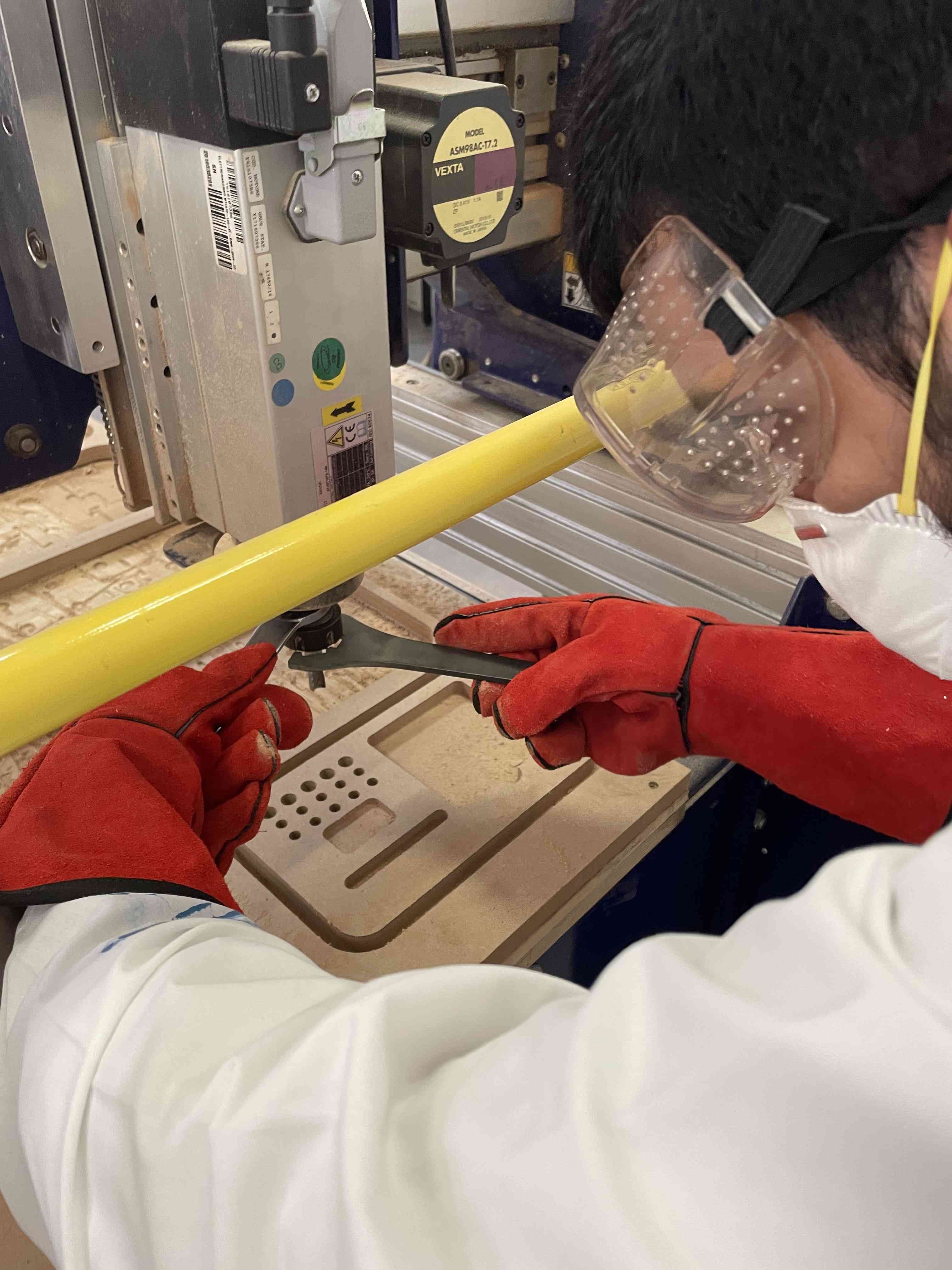
2- In tool select the 6mm End Mill, set the spindle speed to 14000, the feed rate to 60, plunge rate to 10 and edit the number of passes to 5 passes. Increasing the number of passes allows the end mill to go down a certain depth at a time, if not the high load on the tool may damage the end mill.
3- In machine vectors select inside/left, and select climb for the direction.
4- Check the add tabs box at the end, and set the tab length to 8mm and the tab thickness to 3mm. Adding tabs will prevent the pieces from moving or flying away while milling.
5- Lastly, click on calculate to generate the toolpath.
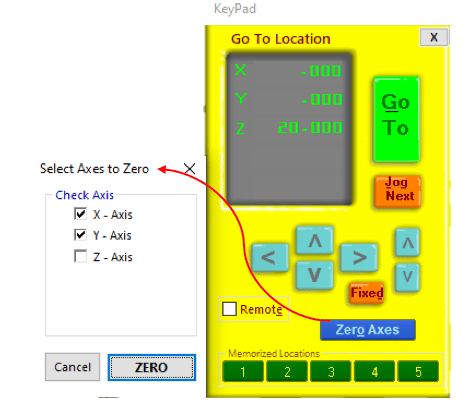
To start working, the origin points for the milling have to be set. This is done by accessing the Shopbot Control Software, and calibrate the XYZ values using the position keypad. To calibrate the XY positions, we shift the machine using the arrows on the keypad or using the keyboard, to position required, then click on zero axes and tick the x and y zero boxes.

Summary milling steps:
Set zeros.
Cut parts.
Clean the sheet.
Remove parts.
Sanding.
Assemble.
To move and give orders in ShopBot we use: 1. Control panel. 2. KeyPad.
| Control panel | KeyPad |
|---|---|
| Provides main machine information and controls | Used to manually move the X,Y, and, Z axes |
| used to move the router to set XYZ axes | moving the spindle and XY axes by using the blue arrows. |
| Giving order of cutting parts | - |
To open the KeyPad, by clicking the yellow box in the control panel:
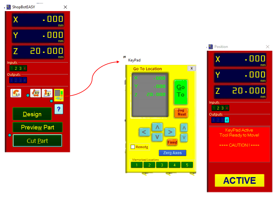
First thing to do is setting zero of X- and Y-axes , the shopBot it self has its own zeroes points. the machine will move until hitting the limit switch for X and Y this process called proximity switch homing process. which creates an accurate and repeatable start point.
Manually, I moved the XY axis for the wanted place in the sheet, Then I selected my own zeros of X and Y from KeyPad as shown:
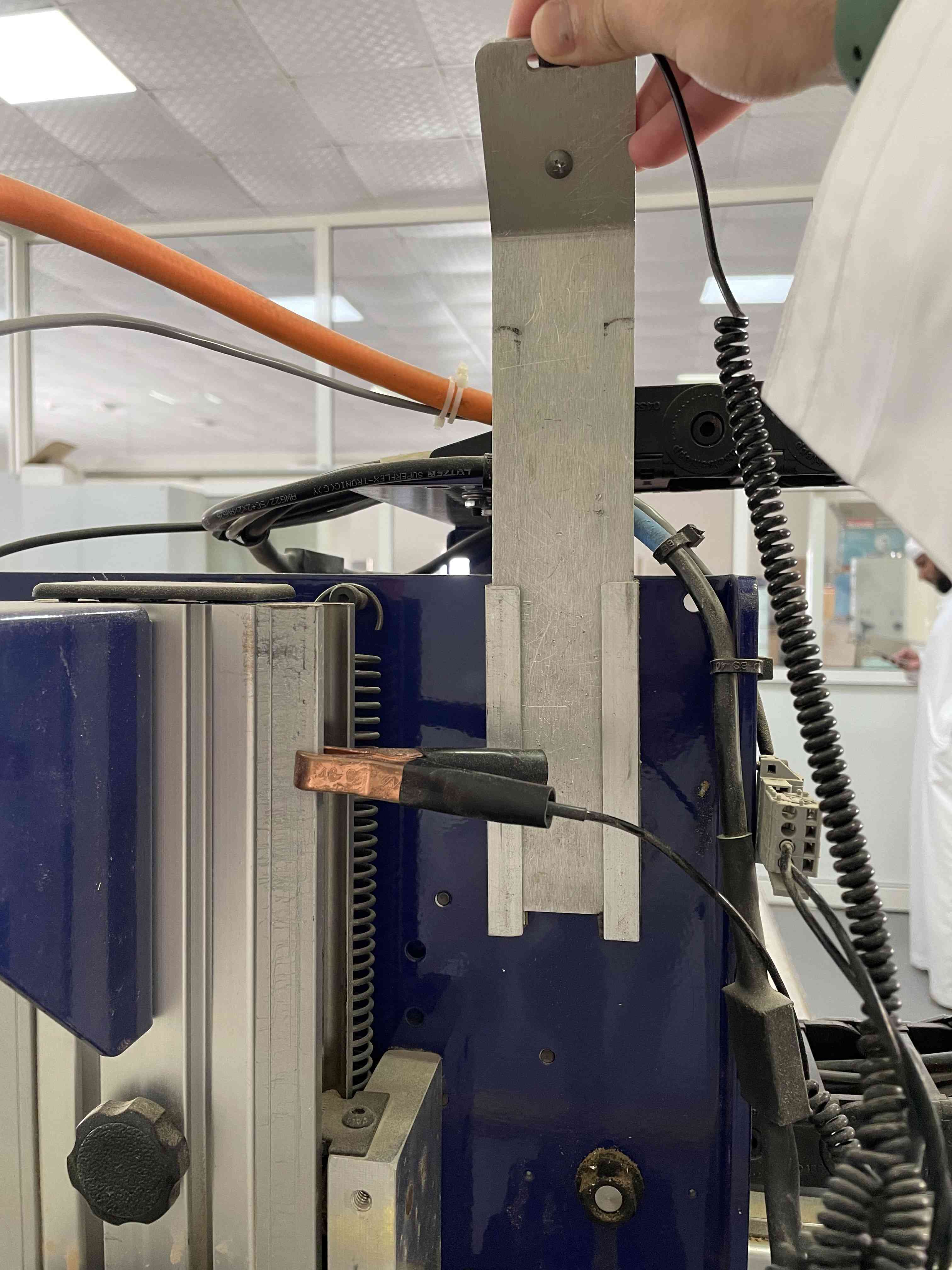
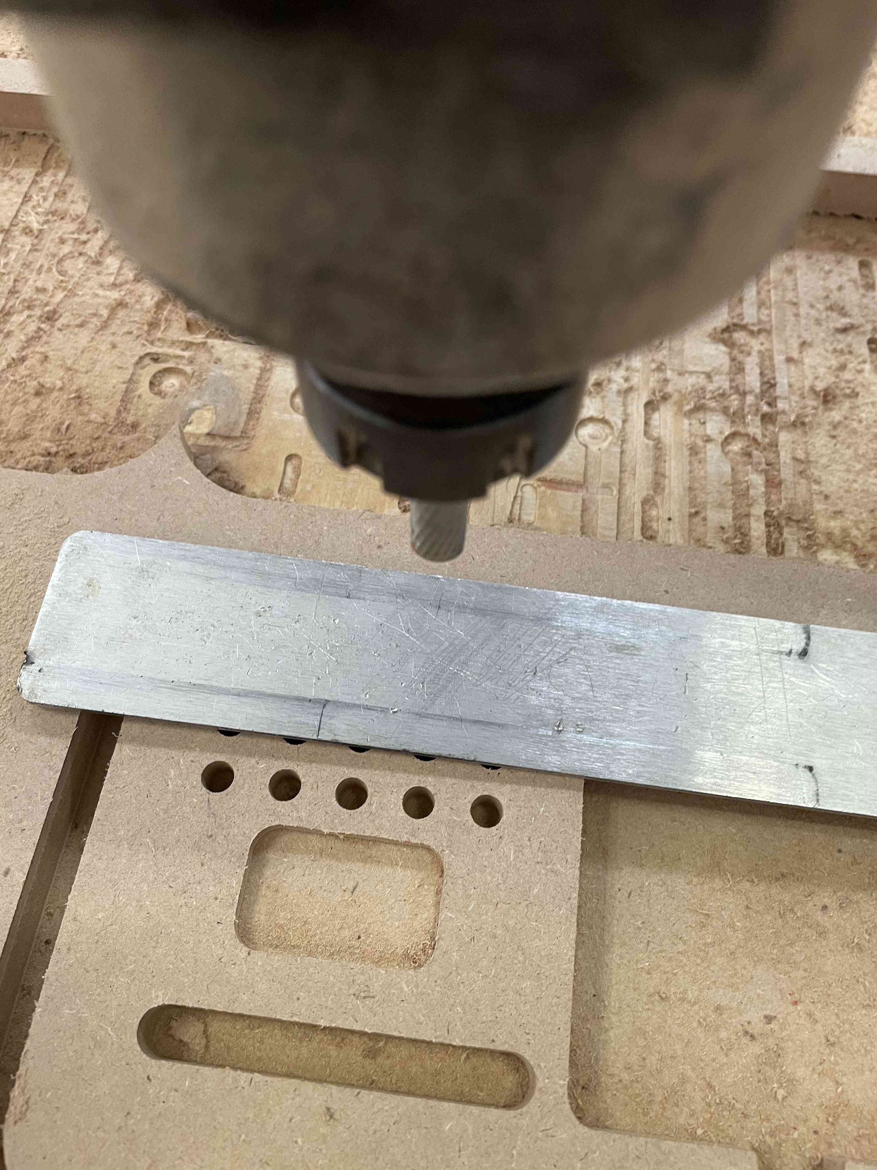
The Z-axis must be zeroed each time that the machine is turned On or bits are changed. The process of setting the zero for Z axes done automatically. First, I move the tool to empty place, where is no holes or anything, and take the router up.
Next, using the metal plate, by put it under the bit, then from the software I click set zero, the Z axis will go down to touch the plate for three times. This operation will set the Z to zero.
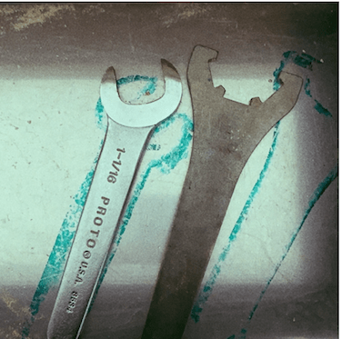
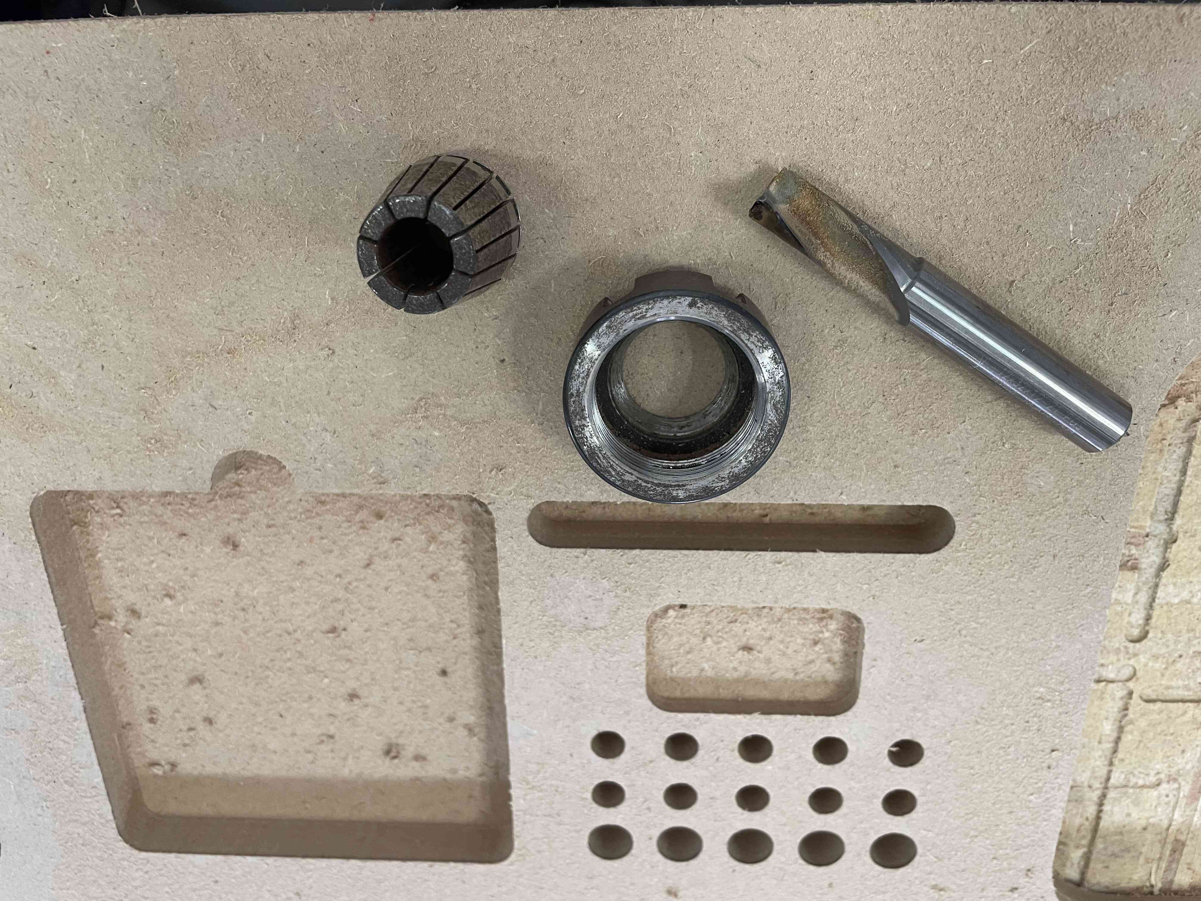
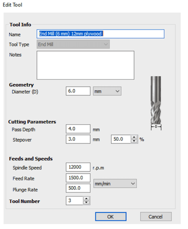
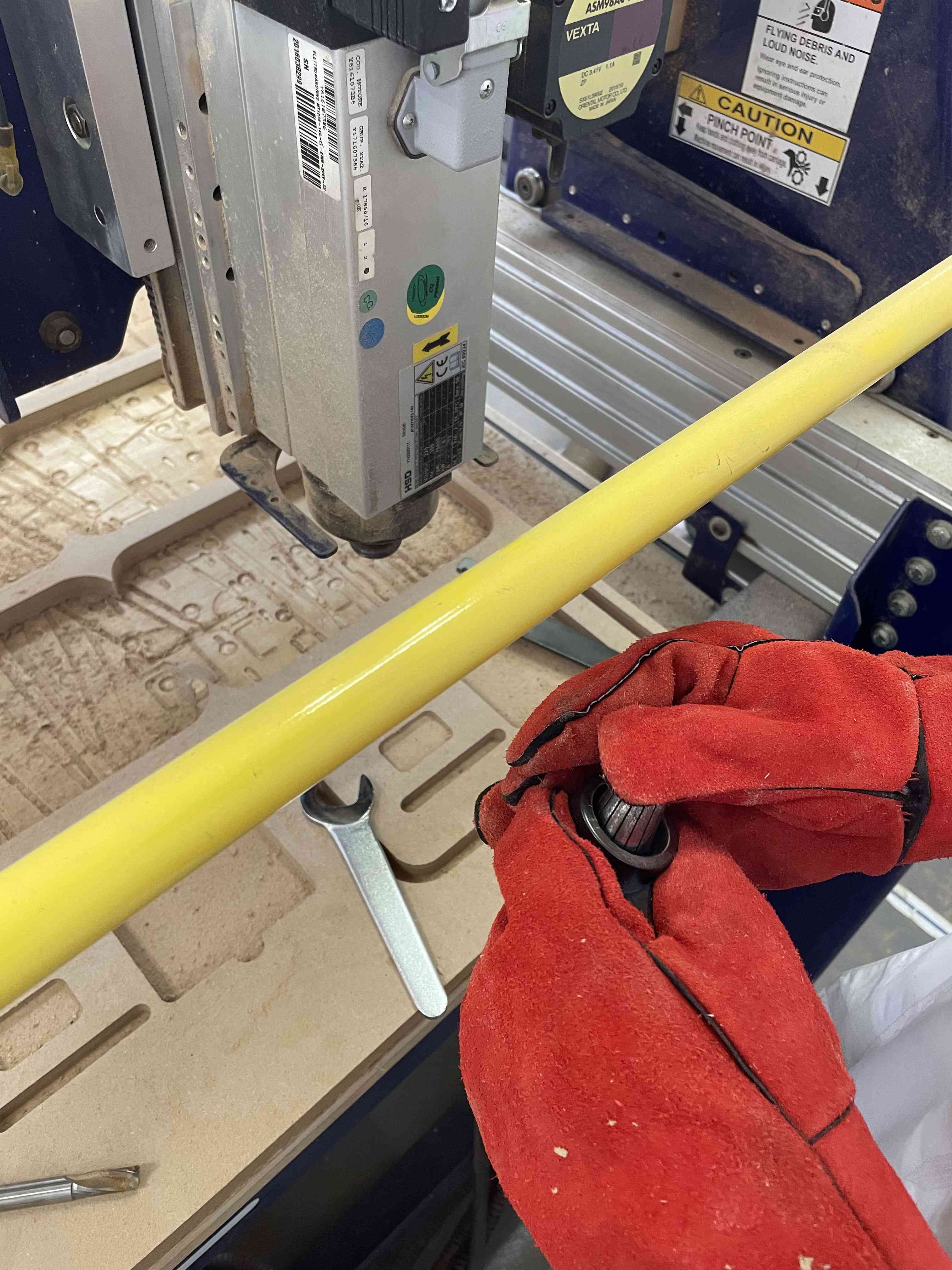
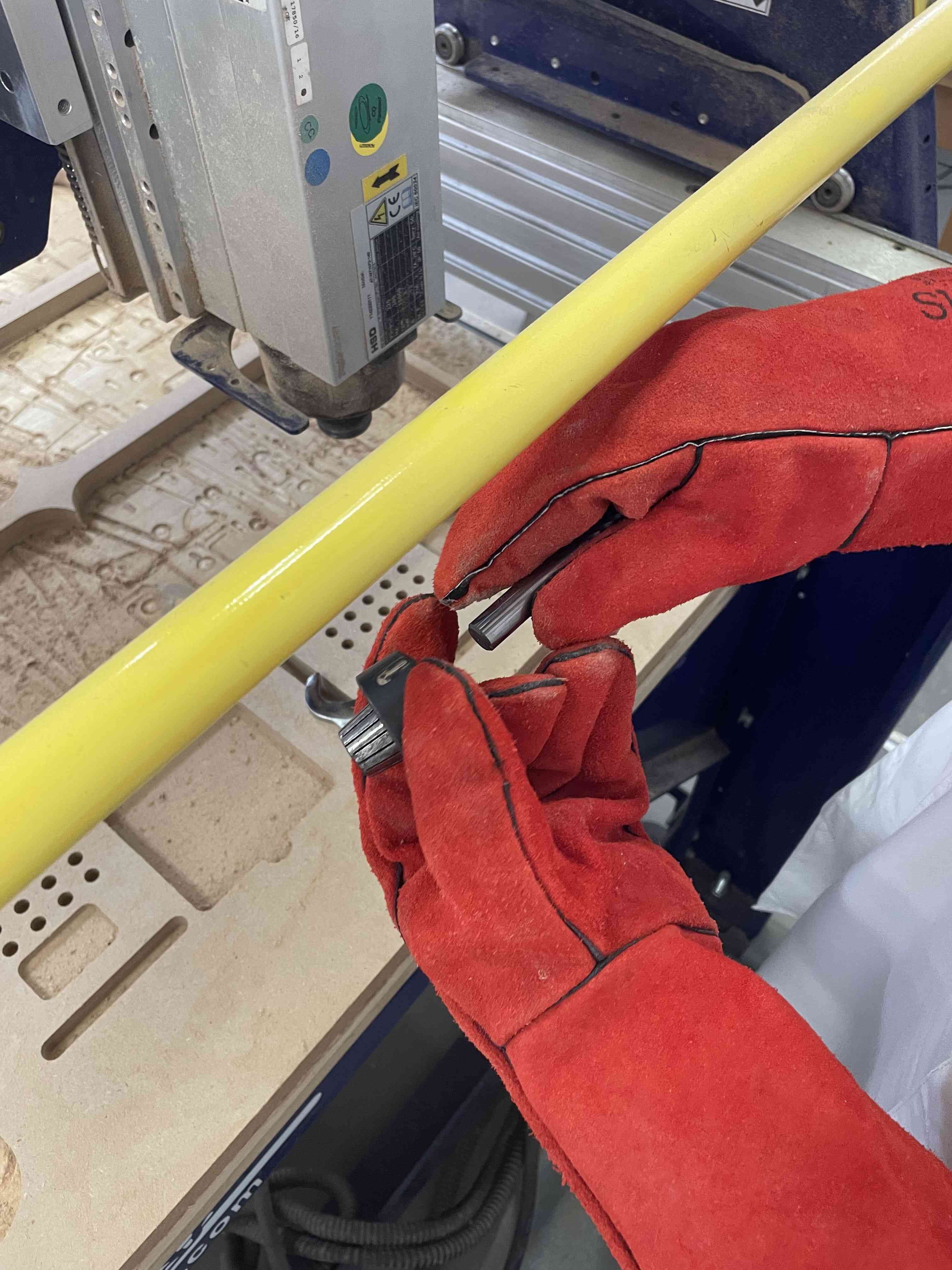
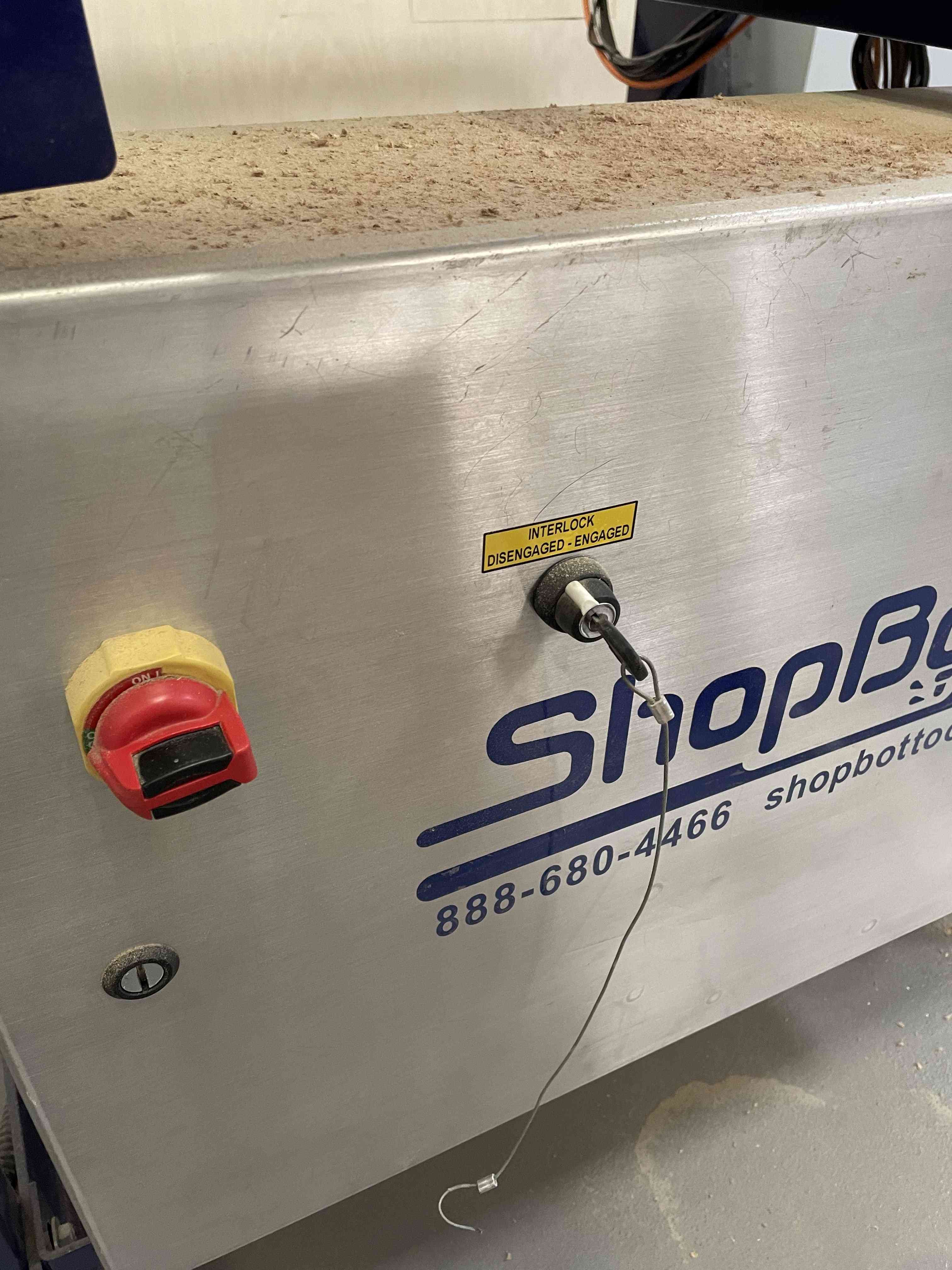
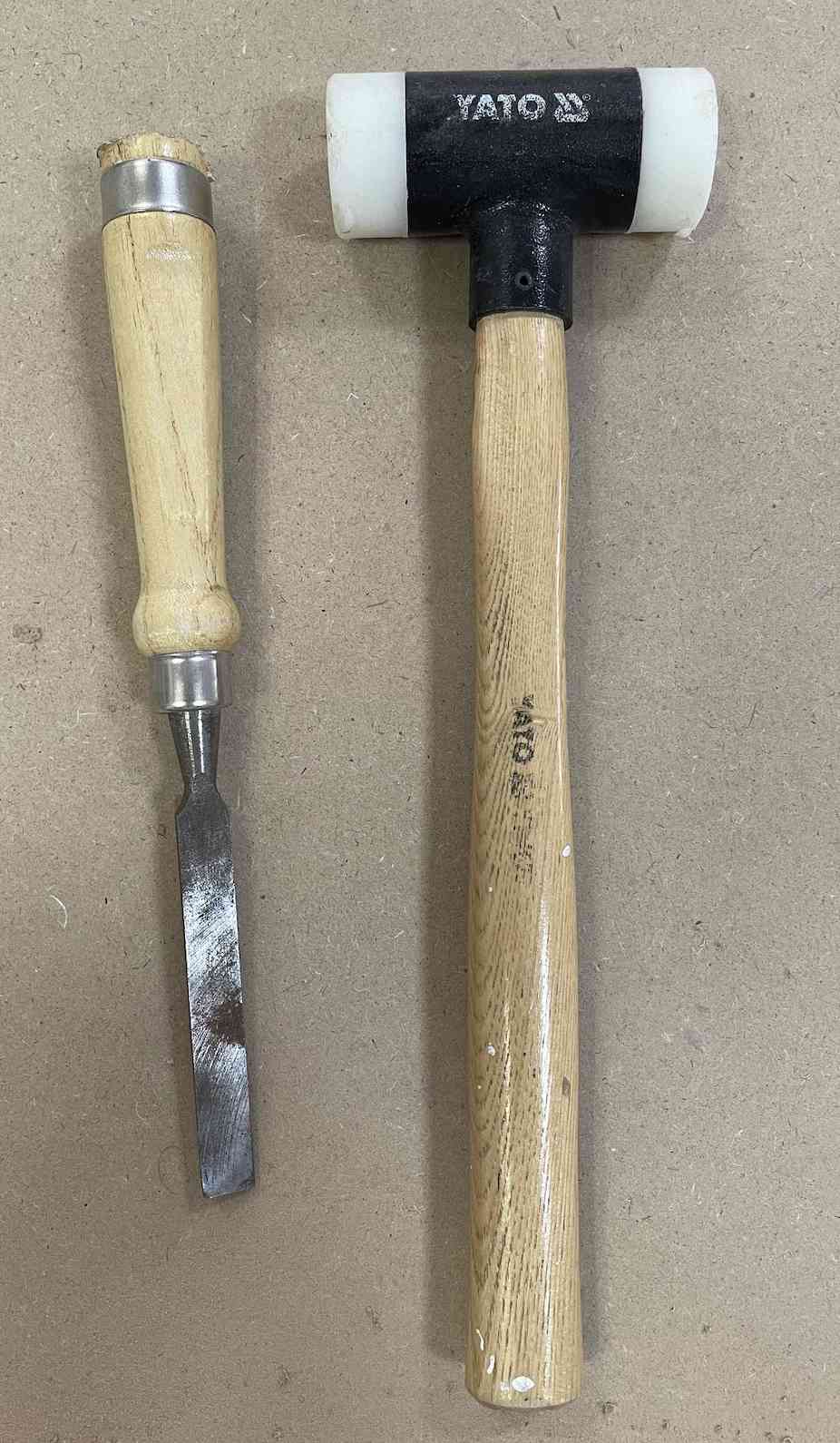
I used two tools for milling the design. Thus, I had to change the tool bits. For changing the tool I need to use these two wrench shown below in the image, this wrench is connected to the key with shopBot for safety reasons. So the machine will turn off while changing the tool, to avoid any unaccepted moves from the machine.
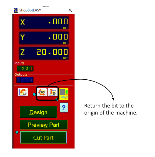
Now the zeros is set up to the origin points. I can start cutting the parts.
They are two ways to start milling:
Cut Part at control panel as shown below: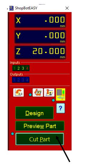
After clicking on the cut part some warnings will pop out, we had to read and follow the instruction.
Finally to start milling click on start at the remote control.
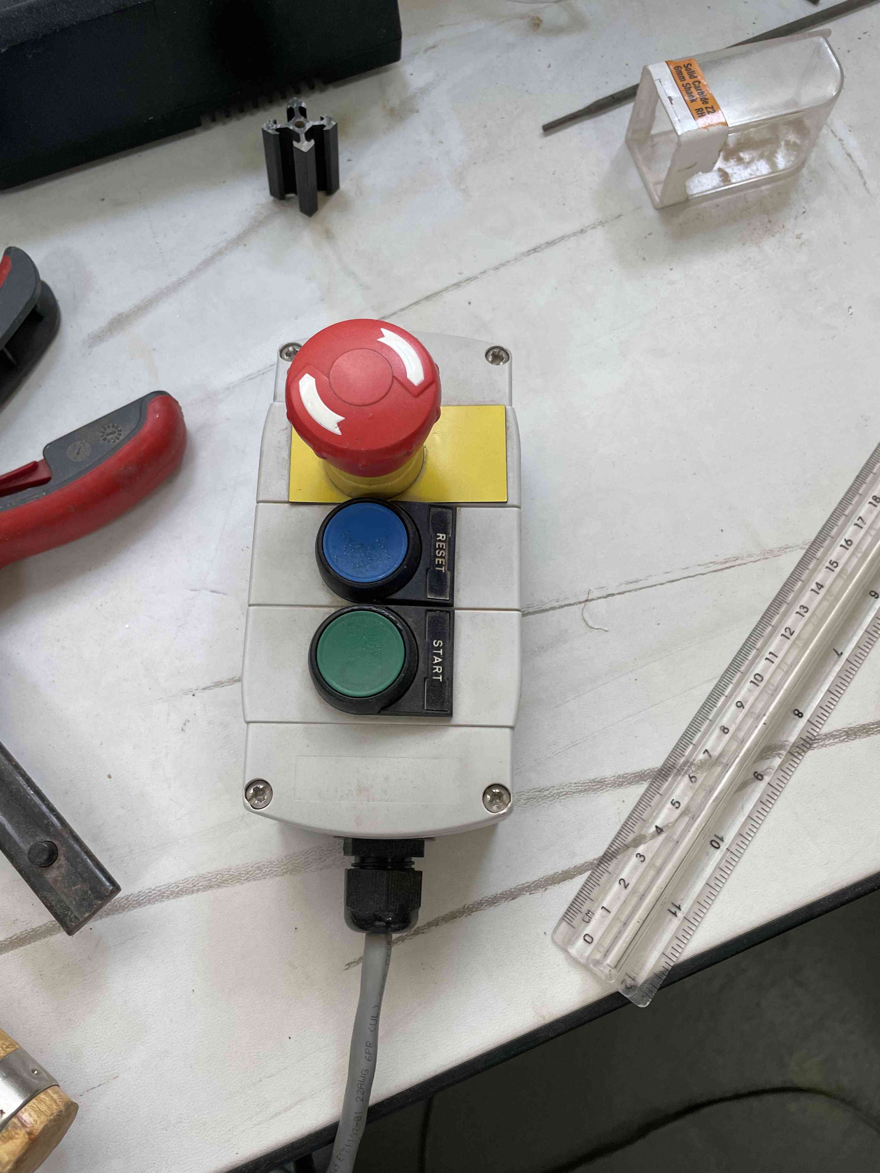
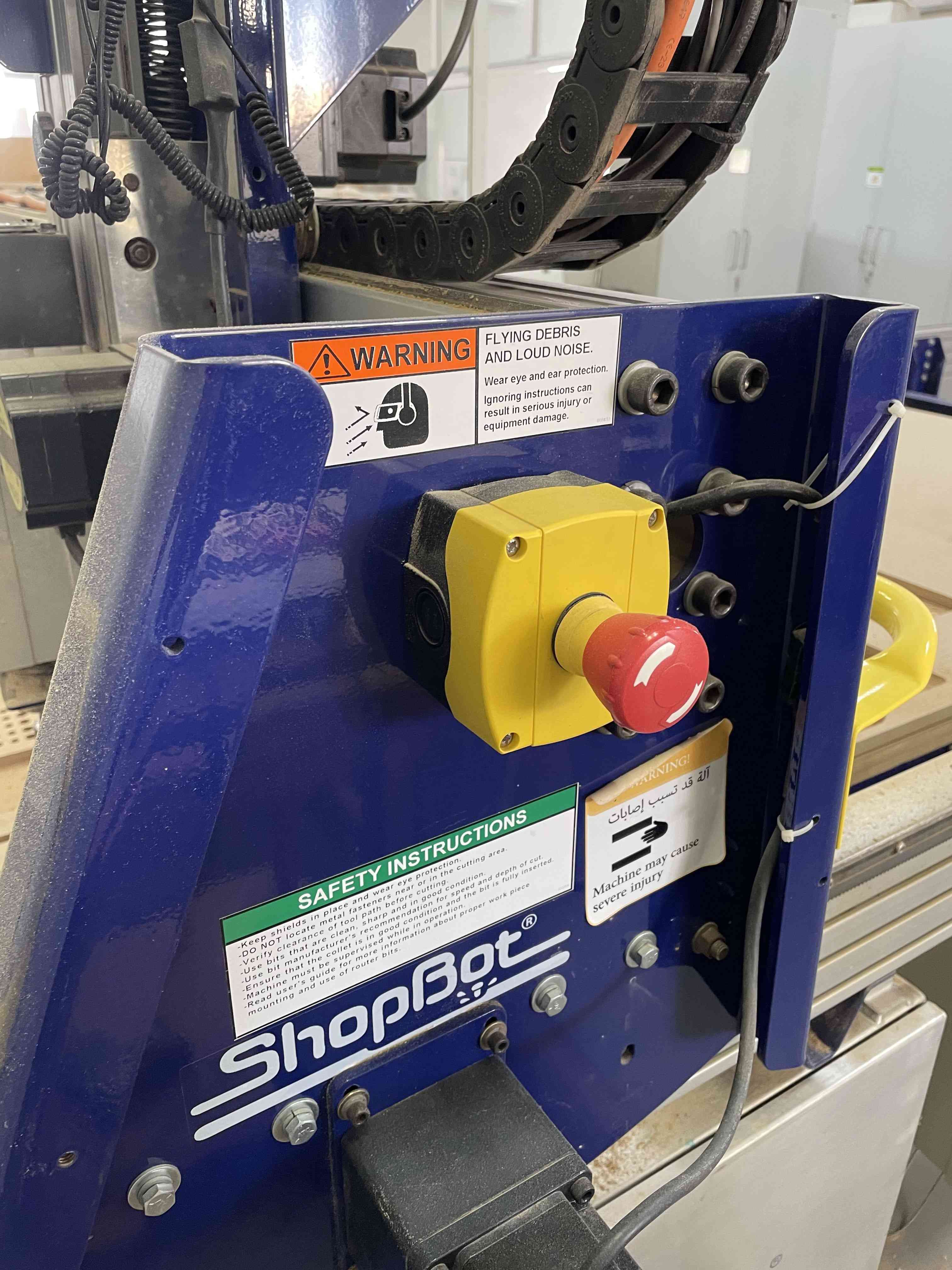
Additionally, for safety reasons I must monitor the shopBot while milling all the time. and I must to keep the remote control near to me in case I need to stop the machine using the emergency switch, also I had to stay far from the shopbot for safety reasons.
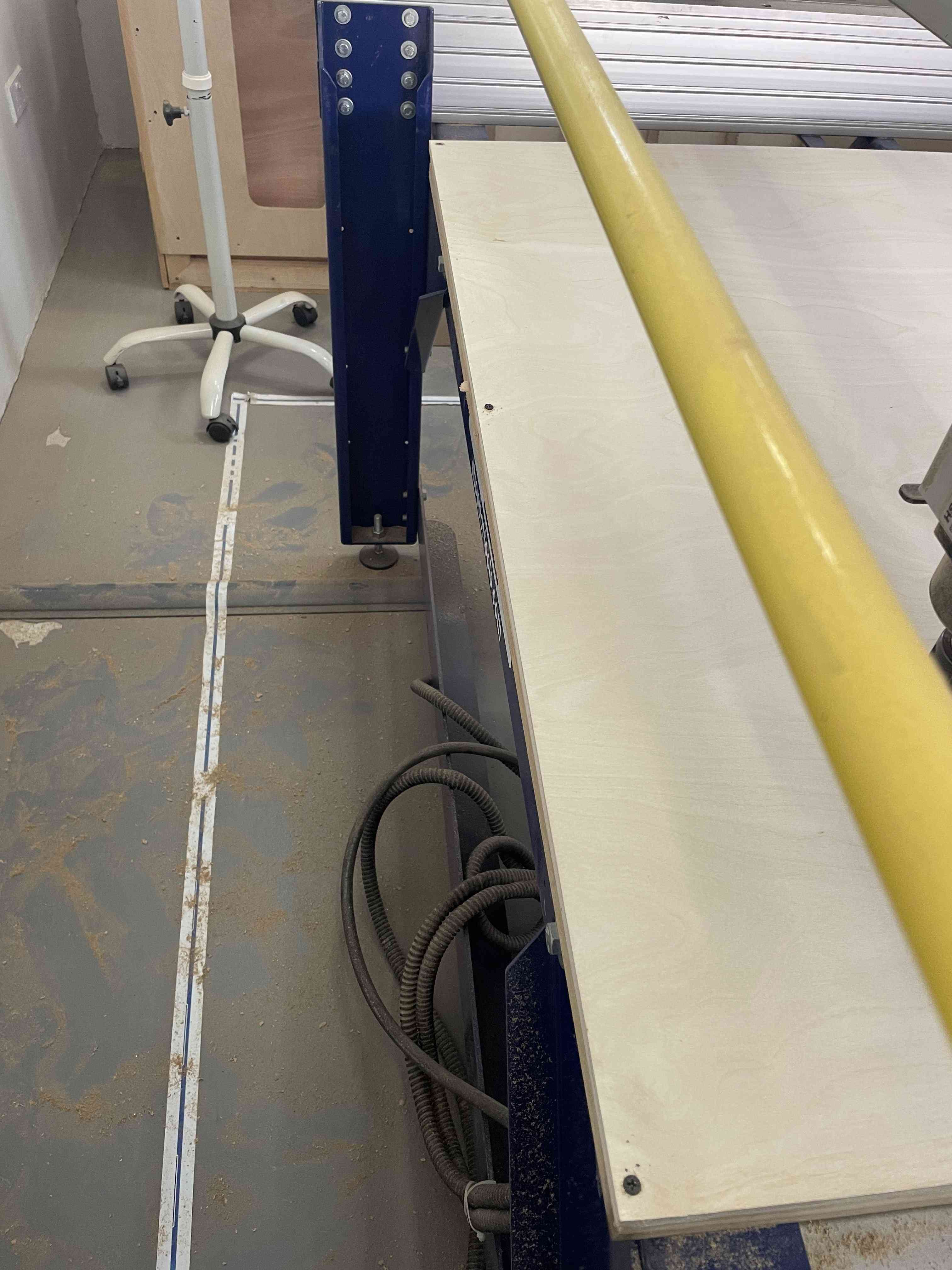
Next, I did sanding the parts.
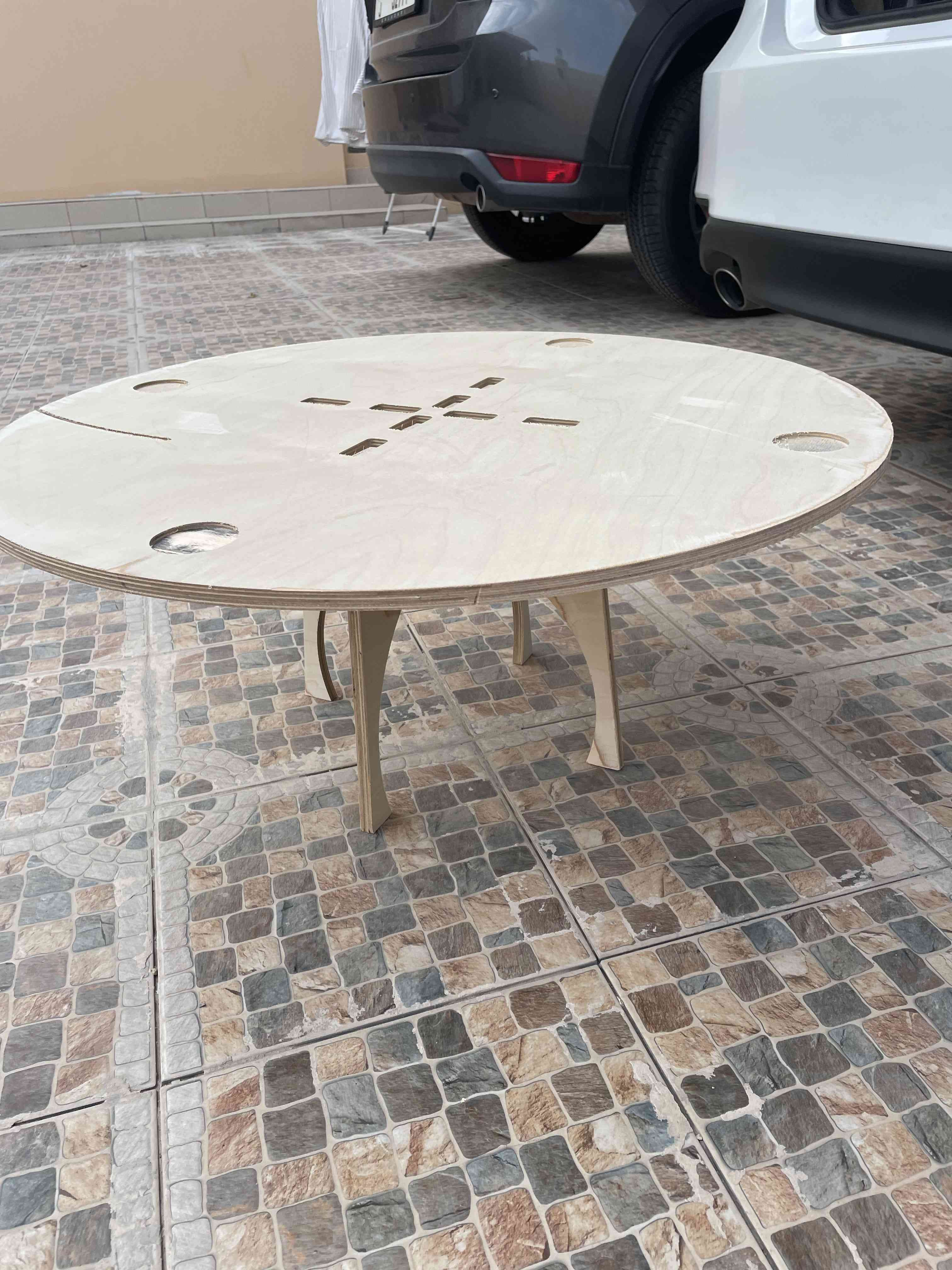
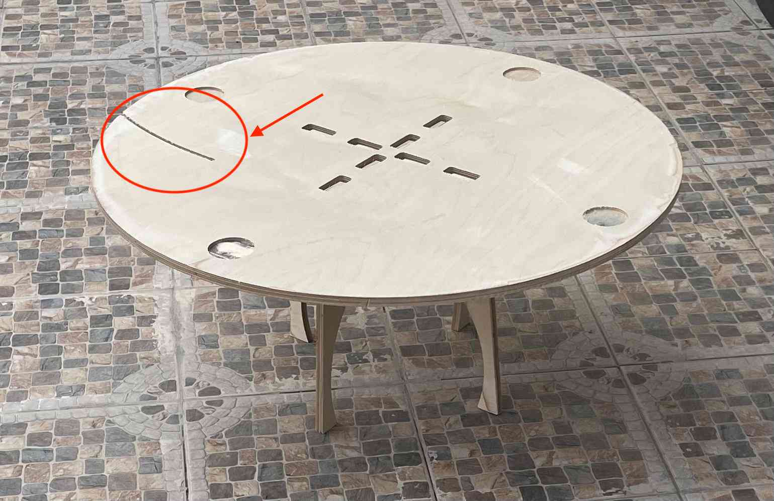
And, about the scratch on the table, It was from old failed run and it cut only one or 2 layers do instead of wasting wood I deside to use the same wood.