Abdalla:
Arduino IDE Arduino is a very popular and most commonly used open-source electronics platform based on easy-to-use hardware and software. Arduino is fundamentally a C/C++ environment. It runs a simple programming language called Wiring, which makes it easy to write scripts to make the microcontroller carry out tasks. These scripts are called Sketches by Arduino. Most shields come with sketches already written that can be loaded in to the software, compiled and downloaded to the base board.
Advantages:
Cross-platform - runs on Windows, Macintosh OSX, and Linux operating systems. Most microcontroller systems are limited to Windows.
Easy to learn with a lot of online resources to learn
Huge supporting community.
Simple, clear programming environment - easy-to-use for beginners, yet flexible enough for advanced users to take advantage of as well.
Open source and extensible software - The Arduino software is published as open source tools, available for extension by experienced programmers. The language can be expanded through C++ libraries, and people wanting to understand the technical details can make the leap from Arduino to the AVR C programming language on which it’s based. Similarly, you can add AVR-C code directly into your Arduino programs if you want to.
Disadvantages:
No understanding of the AVR microcontroller.
Sketches and shields can be difficult to modify.
No debugger included for checking scripts. When errors arise, some do not have a clear statement of where or why this error message is showing, it won’t direct you or give solution unless you have experience with Arduino.
For using with Attiny. Attiny 44 in our case, we need to install the package, it is also required to burn the Arduino bootloader onto the chip to make sure the chip will accept any programs uploaded via the Arduino IDE.
what is Microcontrollers & Embedded programming.
Know the I/O & Hardware Connection for the pins
How to setup "Seeed Studio XIAO RP2040" with Arduino
A microcontroller is a small and low-cost microcomputer designed to perform the specific tasks of embedded systems like displaying microwave information, receiving remote signals, etc.
The general microcontroller consists of the processor, the memory (RAM, ROM, EPROM), Serial ports, peripherals (timers, counters), etc.
Embedded programming is the process of creating software for tiny, specialized computer systems that are built into various gadgets, including household goods, automobiles, medical devices, and industrial machinery. These systems frequently have minimal power, little memory, and poor processing capability since they are made to carry out particular tasks. In order to interface directly with the hardware components of the embedded system, embedded programming often entails writing code in low-level programming languages, such as C or assembly. Programming calls for a thorough grasp of the architecture of the system as well as the capacity to optimize code for effective use of system resources.
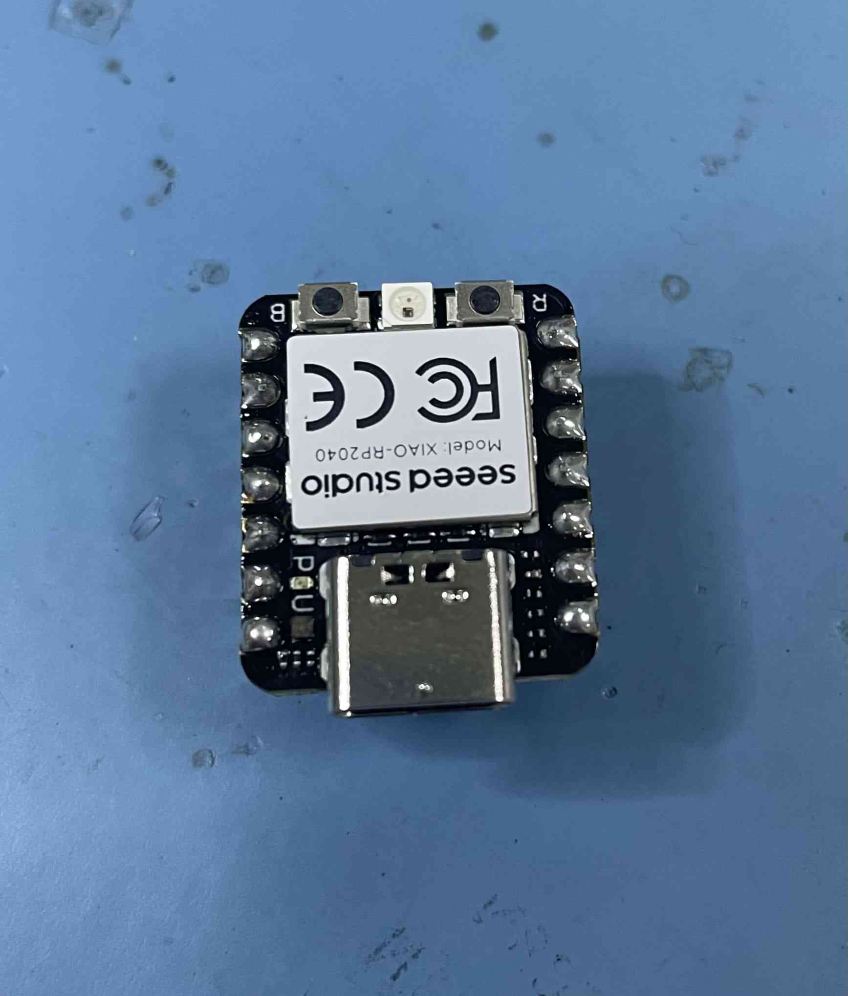
Seeed Studio XIAO RP2040 x1
The PC x1
USB Type-C cable x1
potentiometer x1
led - RGB color x3
Resistor 200-ohm
Breadboard x1
Jumper Wires
Photoresistor x1
We used "Seeed XIAO RP2040" for this week first let's know the pinout.
Powerful MCU: Dual-core ARM Cortex M0+ processor, flexible clock running up to 133 MHz.
Rich on-chip resources: 264KB of SRAM, and 2MB of on-board Flash memory.
Flexible compatibility: Support Micropython/Arduino/CircuitPython.
Easy project operation: Breadboard-friendly & SMD design, no components on the back.
Small size: As small as a thumb(20×17.5mm) for wearable devices and small projects.
Multiple interfaces: 11 digital pins, 4 analog pins, 11 PWM Pins,1 I2C interface, 1 UART interface, 1 SPI interface, 1 SWD Bonding pad interface.
We used "Seeed XIAO RP2040" for this week first let's know the pinout.
There are 14 GPIO PINs on Seeed Studio XIAO RP2040, on which there are 11 digital pins, 4 analog pins, 11 PWM Pins,1 I2C interface, 1 UART interface, 1 SPI interface, and 1 SWD Bonding pad interface.
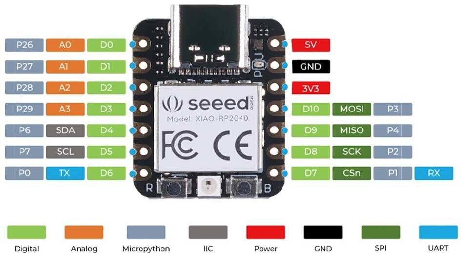
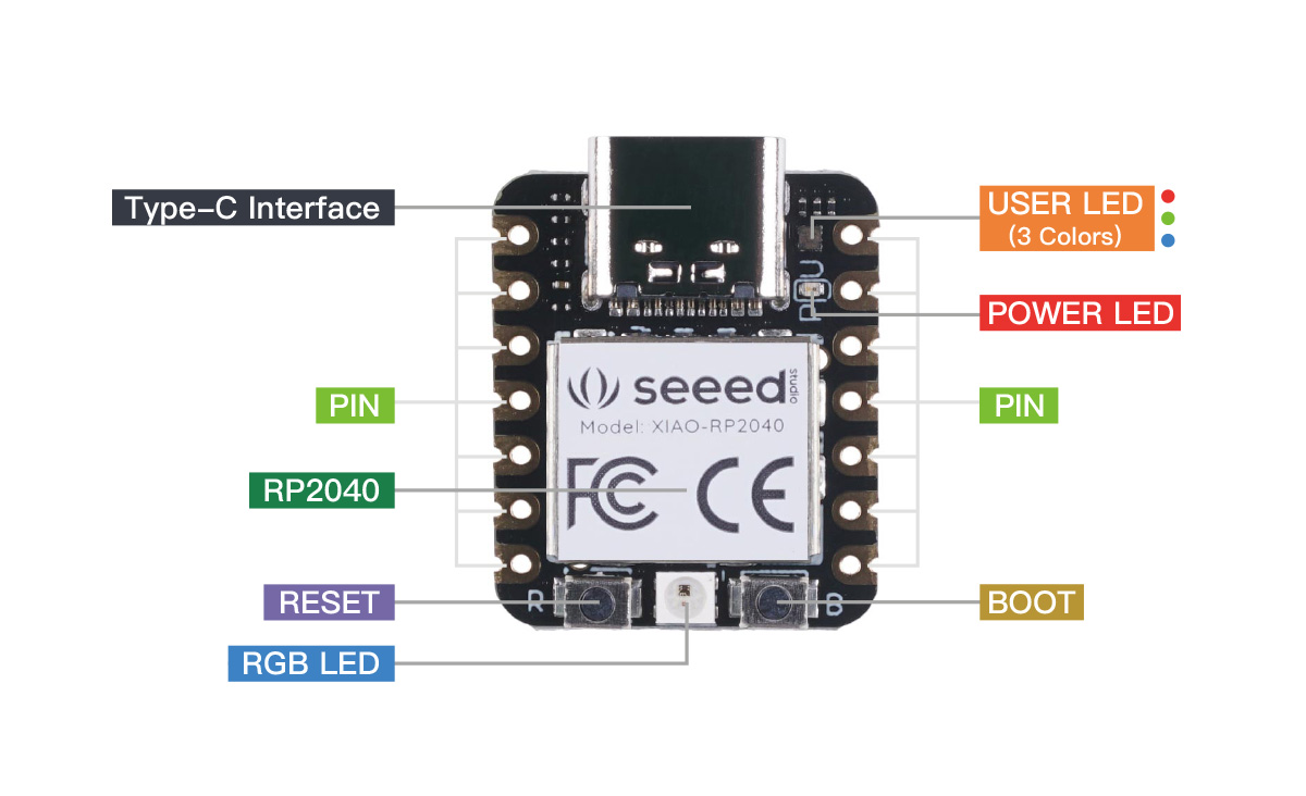
The working voltage of the microcontroller is 3.3V. Voltage input connected to general I/O pins may cause chip damage if it is higher than 3.3V.
Step 1: find a good environment
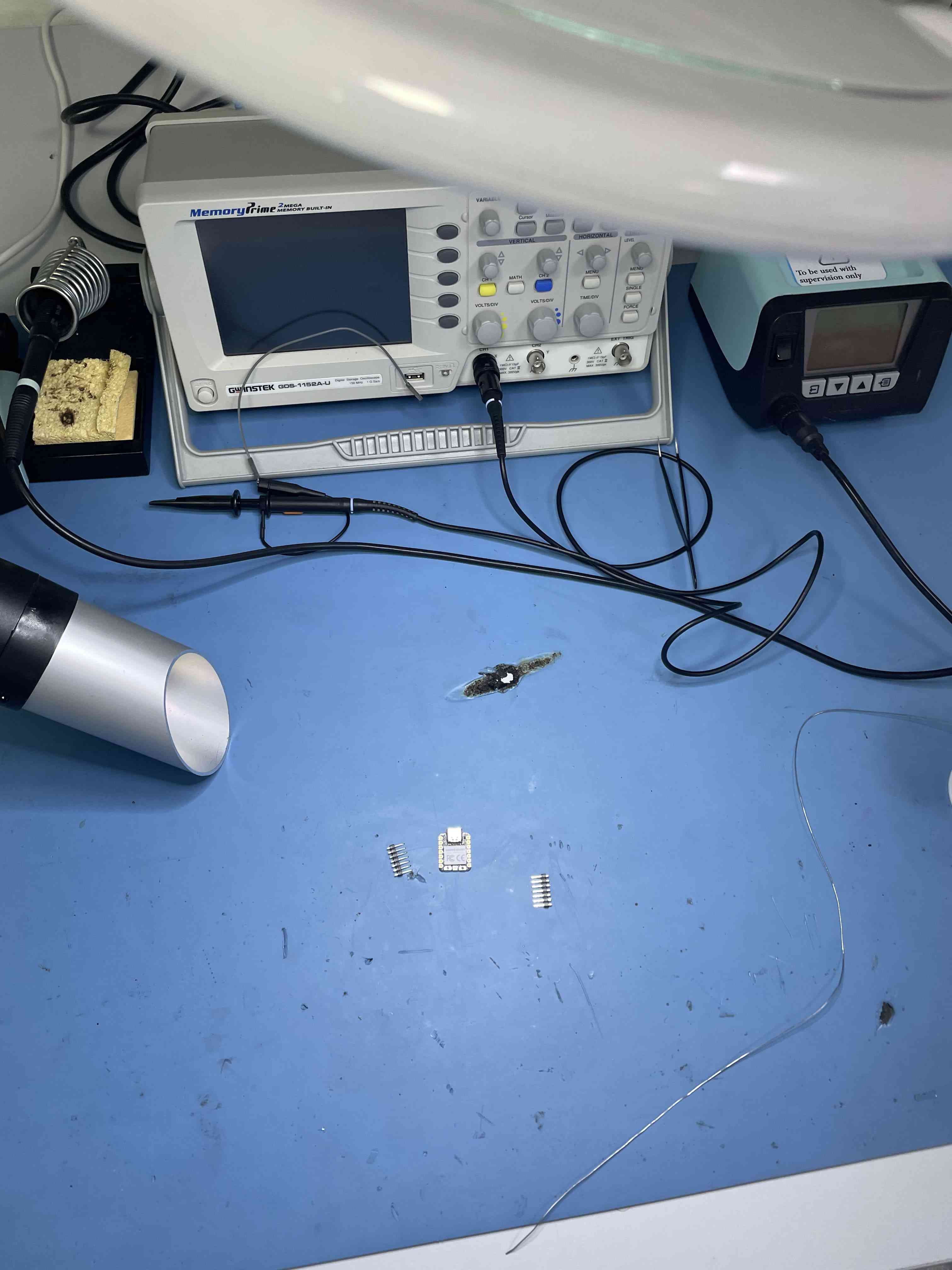
Step 2: aline the pins legs
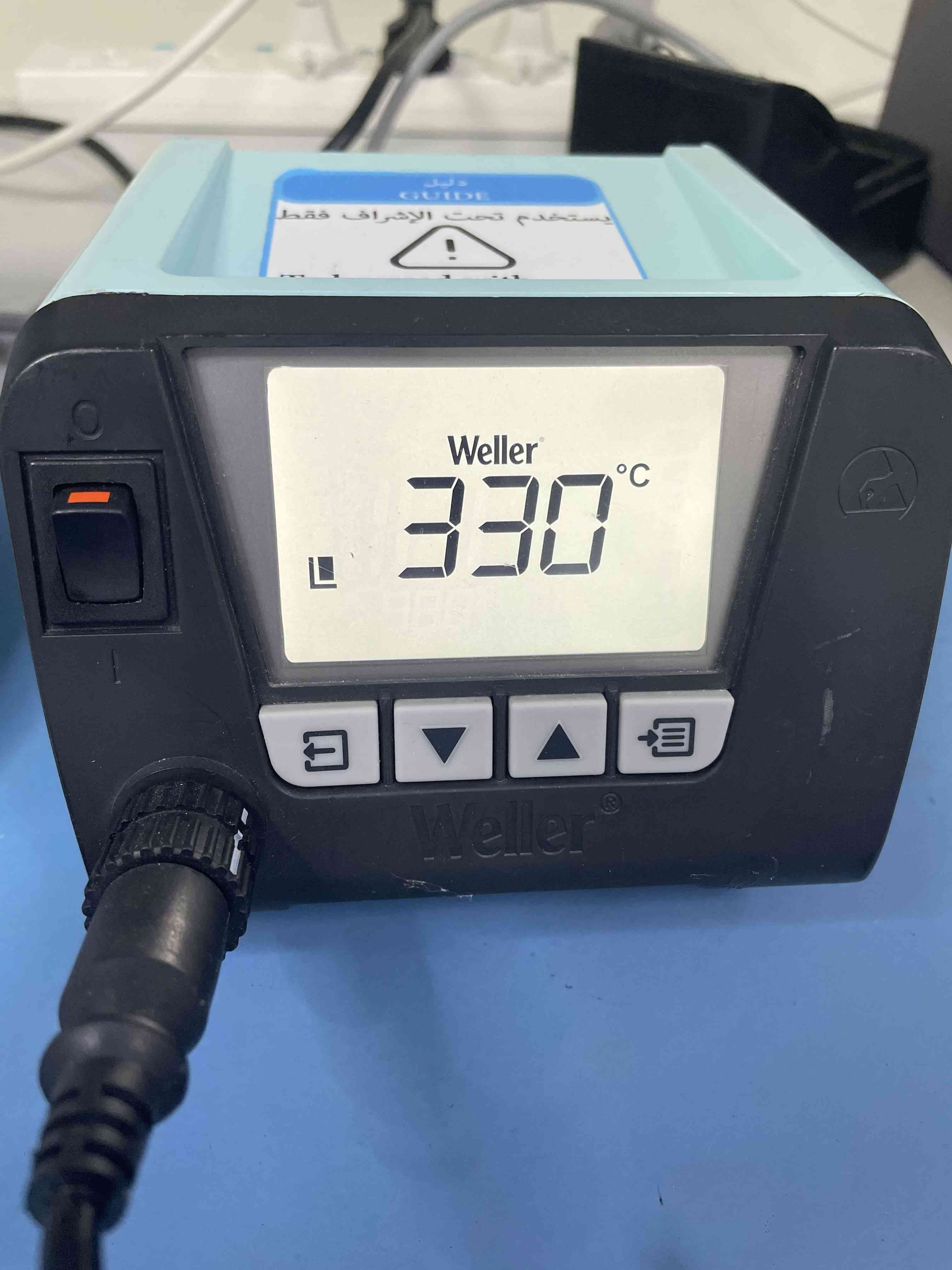
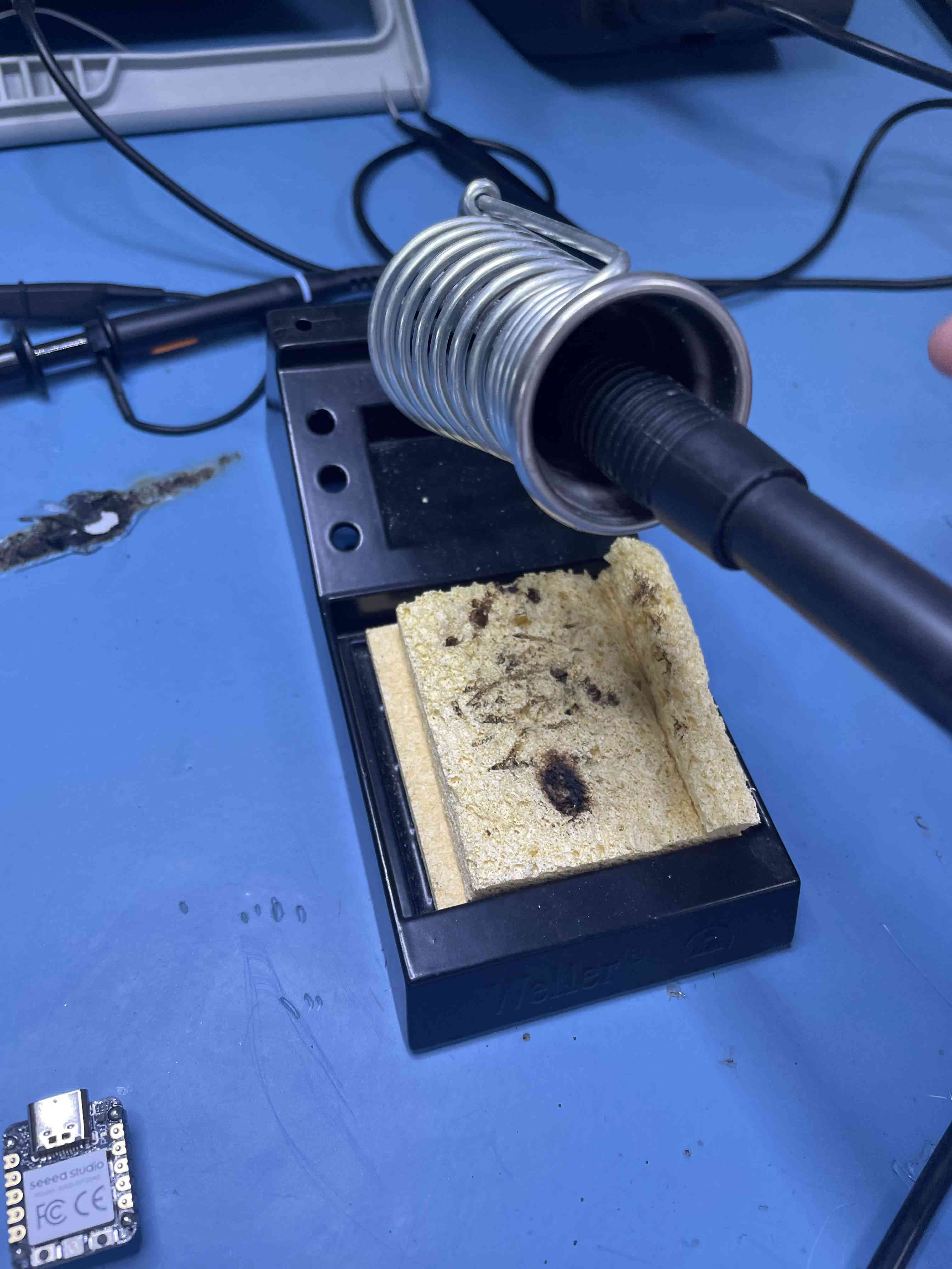
Step 3: heat the solder head
Step 4: clear the solder head
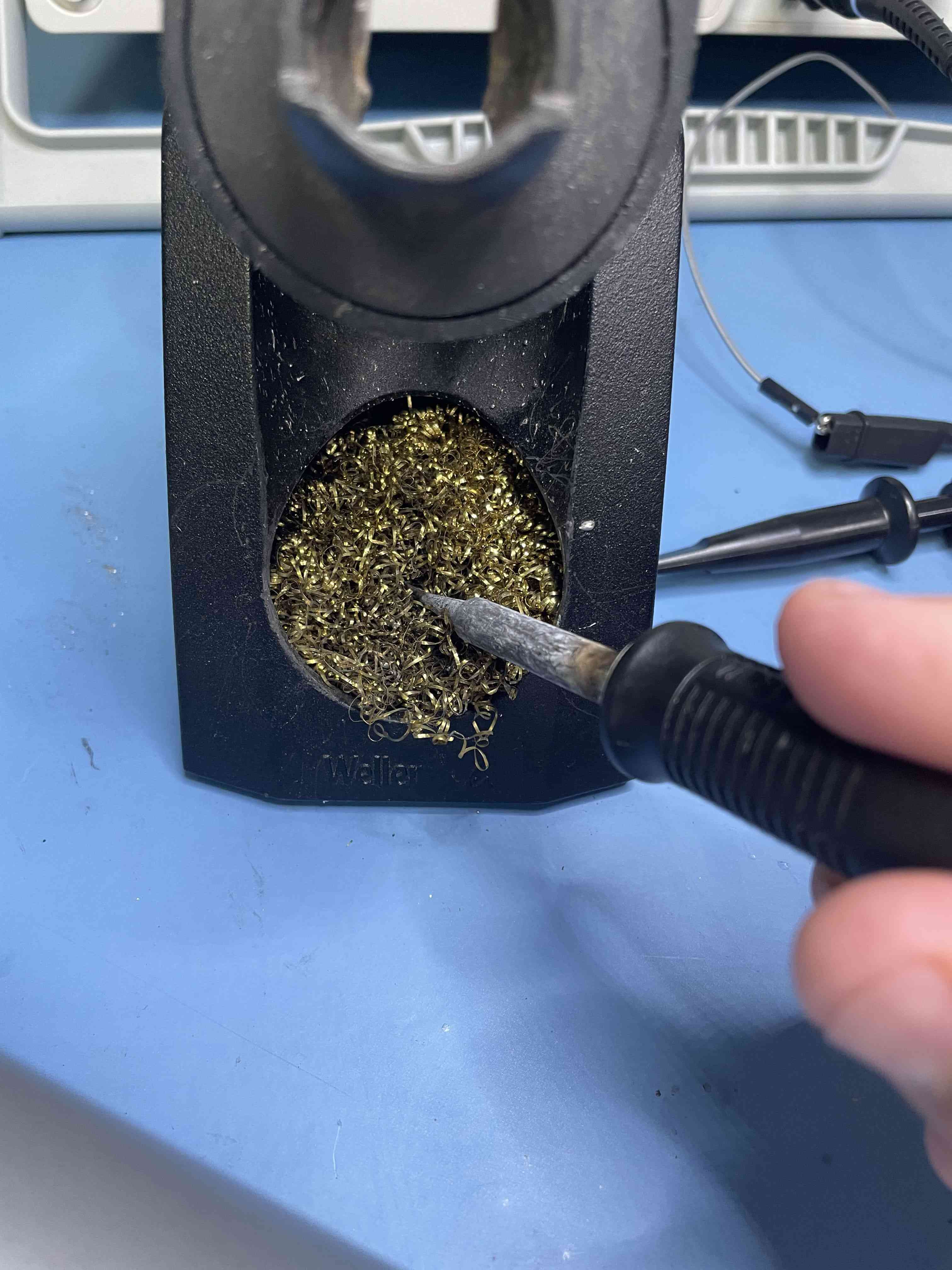
Step 5: have a clean environment and turn on the air cleaner (vacuum)
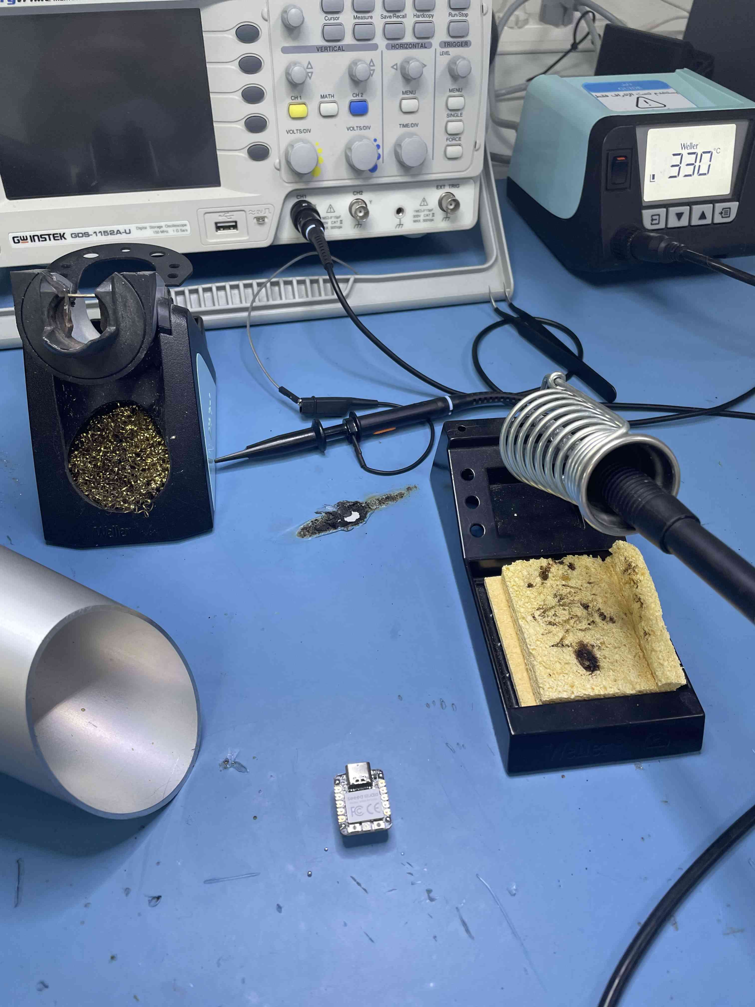
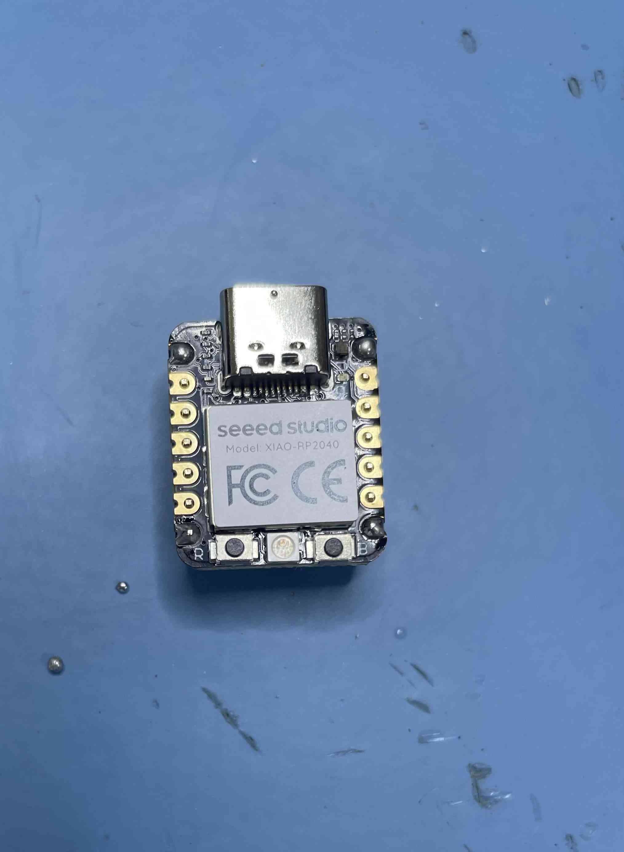
Step 6: final result
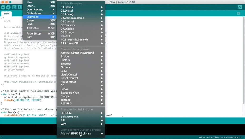
Step 1. Download and Install the latest version of Arduino IDE according to your operating system

Step 2. Launch the Arduino application.
Step 3. Add Seeed Studio XIAO RP2040 board package to your Arduino IDE.
Navigate to File > Preferences, and fill Additional Boards Manager URLs with the url below:
https://github.com/earlephilhower/arduino-pico/releases/download/global/package_rp2040_index.json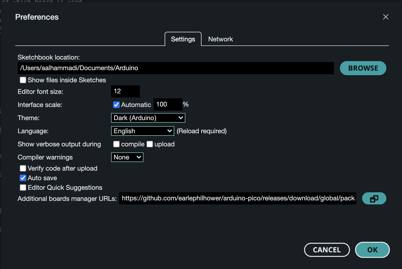
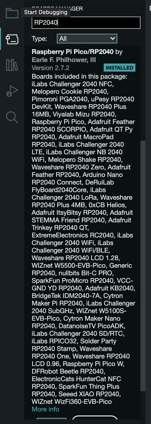
Step 4. Navigate to Tools-> Board-> Boards Manager..., type the keyword "RP2040" in the searching blank. Select the lastest version of "Raspberry Pi Pico/RP2040" and install it.
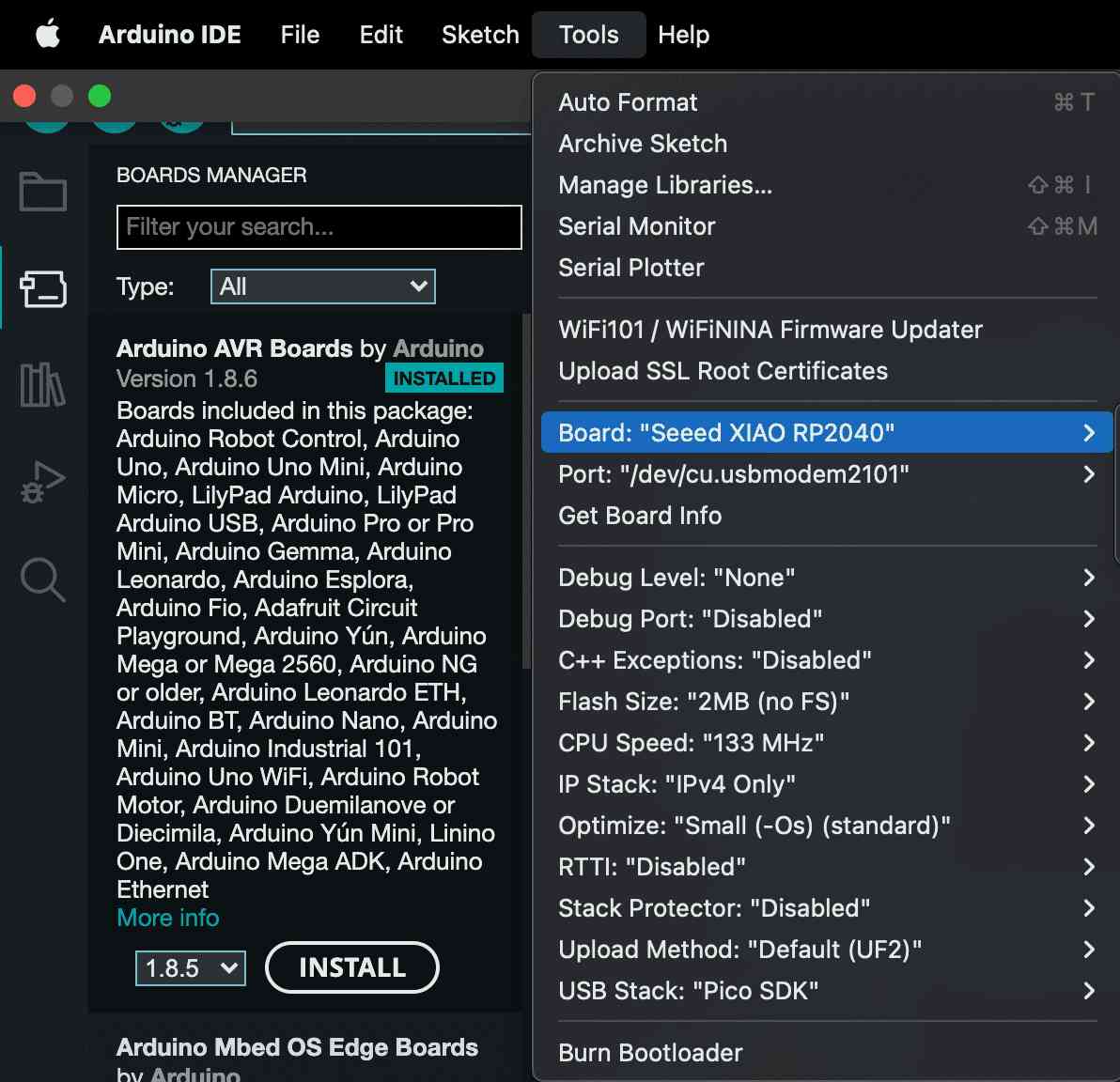
Step 5. Select your board and port.
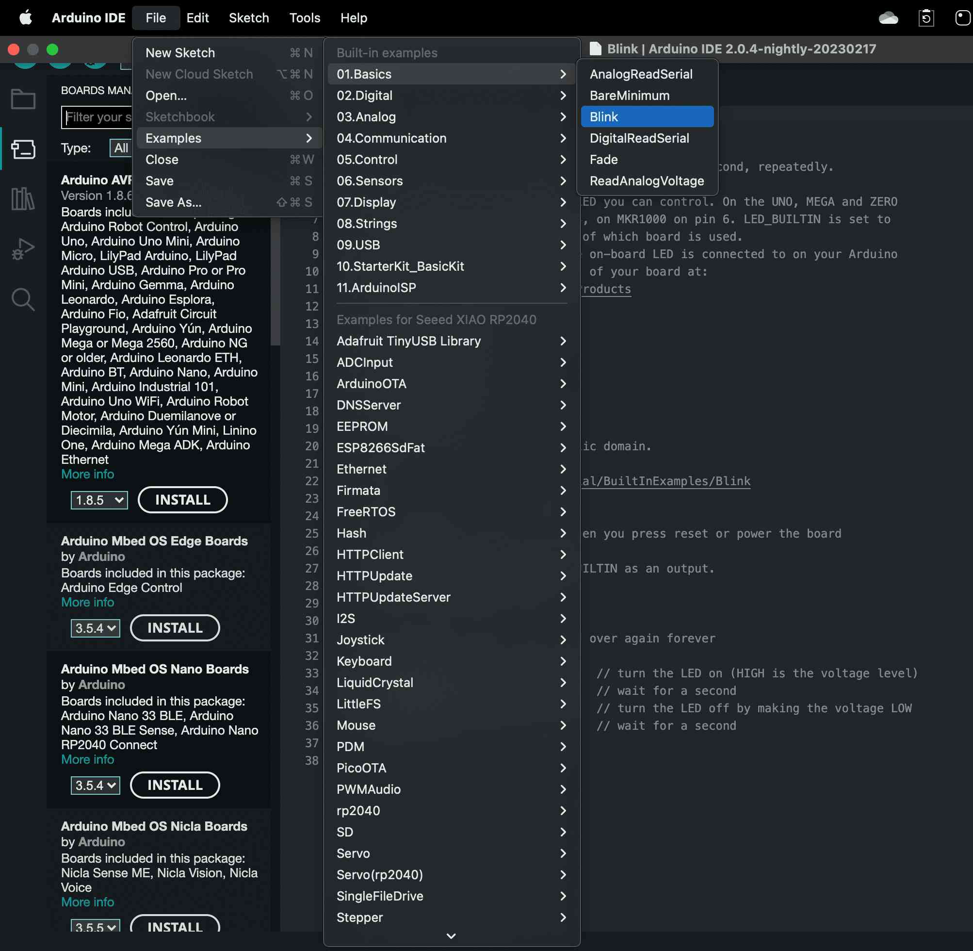
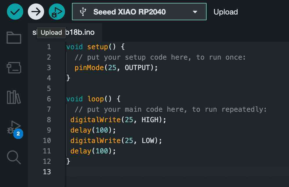
Step 6. Open the Blink example by navigating "File → Examples --->01.Basics → Blink".
void setup() {
    // put your setup code here, to run once:
    pinMode (25, OUTPUT) ;
}

void loop() {
    // put your main code here, to run repeatedly:
    digitalWrite(25, HIGH) ;
    delay (1000);
    digitalWrite(25, LOW) ;
    delay(1000);
}Upload the code to the board --> here I just change the delay to (100)ms to speed up the blinking
#define ledPin = 9;      // Pin connected to the LED
#define potPin = A0;     // Pin connected to the potentiometer
int brightness = 0;        // Variable to store the brightness value

void setup() {
  pinMode(ledPin, OUTPUT); // Set the LED pin as an output
}

void loop() {
  brightness = analogRead(potPin);   // Read the potentiometer value
  brightness = map(brightness, 0, 1023, 0, 255); // Map the value to a range between 0 and 255
  analogWrite(ledPin, brightness);   // Set the LED brightness using PWM
}#define Red 28
#define Yallow 27
#define Green 26
void setup() {
// put your setup code here, to run once:
pinMode(Green, OUTPUT);
pinMode(Yallow, OUTPUT) ;
pinMode(Red, OUTPUT);
}
void loop() {
// case 1: Green on
digitalWrite (Green, HIGH);
delay (500); // delay is 500 ms
digitalWrite (Green, LOW);
// case 2: Yallow on
digitalWrite(Yallow, HIGH) ;
delay (500); // delay is 500 ms
digitalWrite(Yallow, LOW) ;
// case 3: Red on
digitalWrite(Red, HIGH) ;
delay (500) ; // delay is 500 ms
digitalWrite(Red, LOW);
}#define Red 28
#define Yallow 27
#define Green 26
#define BUTTON 29
void setup() {
// put your setup code here, to run once:
pinMode(Green, OUTPUT);
pinMode (Yallow, OUTPUT) ;
pinMode (Red, OUTPUT);
pinMode (BUTTON, INPUT PULLUP);
}
void loop() {
byte buttonState = digitalRead (BUTTON) ;
if (buttonState == LOW) {
// case 1: Green on
digitalWrite(Green, HIGH);
delay (500);
digitalWrite(Green, LOW);
// case 2: Yallow on
digitalWrite(Yallow, HIGH) ;
delay (500);
digitalWrite(Yallow, LOW);
// case 3: Redl on
digitalWrite(Red, HIGH);
delay (500);
digitalWrite(Red, LOW);
}else {
digitalWrite(Green, LOW);
digitalWrite(Yallow, LOW) ;
digitalWrite(Red, LOW);
}#define Red 28
#define Yallow 27
#define Green 26
#define BUTTON 29
int d;
void setup() {
// put your setup code here, to run once:
pinMode(Green, OUTPUT);
pinMode(Yallow, OUTPUT);
pinMode(Red, OUTPUT);
pinMode(BUTTON, INPUT_PULLUP);
}
void loop() {
byte buttonState = digitalRead(BUTTON);
if (buttonState == HIGH){
d= 500;
}else {
d = 100;
}
digitalWrite(Green, HIGH);
delay(d);
digitalWrite(Green, LOW);
// case 2: Yallow on
digitalWrite(Yallow, HIGH);
delay(d);
digitalWrite(Yallow, LOW);
// case 3: Red on
digitalWrite(Red, HIGH);
delay(d);
digitalWrite(Red, LOW);
}
const int photoresistorPin = A0;
const int ledPin = 27;

void setup() {
  pinMode(ledPin, OUTPUT);
  Serial.begin(9600);
}

void loop() {
  int lightLevel = analogRead(photoresistorPin);
  Serial.print("Light level: ");
  Serial.println(lightLevel);

  if (lightLevel < 50){
    digitalWrite(ledPin, HIGH);
  } else {
    digitalWrite(ledPin, LOW);
  }

  delay(1000);
}
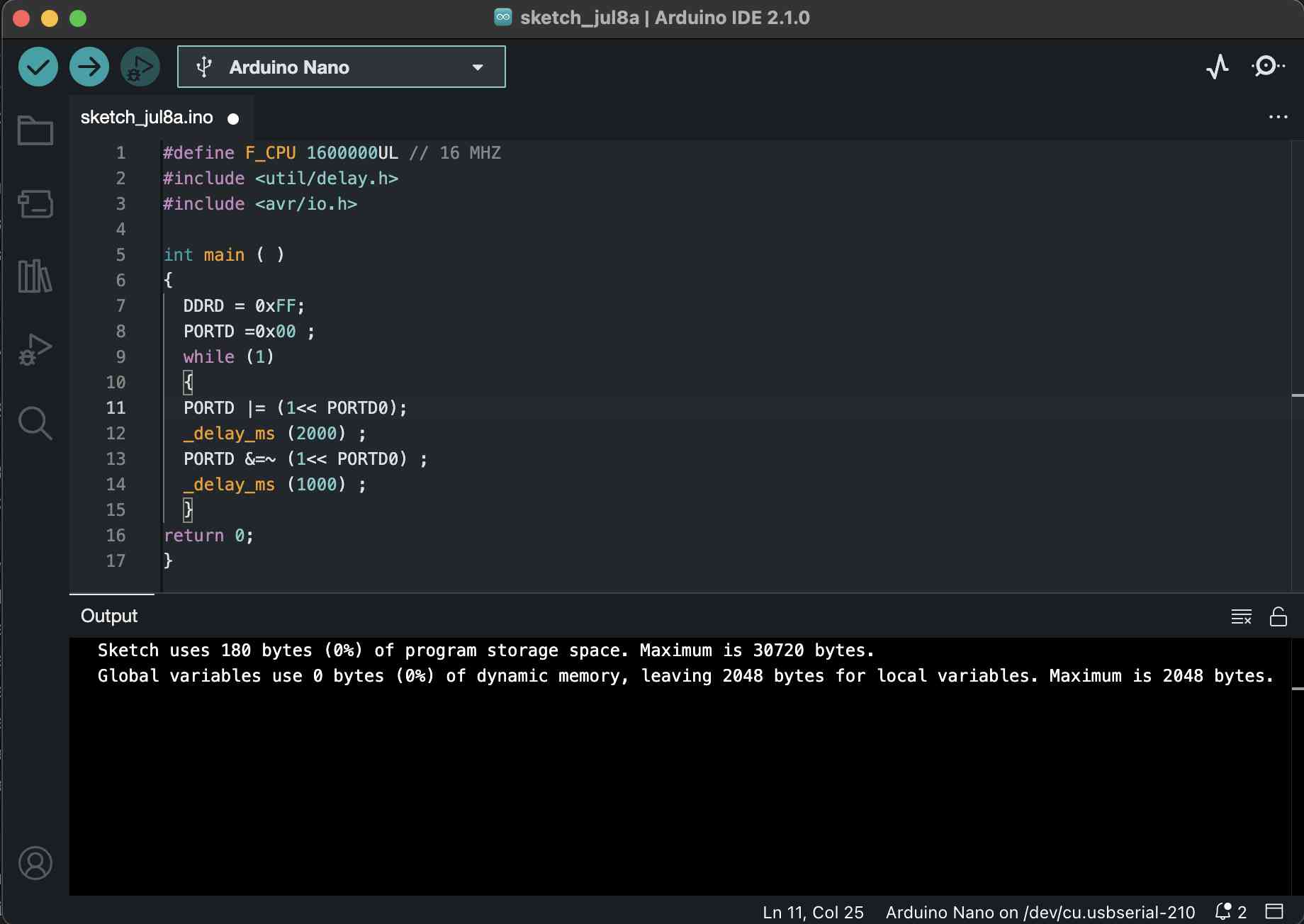
#define F_CPU 1600000UL // 16 MHZ
#include
#include

int main ( )
{
  DDRD = 0xFF;
  PORTD =0x00 ;
	while (1)
	{
	PORTD |= (1<< PORTD0);
	_delay_ms (2000) ;
	PORTD &=~ (1<< PORTD0) ;
	_delay_ms (1000) ;
	}
return 0;
}
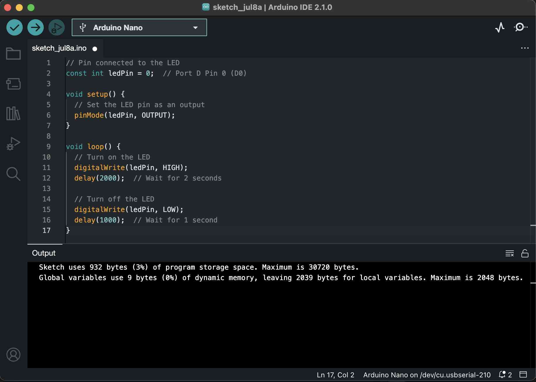
// Pin connected to the LED
const int ledPin = 0;  // Port D Pin 0 (D0)

void setup() {
  // Set the LED pin as an output
  pinMode(ledPin, OUTPUT);
}

void loop() {
  // Turn on the LED
  digitalWrite(ledPin, HIGH);
  delay(2000);  // Wait for 2 seconds

  // Turn off the LED
  digitalWrite(ledPin, LOW);
  delay(1000);  // Wait for 1 second
}
As we can see the the images below there are difference in the size so we can say the "C" is smaller in size so it is faster in compiling but harder in coding than "C++"
For this project:
C = 180 bytes
C++ = 932 bytes