
.jpeg)
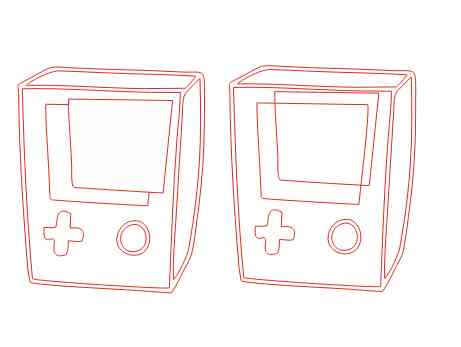
Design a parametric press fit construction kit and cut it using laser cutting machine.
Cut/Print sticker using Vinyl Cutter machine.

.jpeg)

In this week the aim was to be familiar with all cutting machines available in the lab to be able to implement 2D and 3D designs.
Press fit: is the fastening of two parts that is achieved by normal force, friction and cold welding.
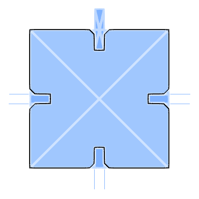
In beginning, I decided to design one shape consisting of a cube that we can connect 2 or more pieces to form shapes.
For the press fit 3D model I use "Autodesk Fusion" and I record all the steps in one video to explain everything
1- 3D model for the Press fit Kit
2- Video (3D model design)
Used material in this task was “Cardboard” which not expensive and easy to find.
The used machine was "Universal Laser systems", I did use the cutting setting shown below.
1- Manual control Red color for Cutting:
Power : 100%
Speed: 10.0%
PPI: 200
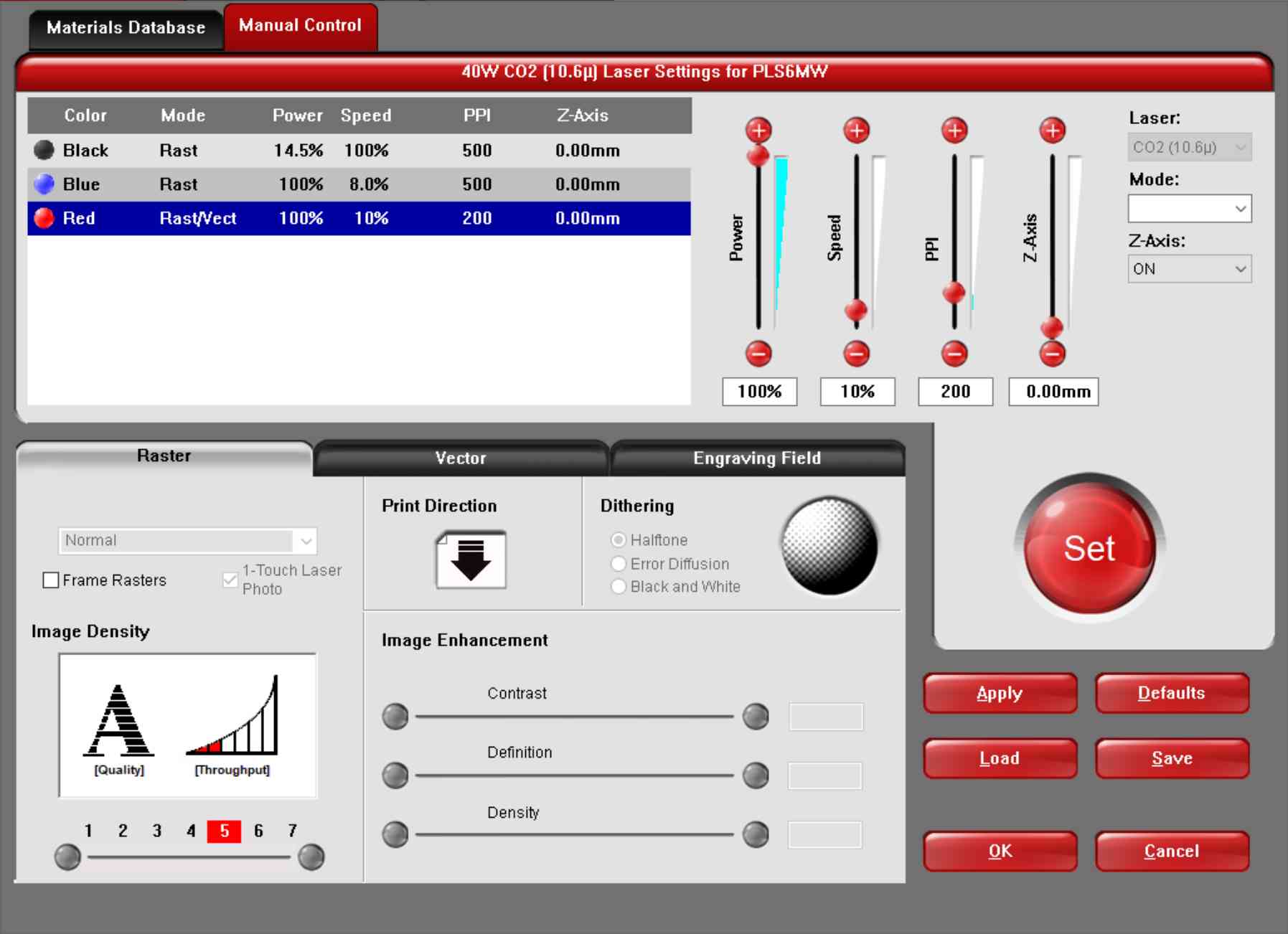
2- Select the Materials from the Materials Database
3- Select all the lines you want to cut in Red color
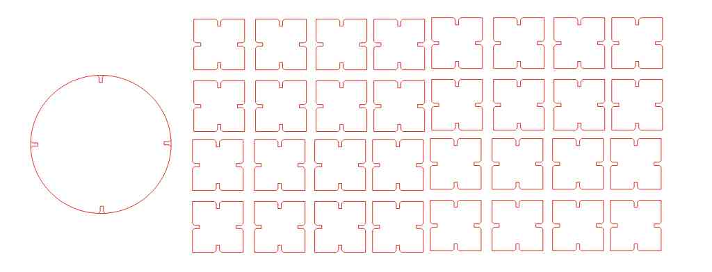
4- Point the laser Head to the correct place after selecting this field

5- Then follow the steps mentioned above to transfer the object to the laser points
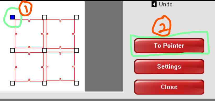
6- Open the filter and then start cutting with the laser machine and watch it carefully to avoid any possible mistake
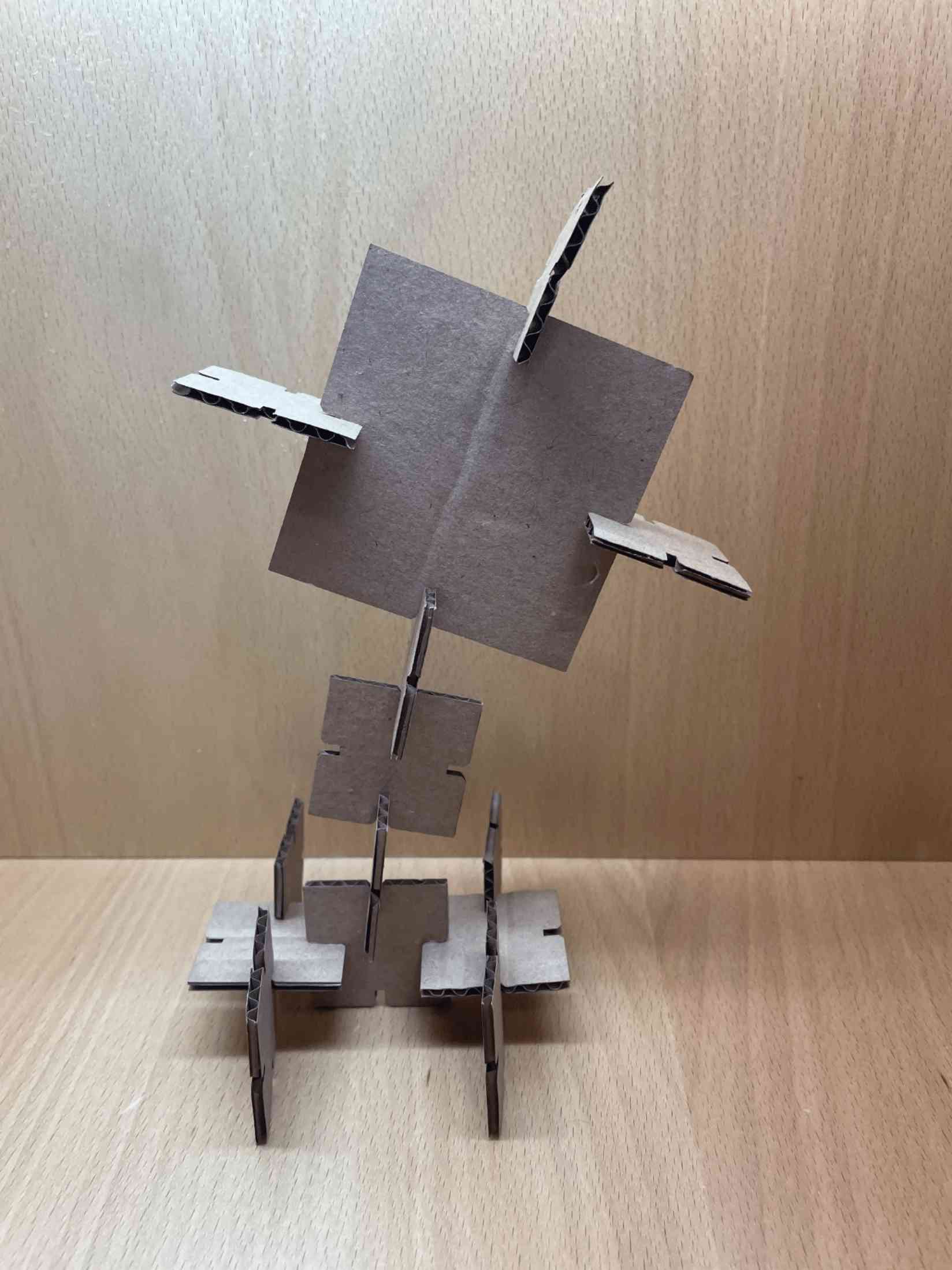
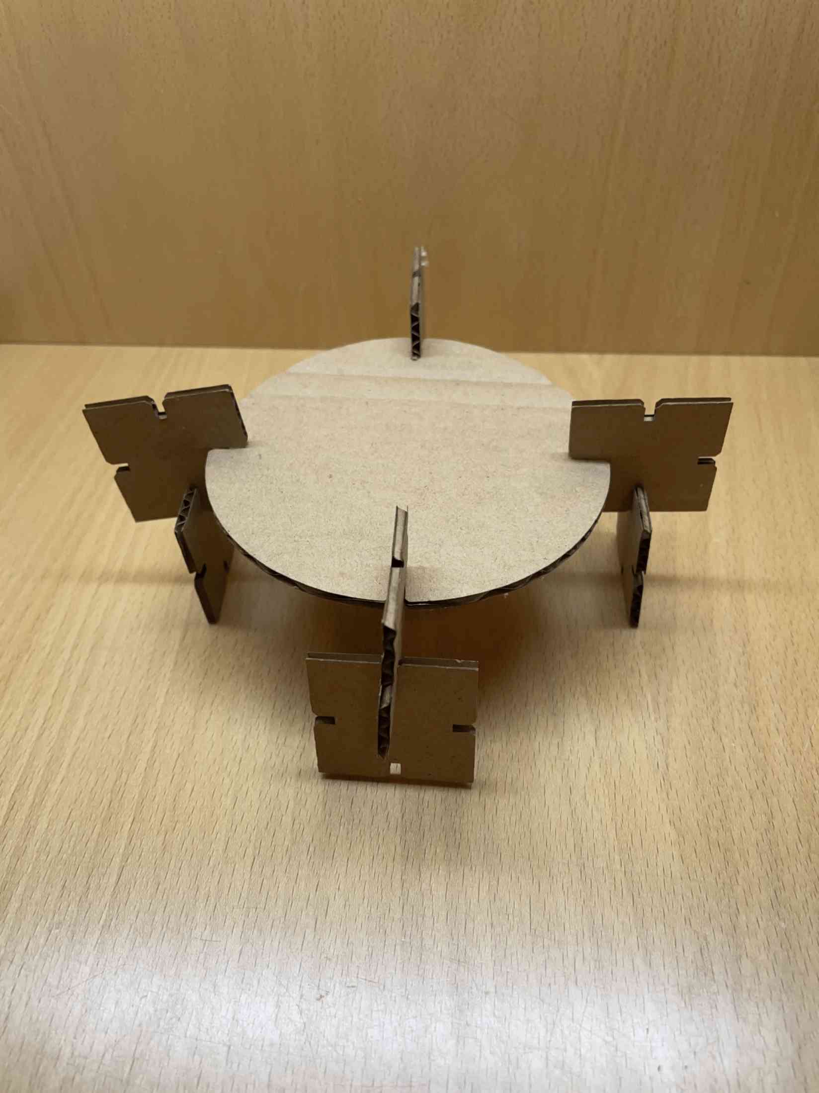
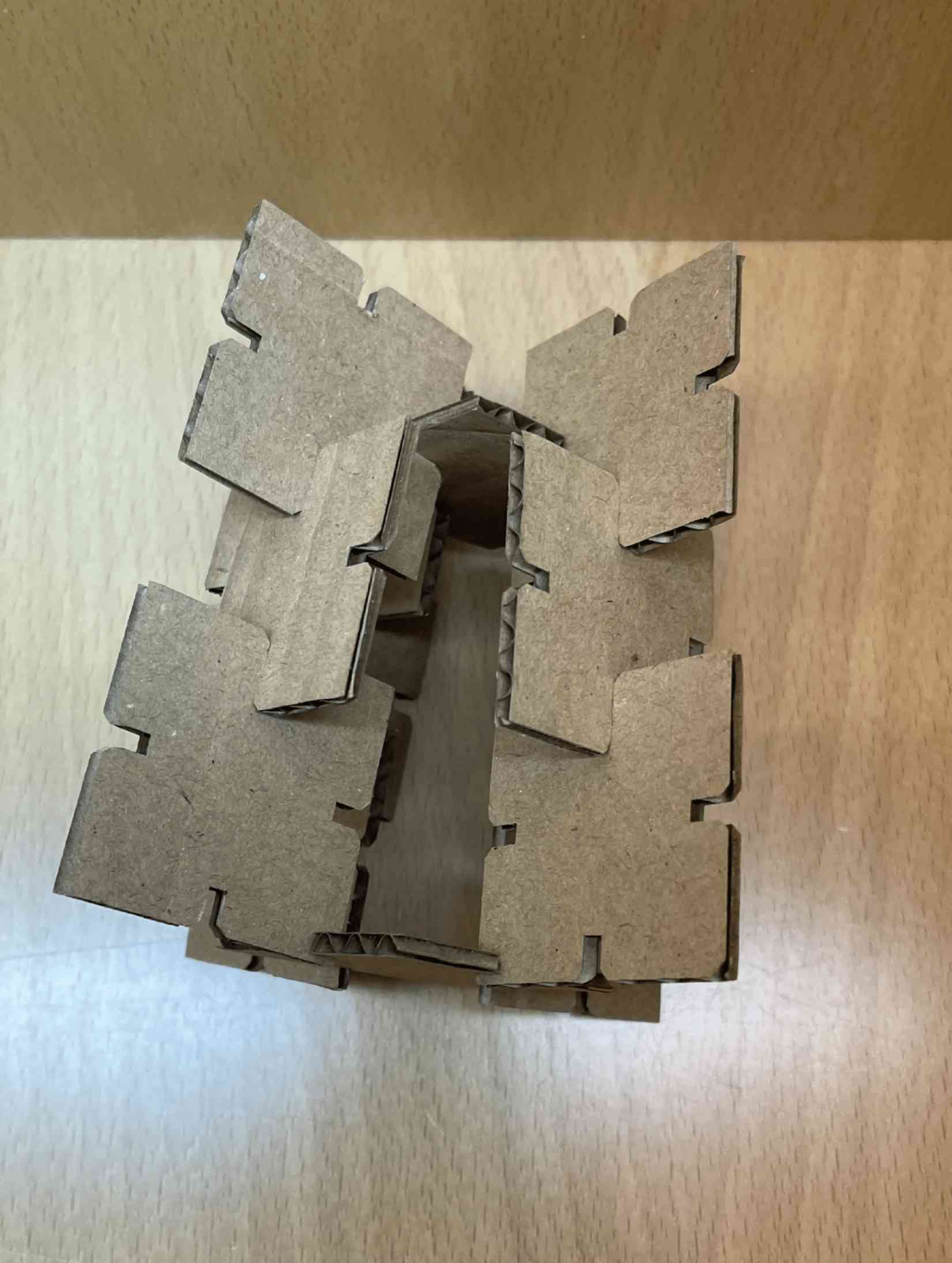
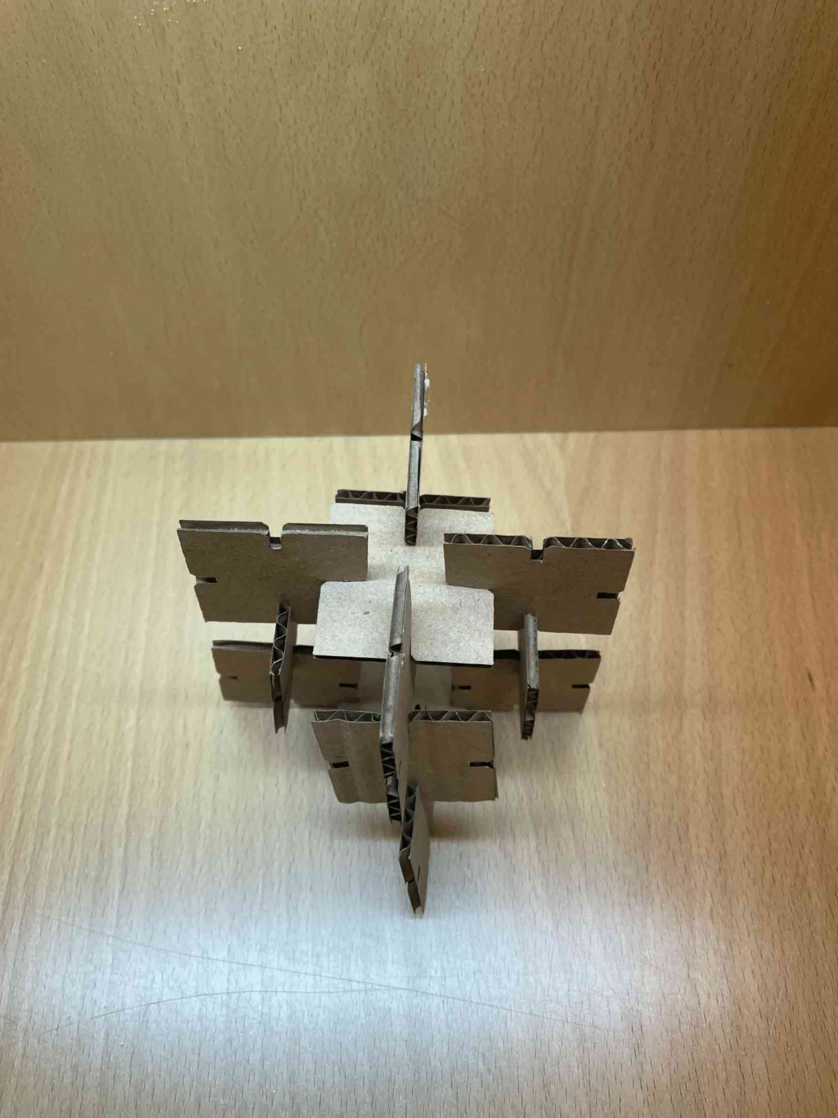
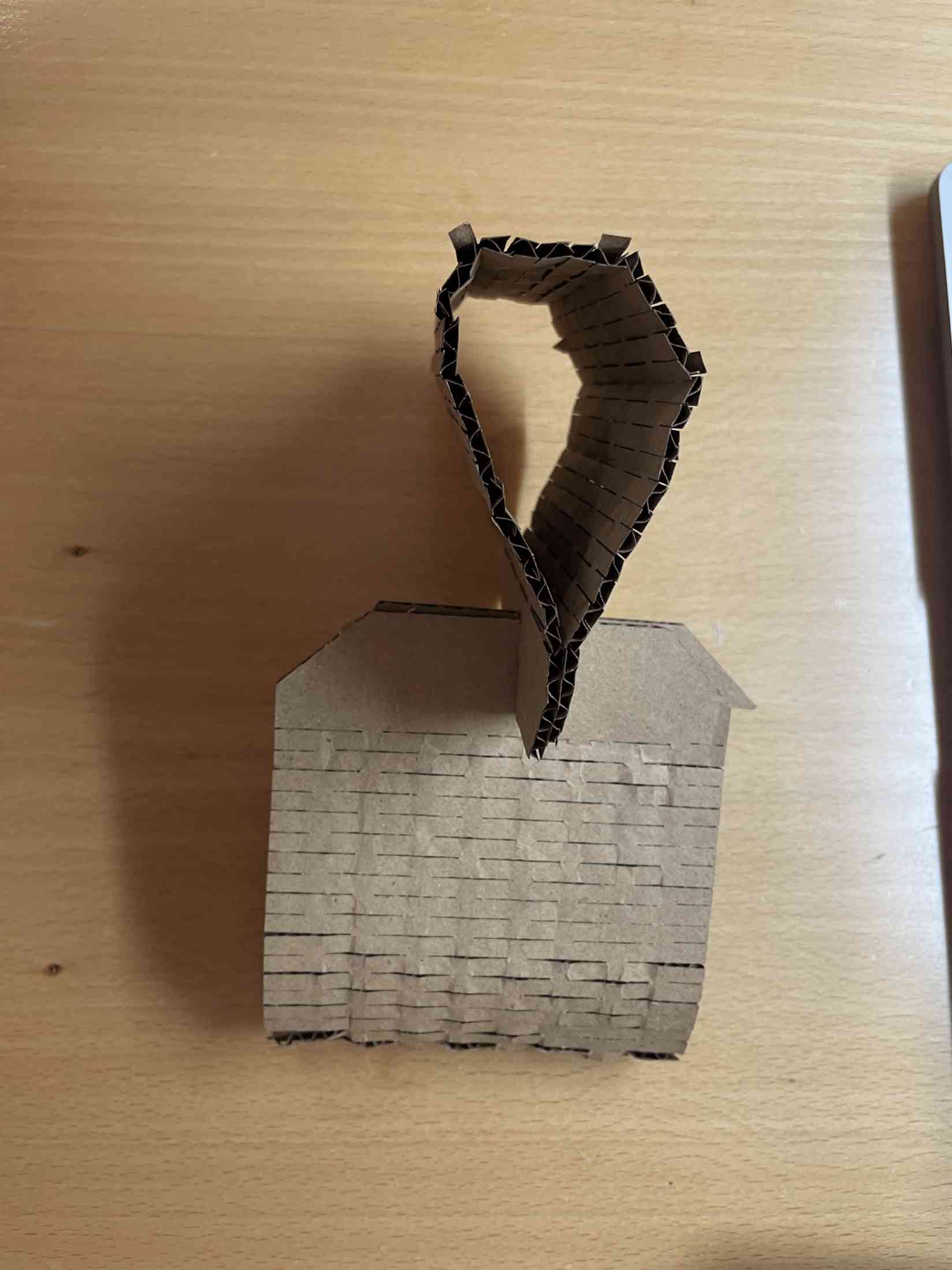
- I discovered that there were some errors in the design, so the pieces did not fit in a good way, so I made adjustments in the measurements 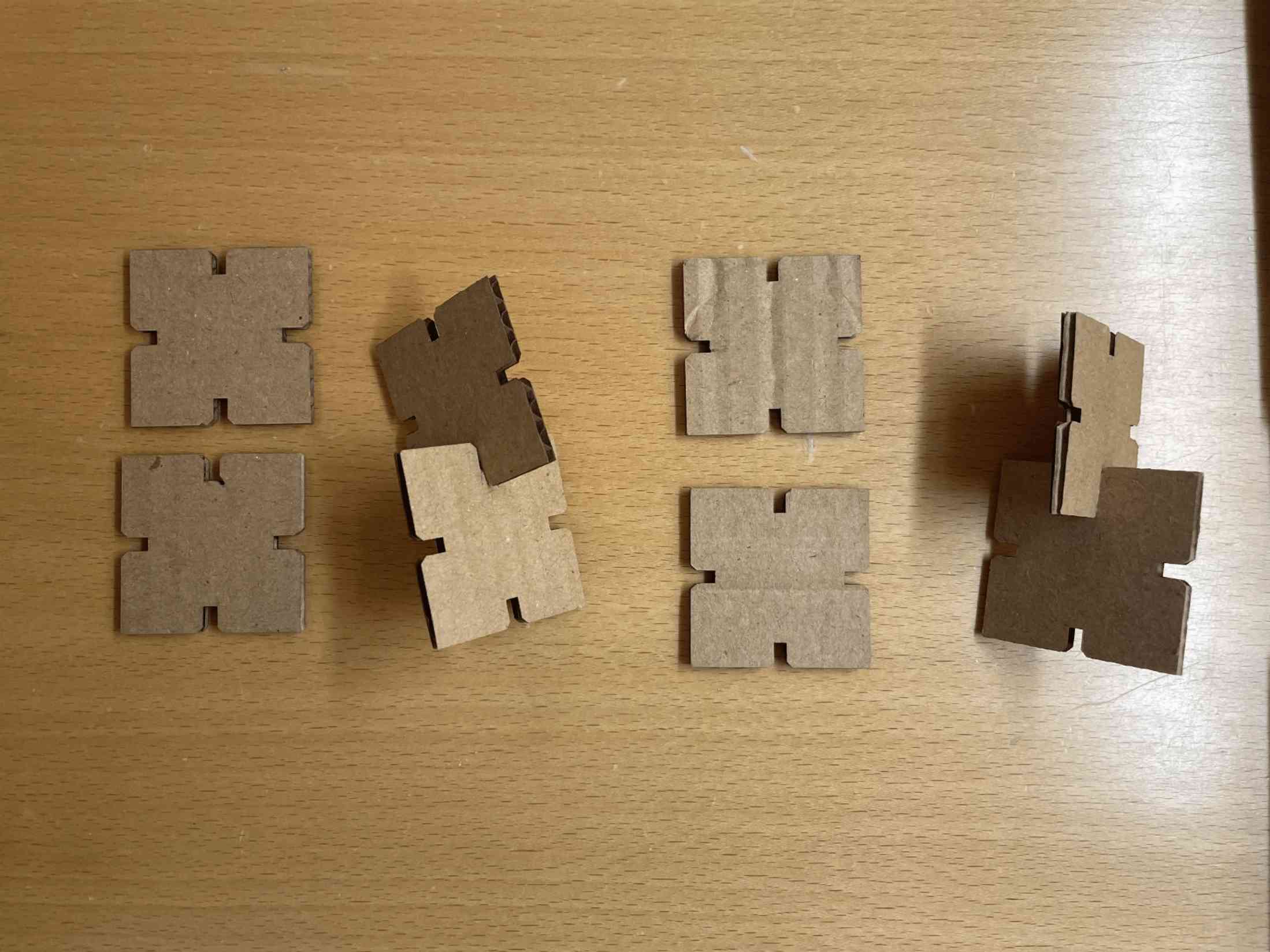
- I discovered that I forgot one of the red lines in side the object, so the laser cutter cut it off
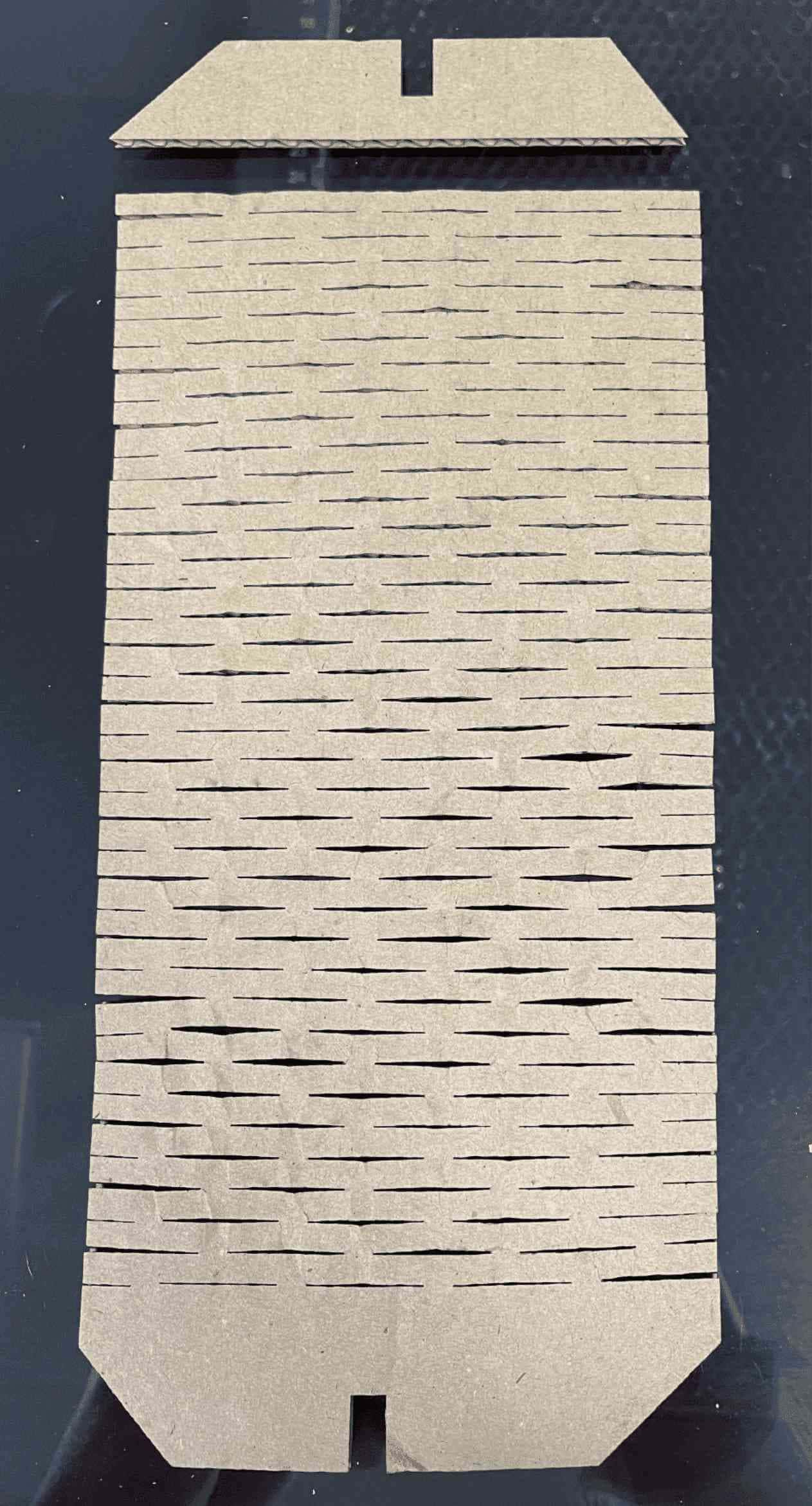
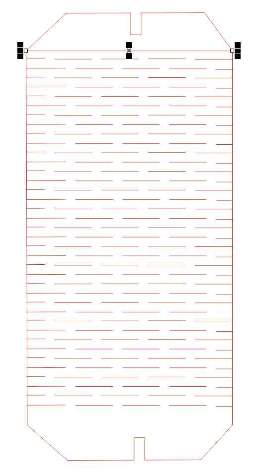
- Wrong orientation 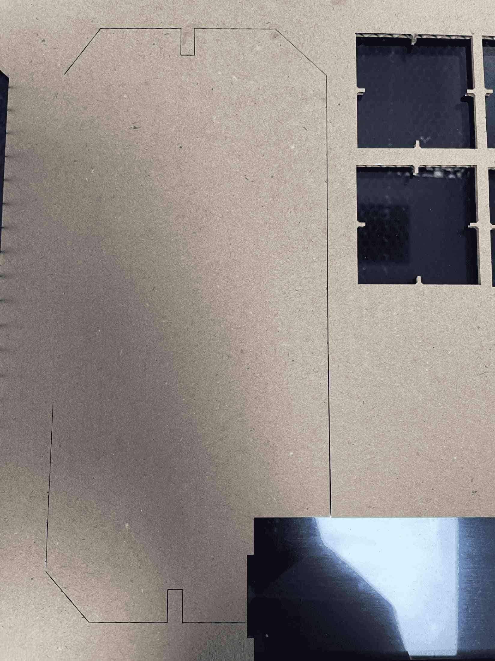
The Kerf value for the laser cutter, how dithering functions, and the distinctions between various forms of dithering are some of the things we discovered through the group project that I will undoubtedly utilize in the future. To guarantee that the dimensions are identical to or at least close to how you want them to be after cutting your item, the kerf value just has to be applied to each pertinent dimension.
First I did start by using Roland vinyl Cutter I download this image from google and I will use it for this task

Afterward, I did open corelDRAW and follow the mention steps below:
Create new file.
Upload the logo in corelDRAW.
Right click in logo and choose " Quick Trace" this separates the image and create vector that I need it for printing.
Left click “no color box”, then Right click “Red color box” to display the traces .
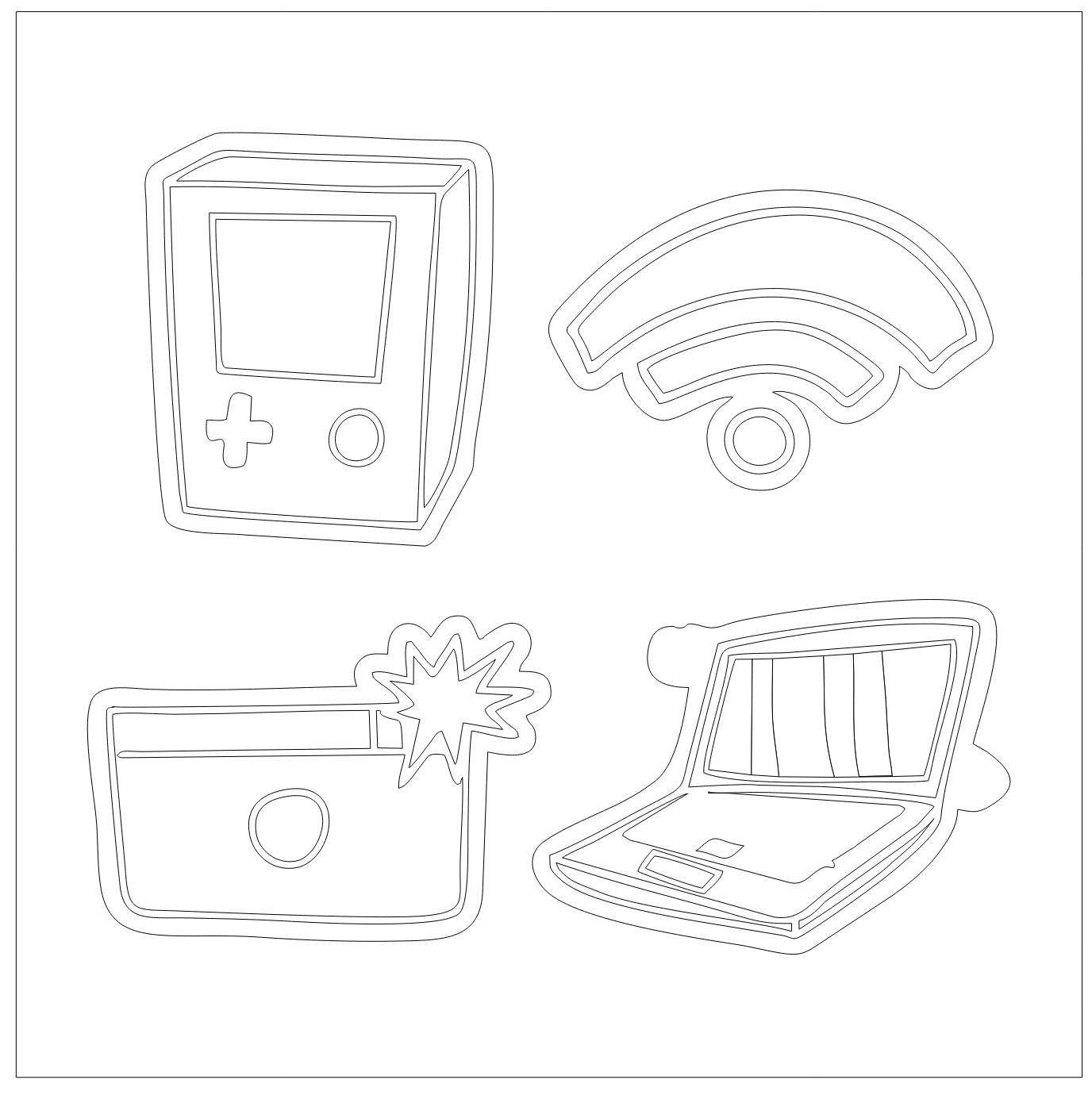
Before start printing and upload the logo in the Computer I did adjust the machine by putting the sticker roll. I did use black & Red color , then the cutter will calculate the width of the sheet that I will need after enter it in the software.
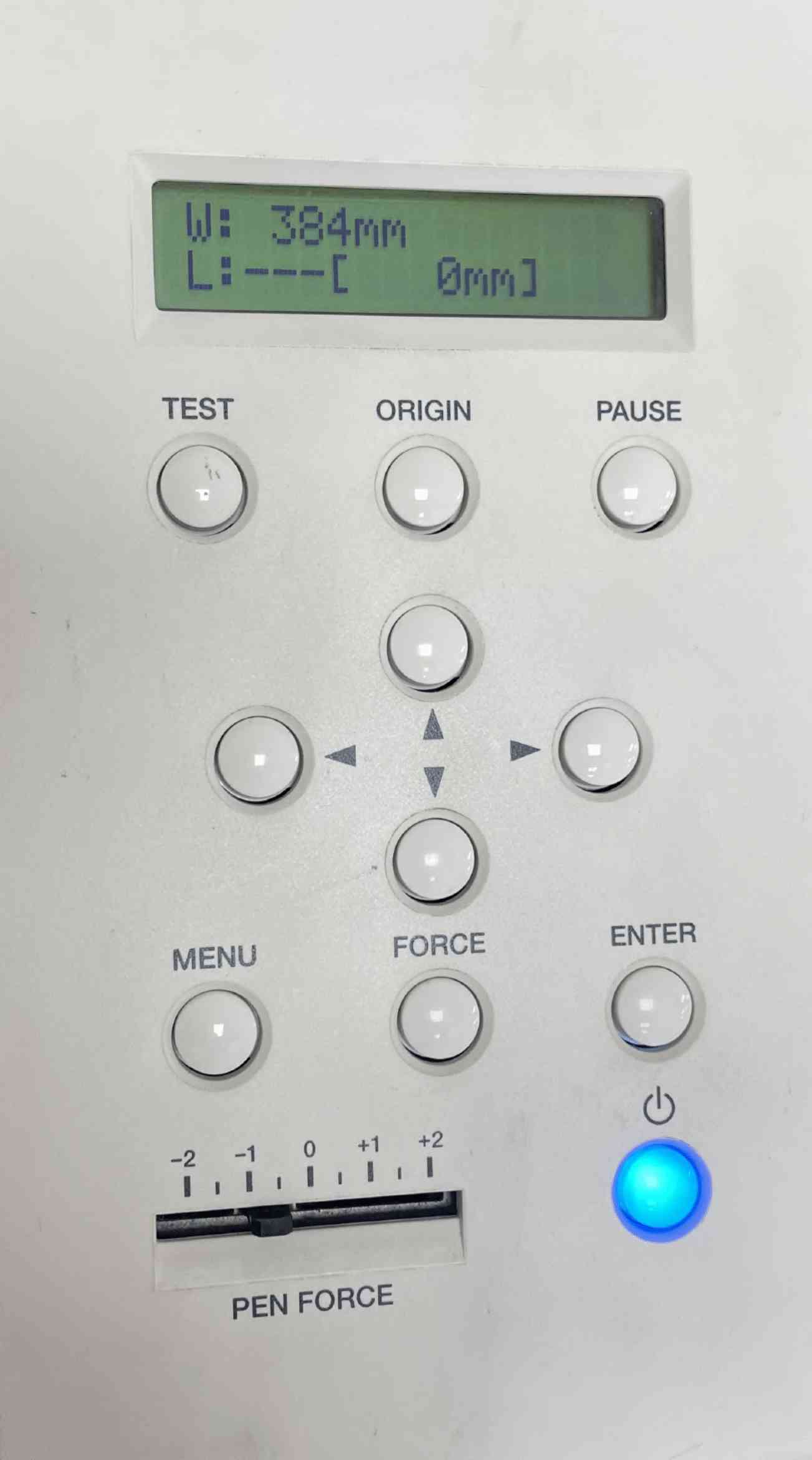
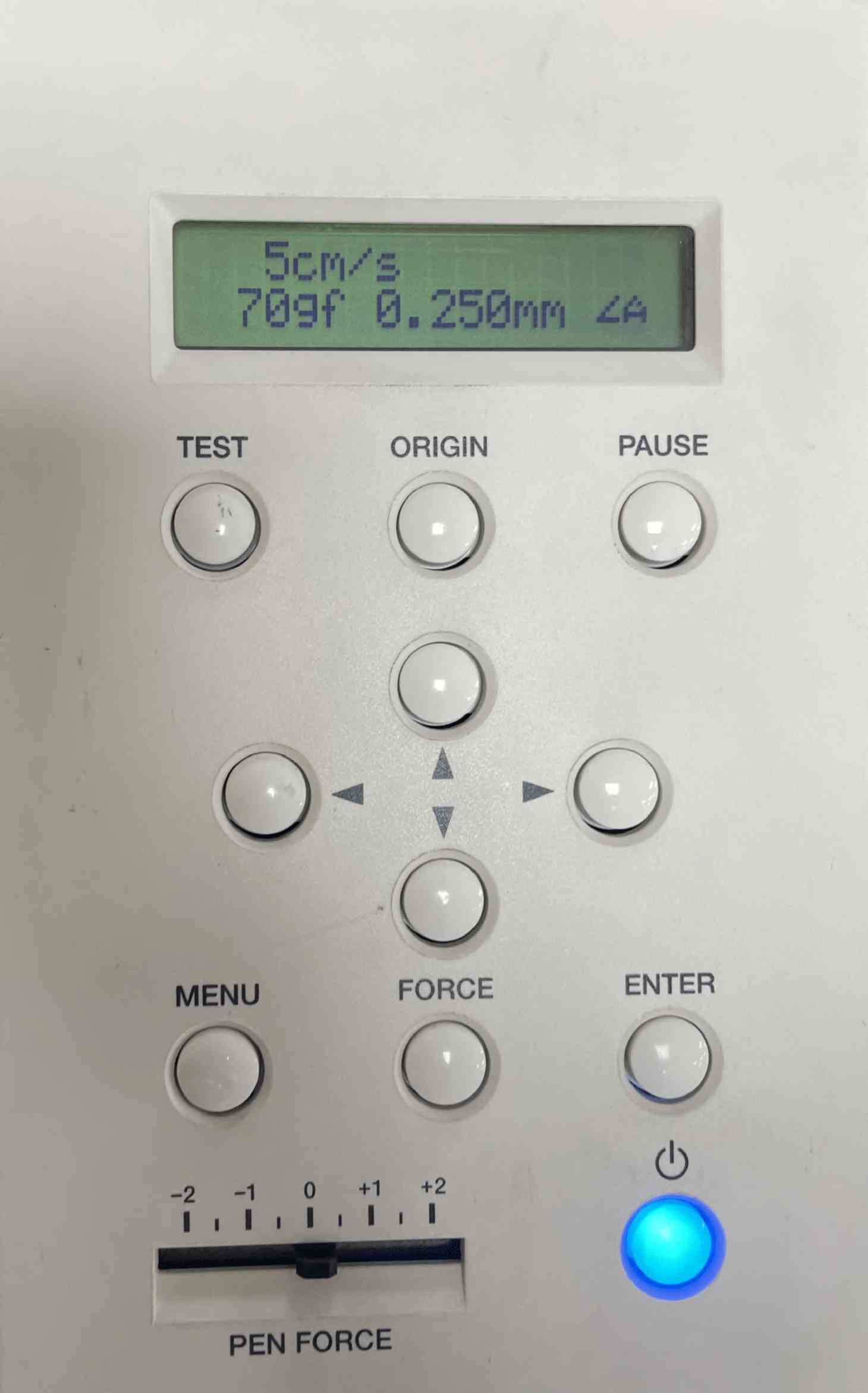
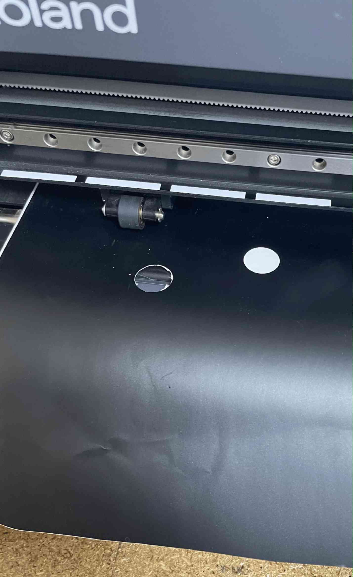
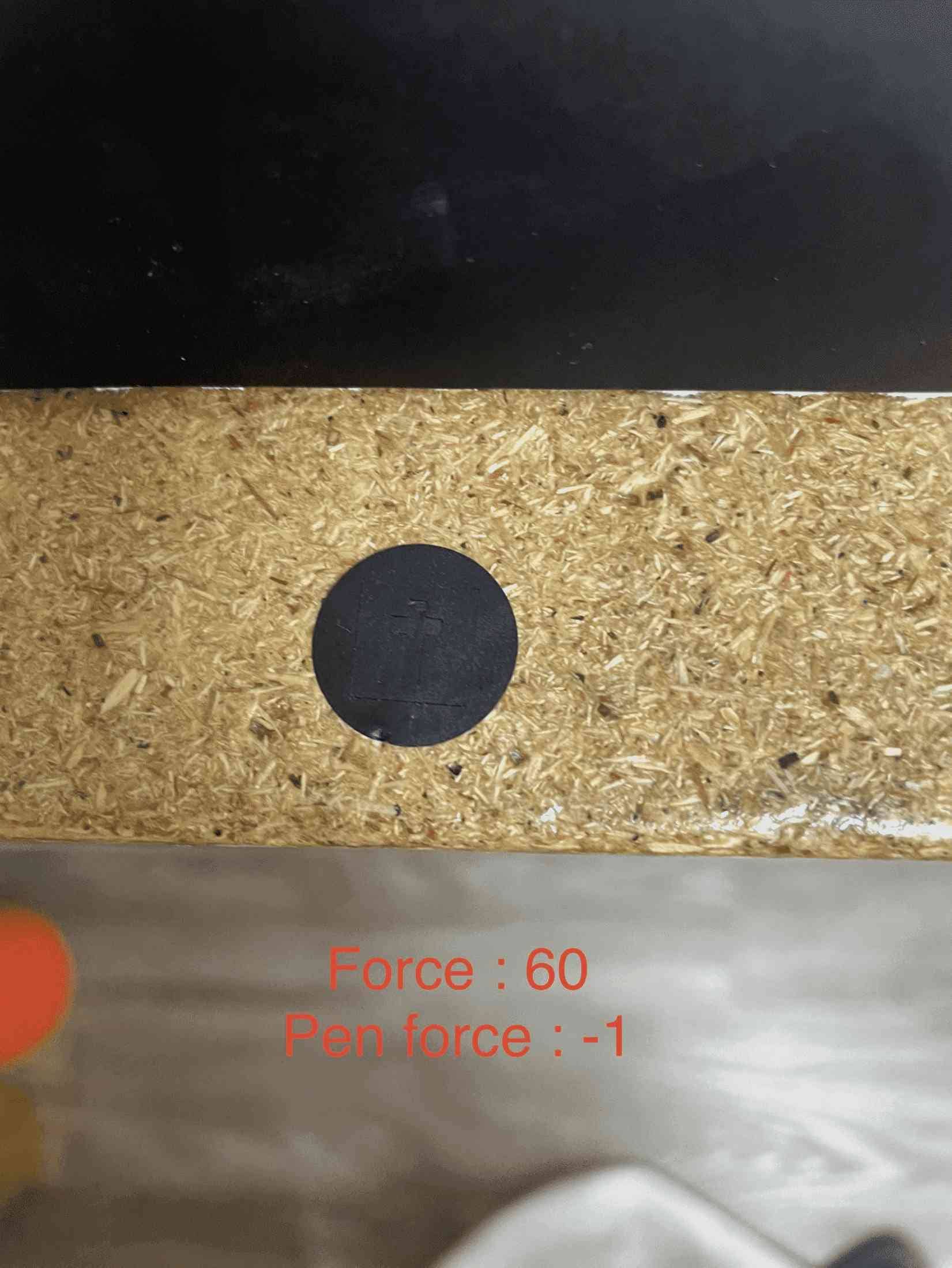
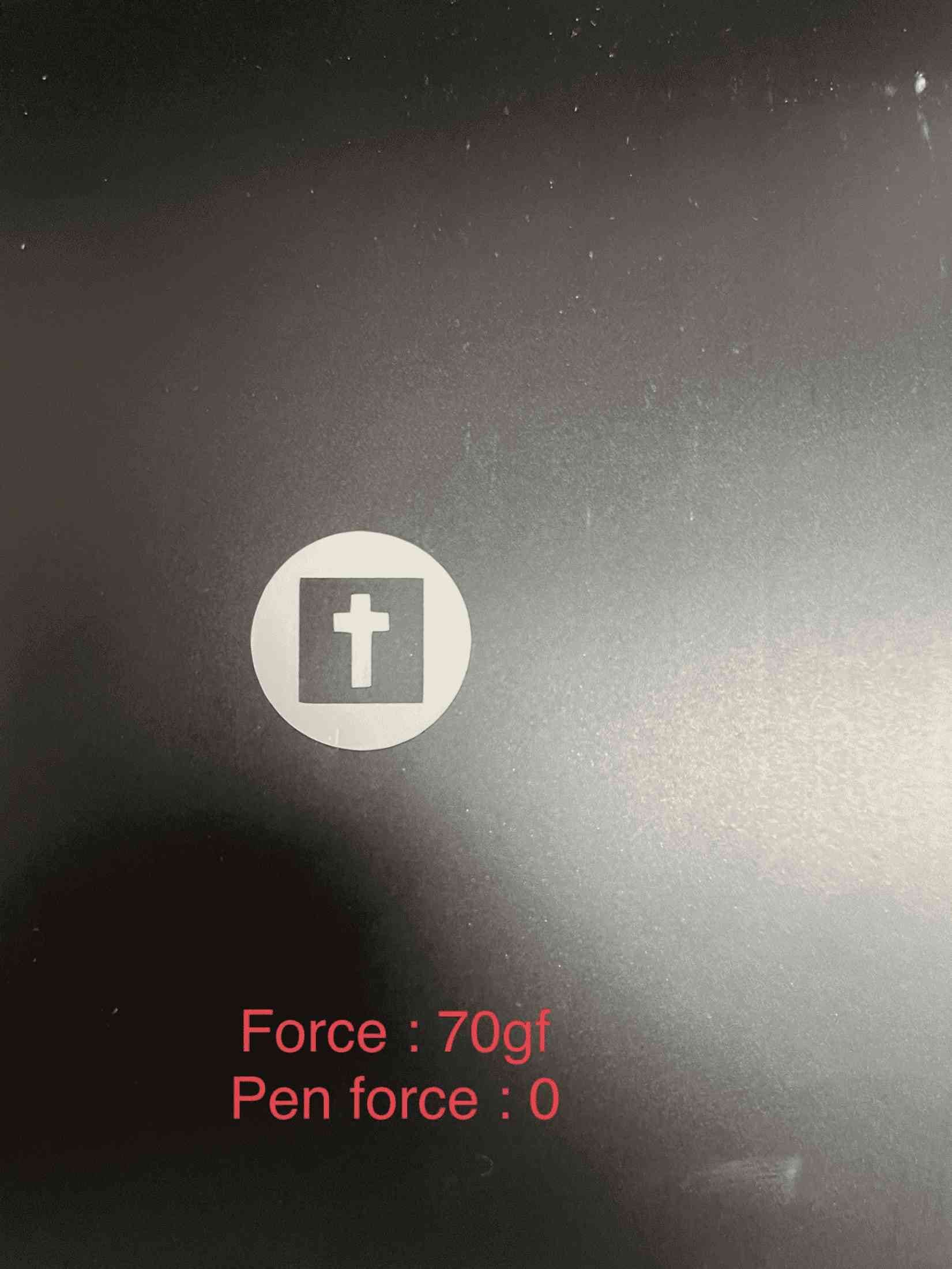
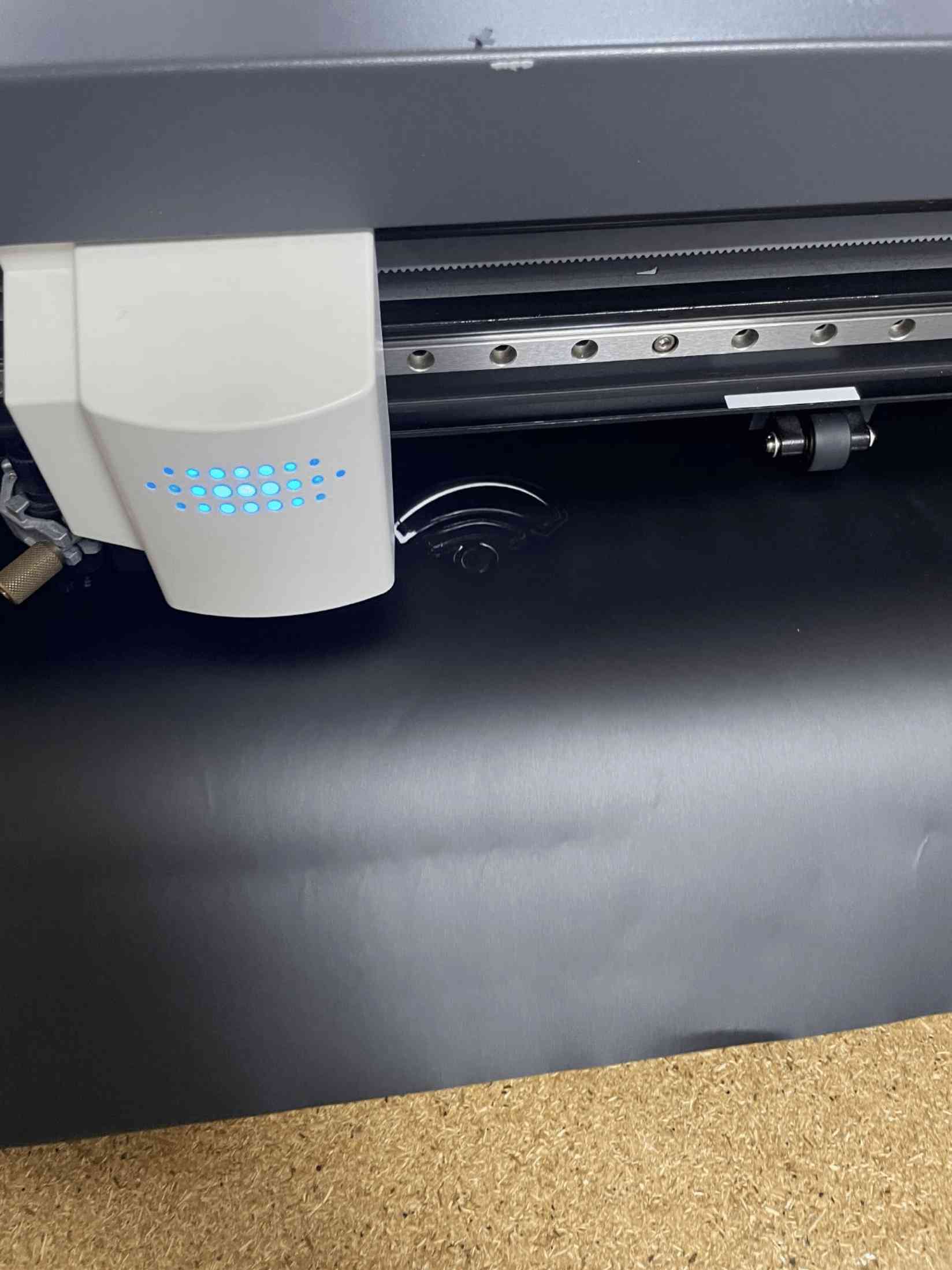
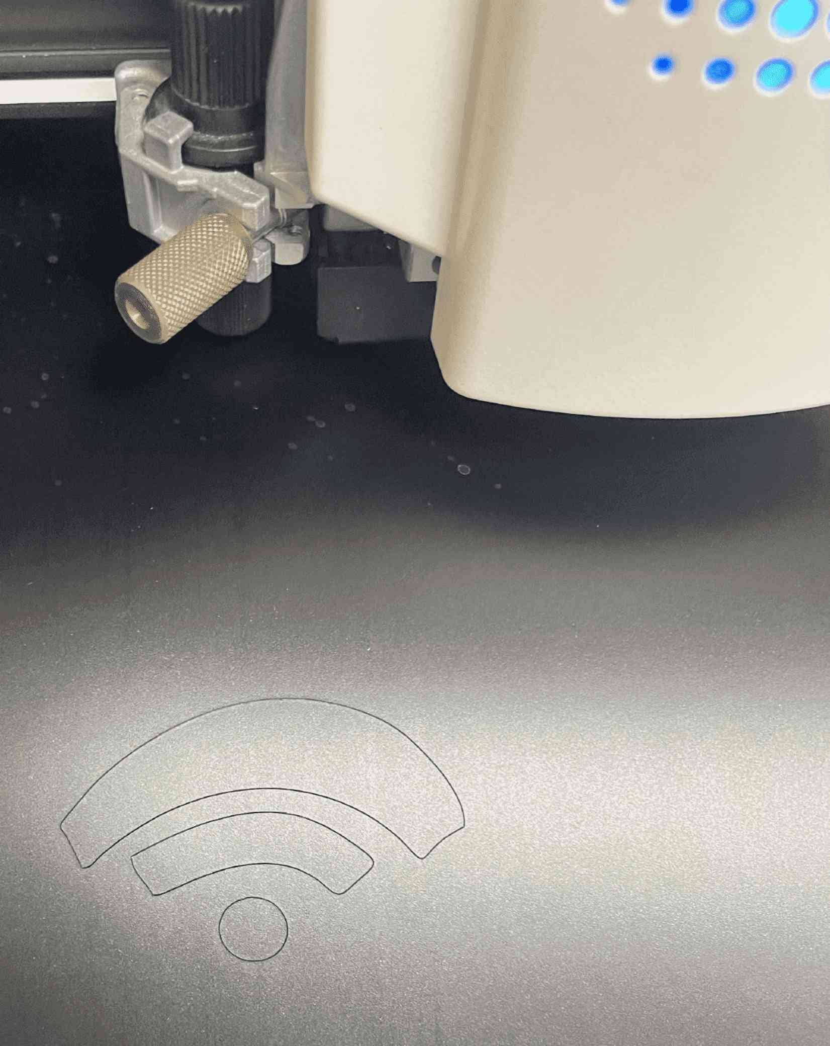
Moreover, I did test the force, I had found out the force give me the best cutting for the sheet is 70gf, the testing was done by keep pressing test button in the cutter and it will cut for me a sample to see if used force good or not as shown in images below.
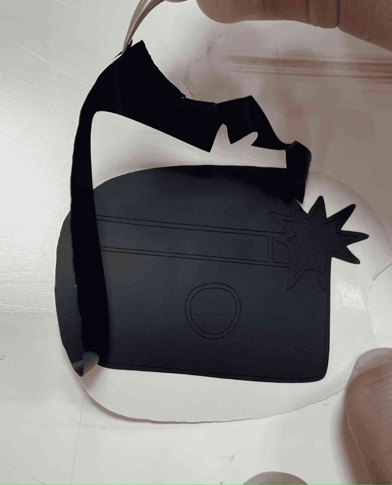
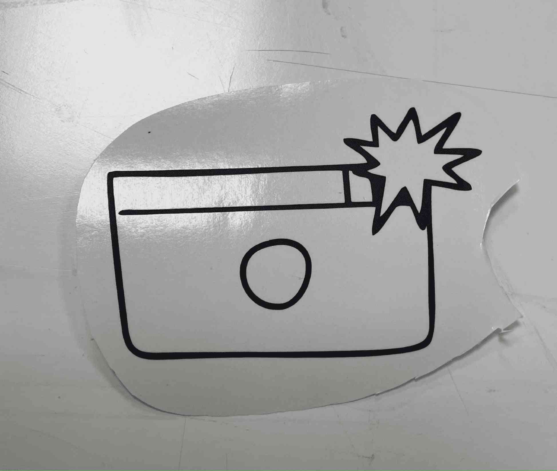
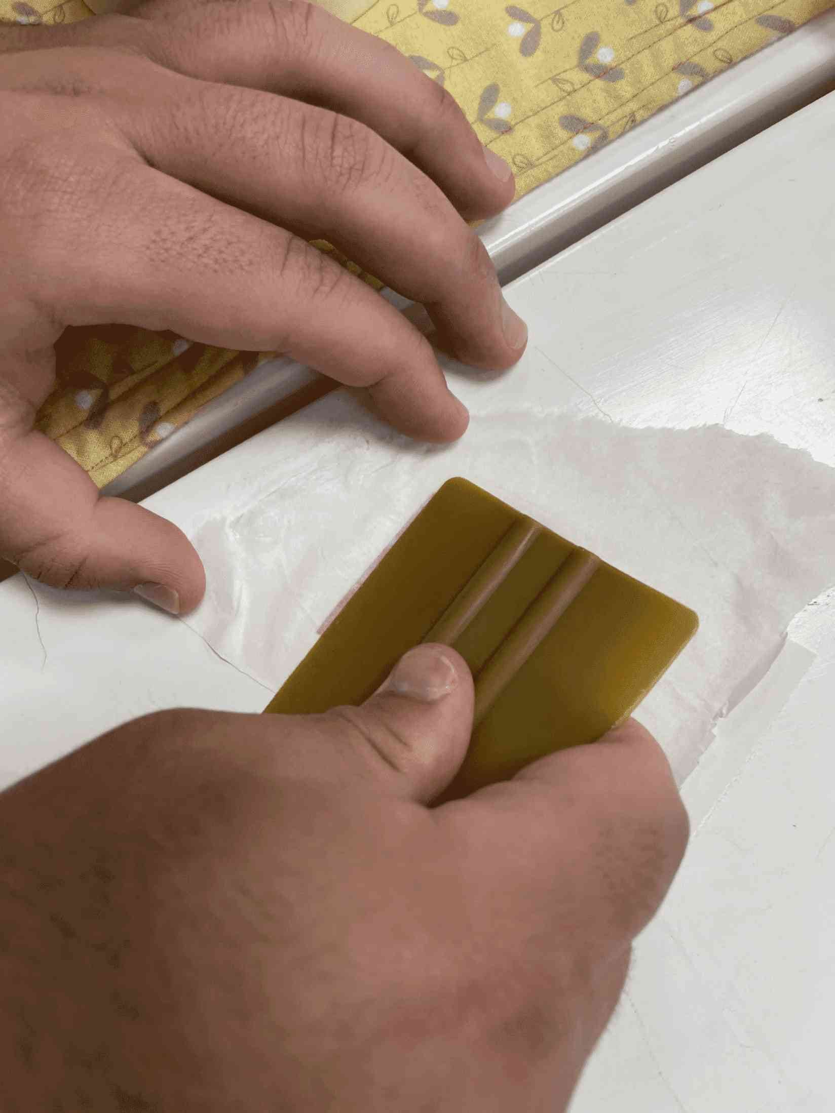
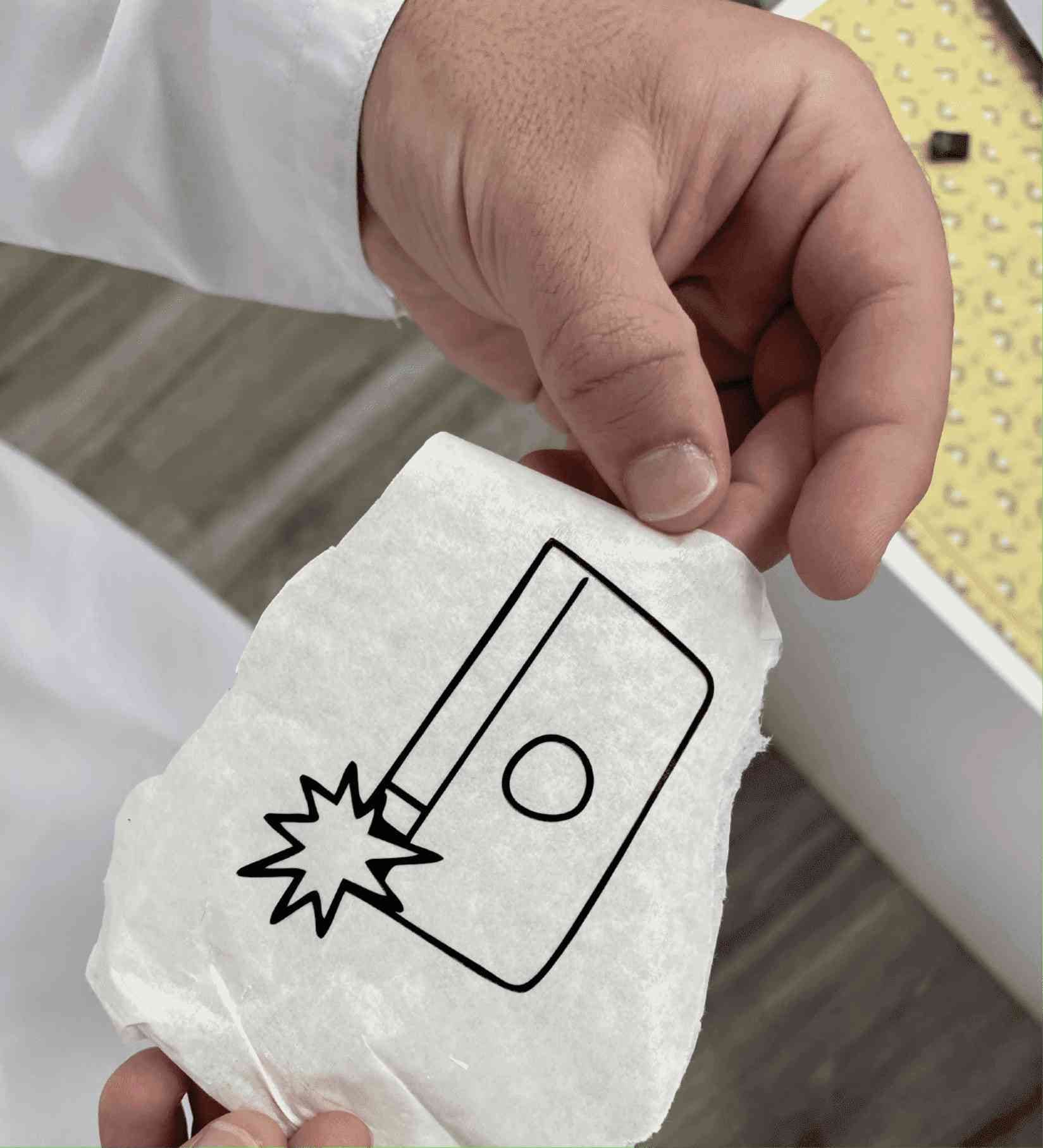
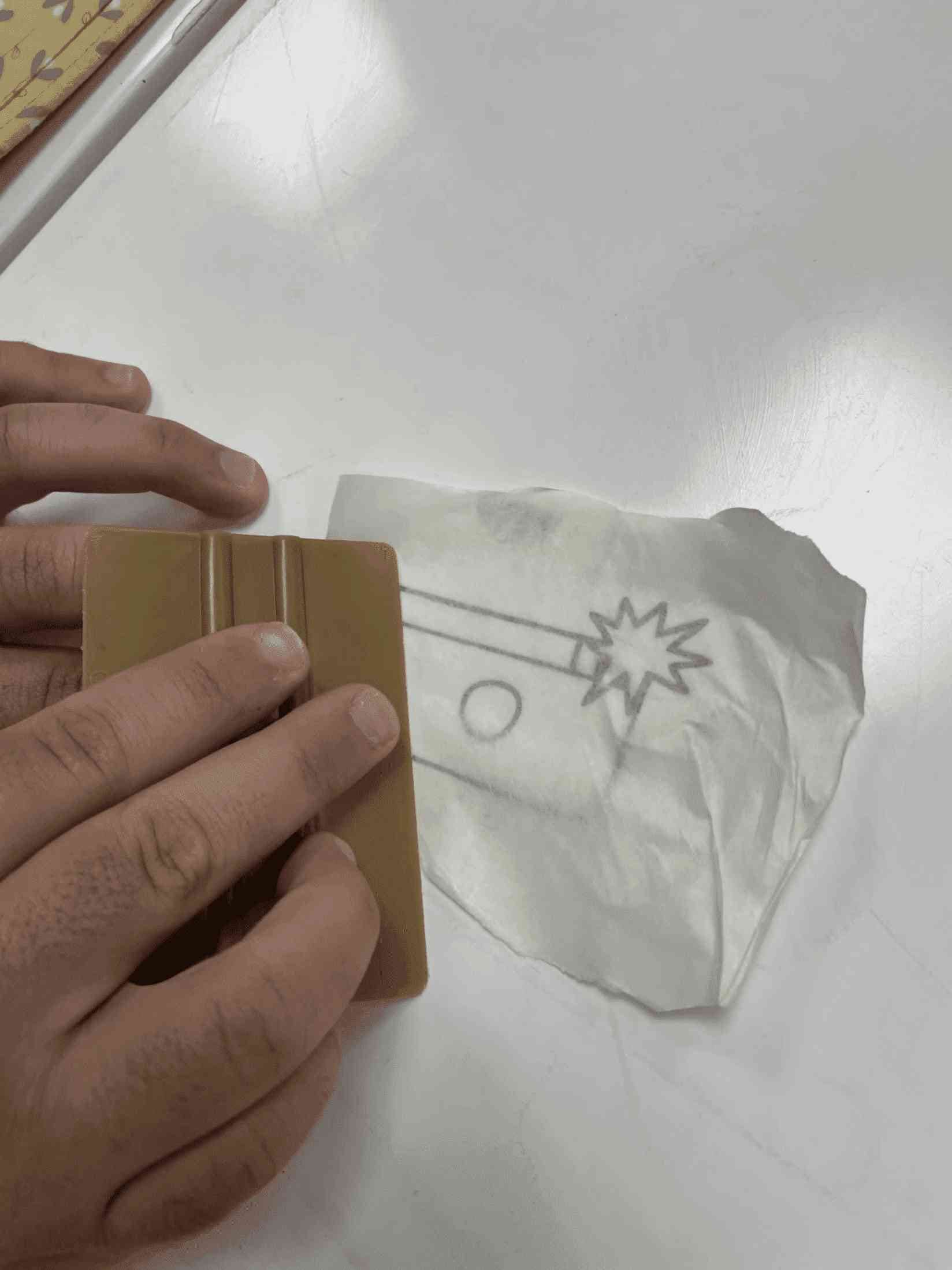
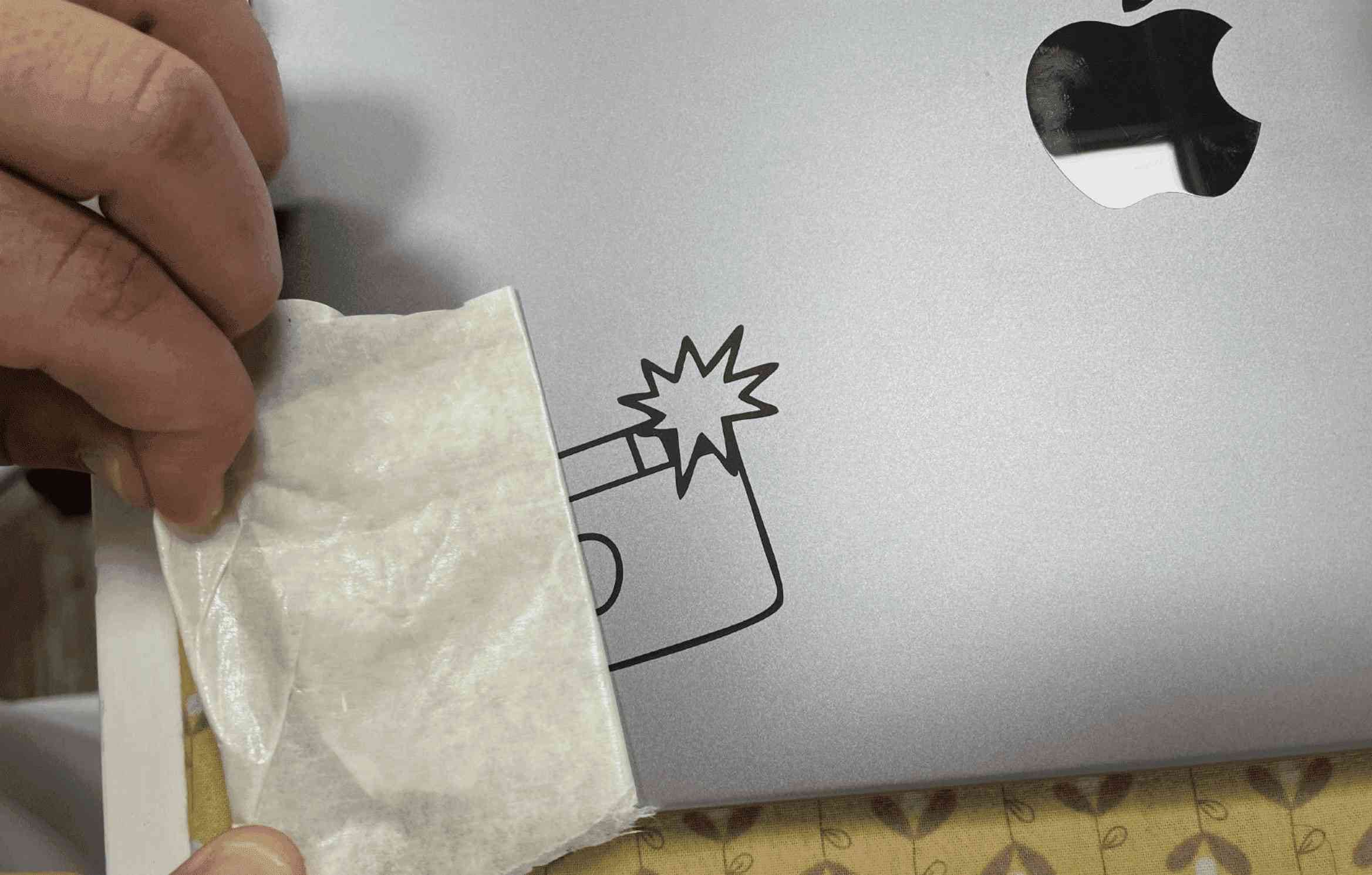
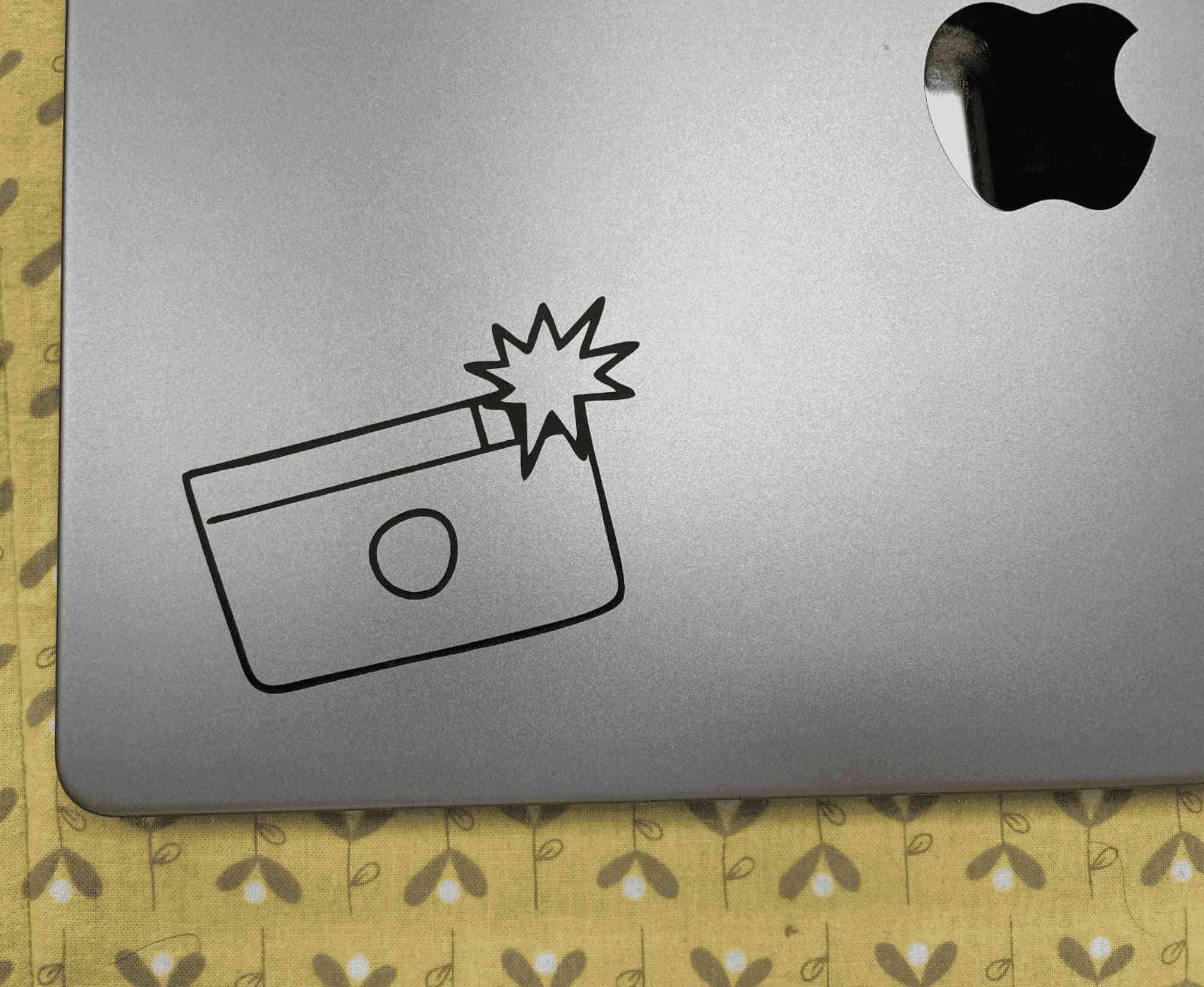
Now is the time to prepare the sticker as shown in the images below:
Bonus use (Multi -colors) in a sticker:
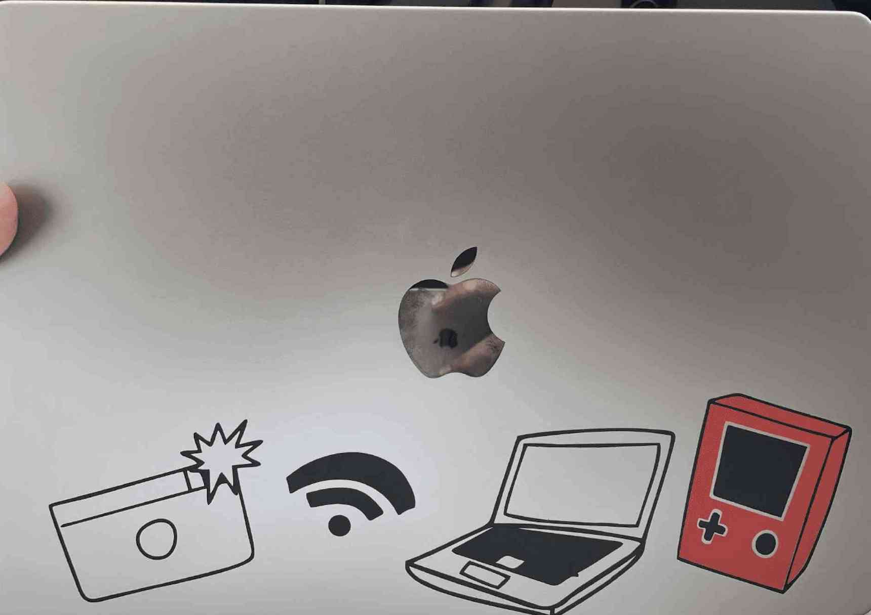
For this task, I used the same method of cutting stickers in one color, but the process was more complicated, as I cut the same sticker twice, each time with a different color, and placed the sticker on top of each other after getting rid of unwanted labels.
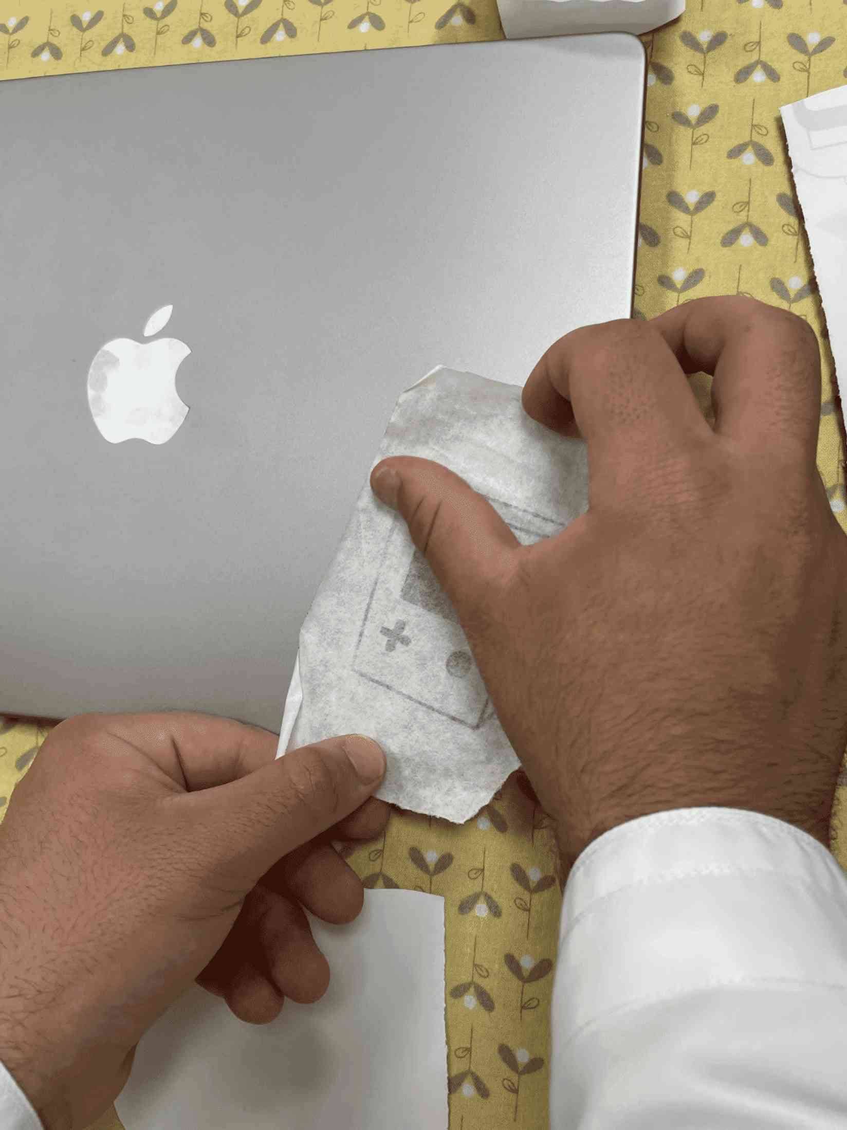
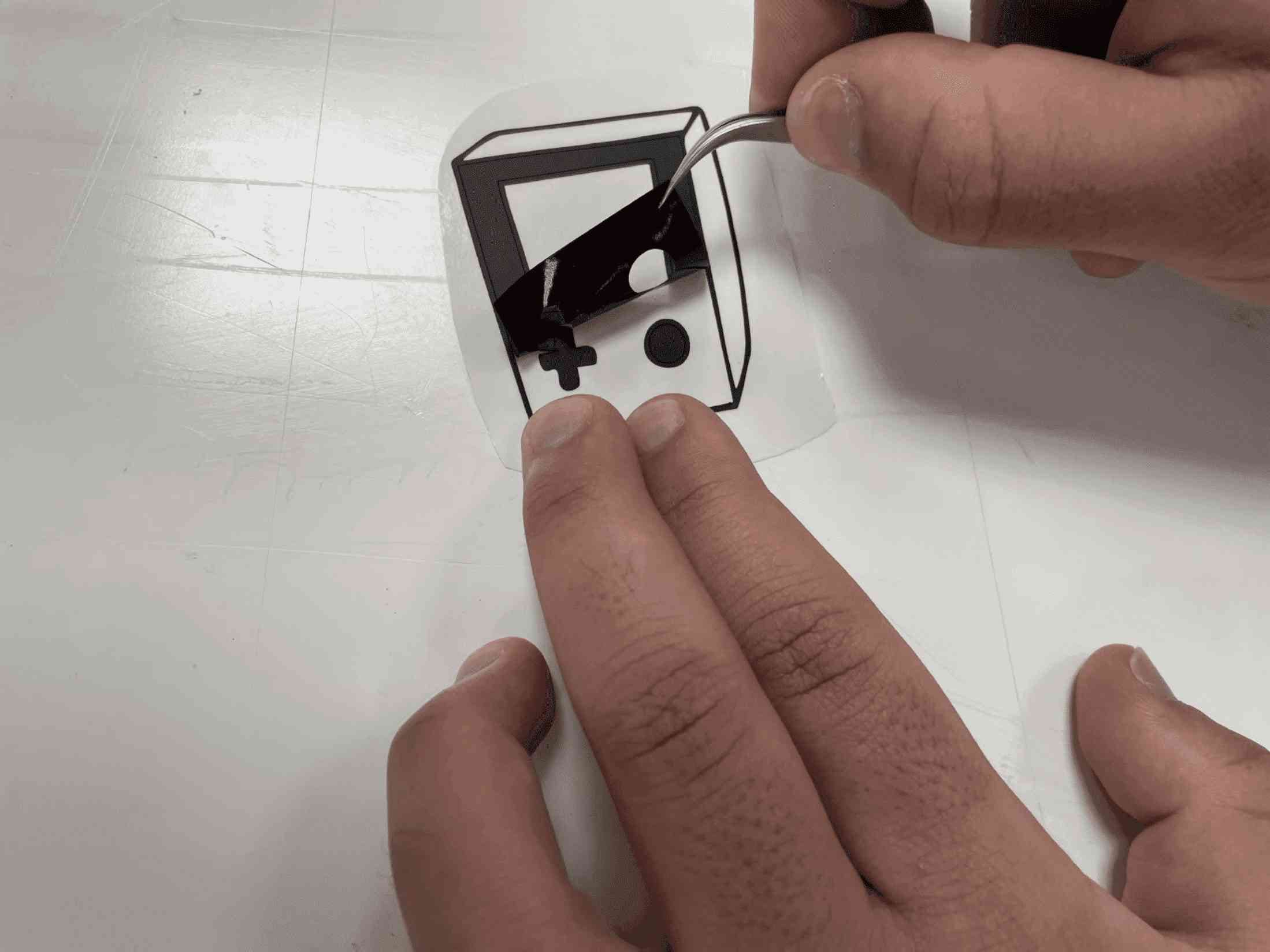
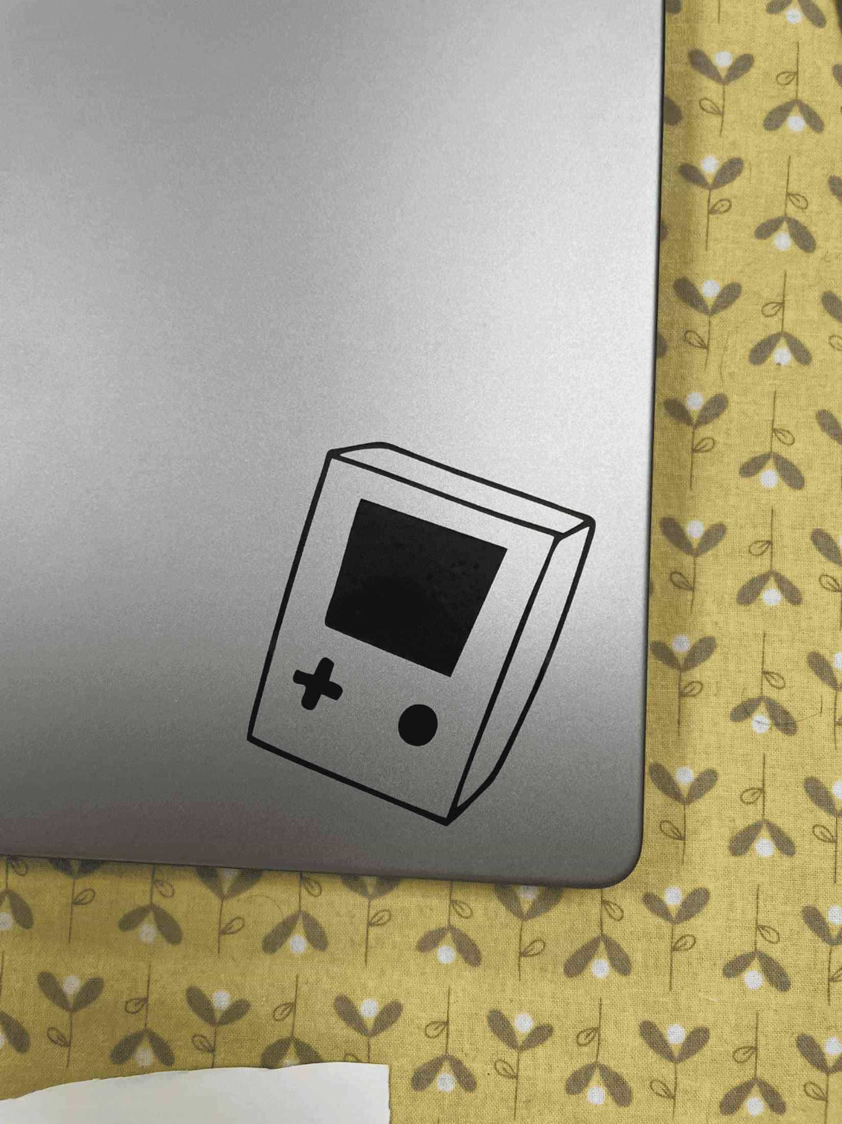
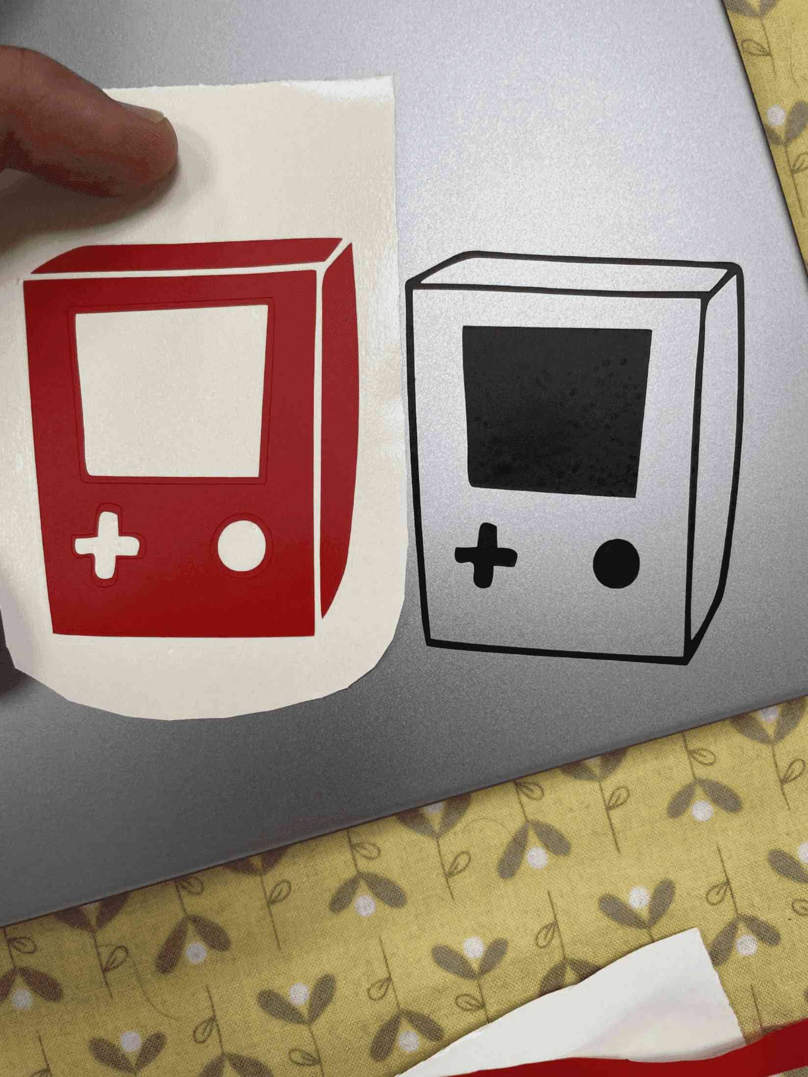
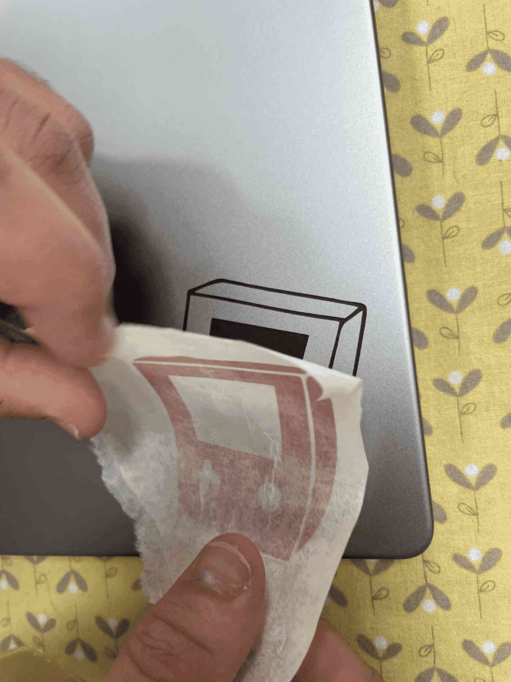
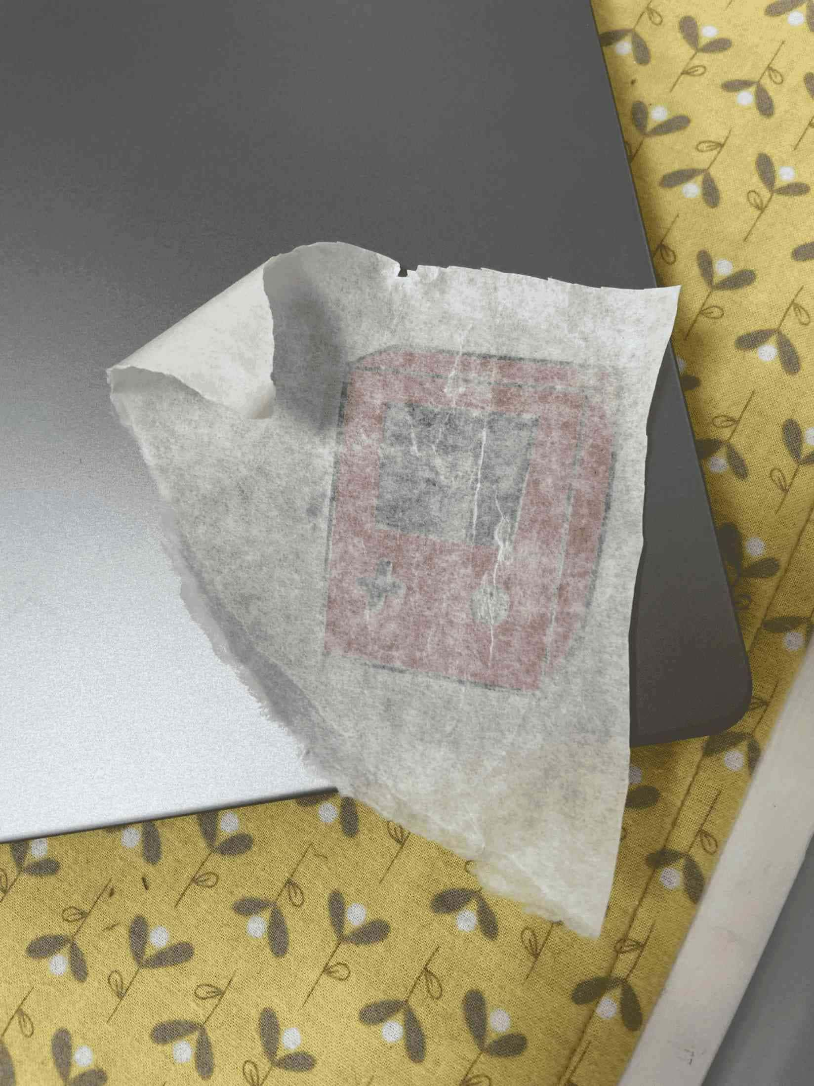
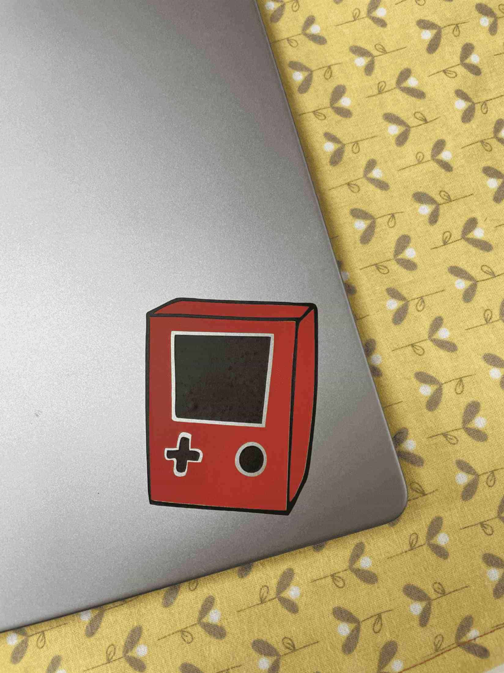
The final look of the sticker shown below:
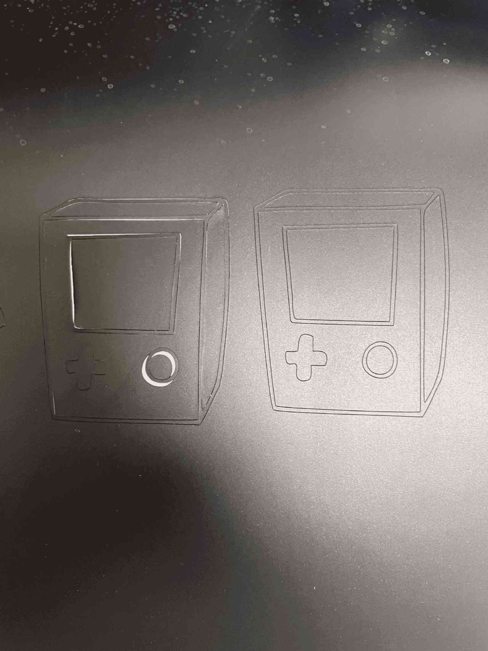
Problem:
I face some problems even after testing the rigth force, But I discovered that the empty spaces in some of the images were not empty, but were in white, so I emptied all the white spaces, and the result was clear and impressive.
Cast Acrylic 3mm - Abdalla:
I select: Plastic (Cast Acrylic 3mm) color orange

1. For power, speed ,and, rate: cutting and engrave any shape:
I created a circle in CorelDRAW and wrote my name inside it to test cutting and engraving. Furthermore, I chose the square outline to be 'red' in order to cut it, and I also had to choose the line type to be a hairline because the Universal Laser cutter PSL6MW) understands and uses red for cutting and black for engraving. On the other hand, I chose the name in 'black' for the engraving.
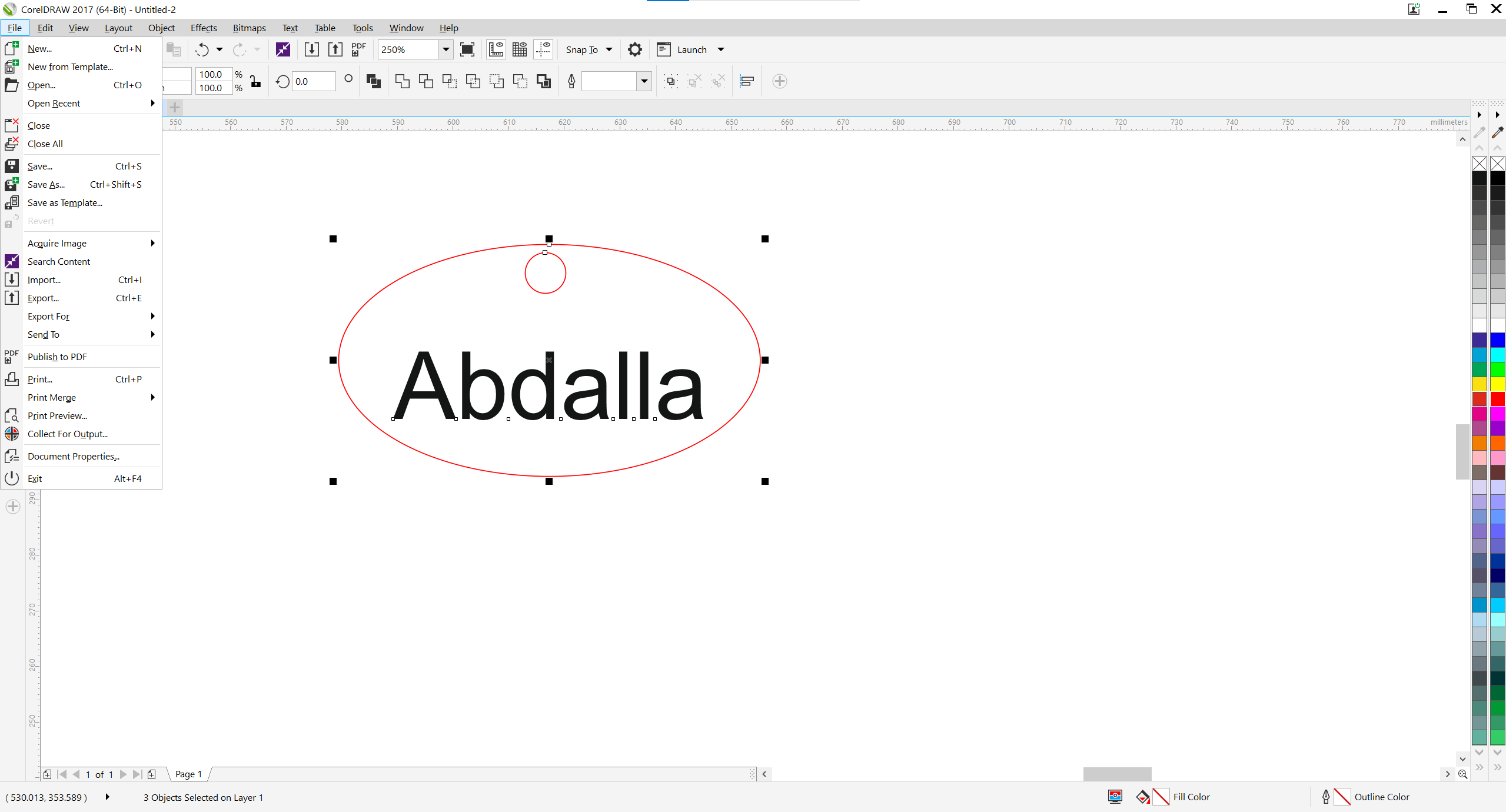
Select File >> Print >> Preferences >> next. The control panel for Universal Laser Systems will appear, allowing you to add the machine's settings.
We measure the thickness with a digital caliper from all sides and then take the average. I discovered that the thickness was 3.08 mm, thus it is crucial to add the correct thickness of material to avoid errors when cutting.
Even though the manufacturer is aware of the material's thickness, we still need to measure it to rule out any errors.
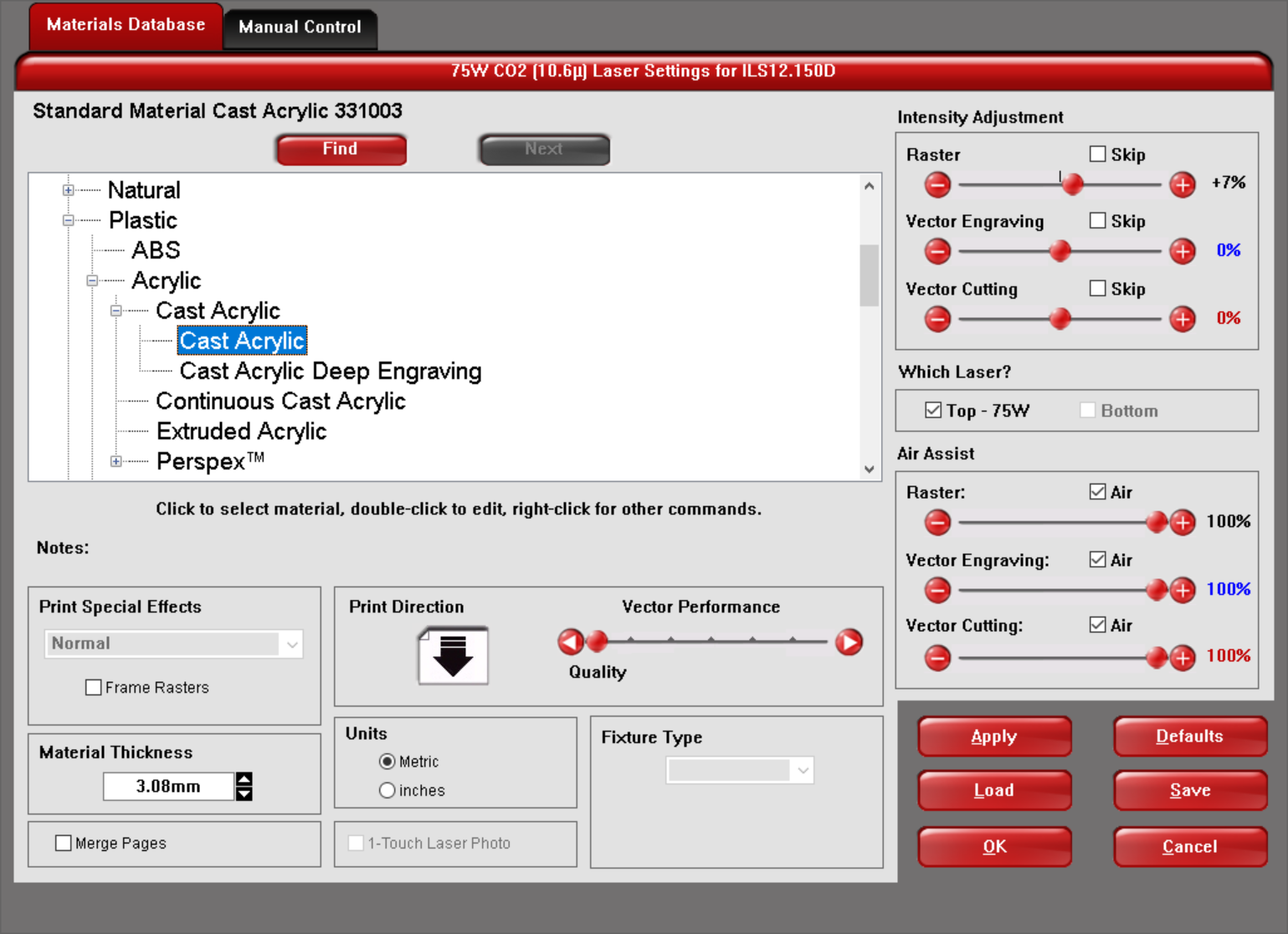

As shown above first for Material Database I select plastic >> Cast Acrylic, also I entered the material thickness 3.08 mm >> then press "Apply".
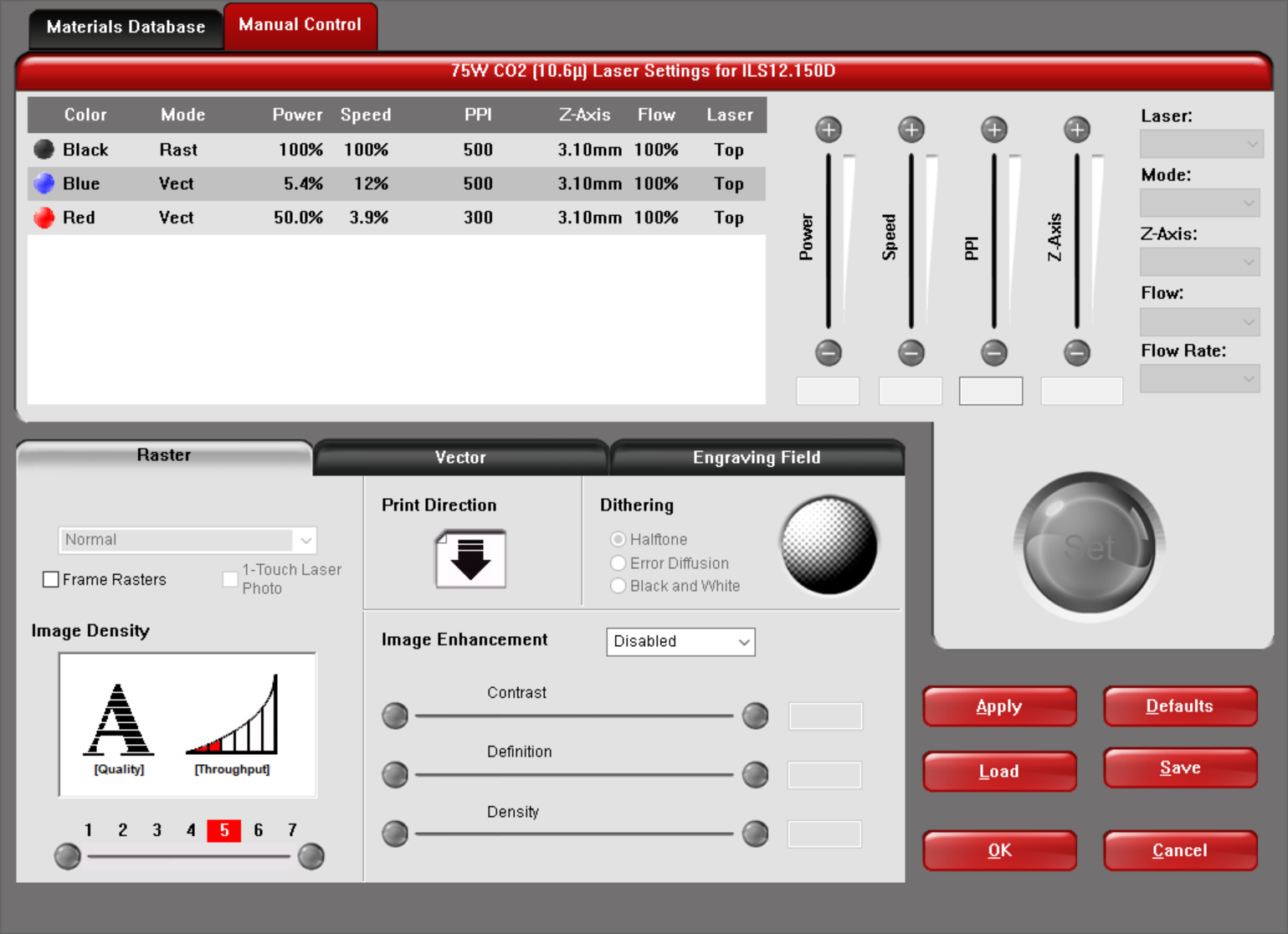
Manual control Red color for Cutting: (Failed )
Power : 50%
Speed: 3.9%
PPI: 300
Manual control black color for Cutting: (Failed )
Power : 100%
Speed: 100%
PPI: 500
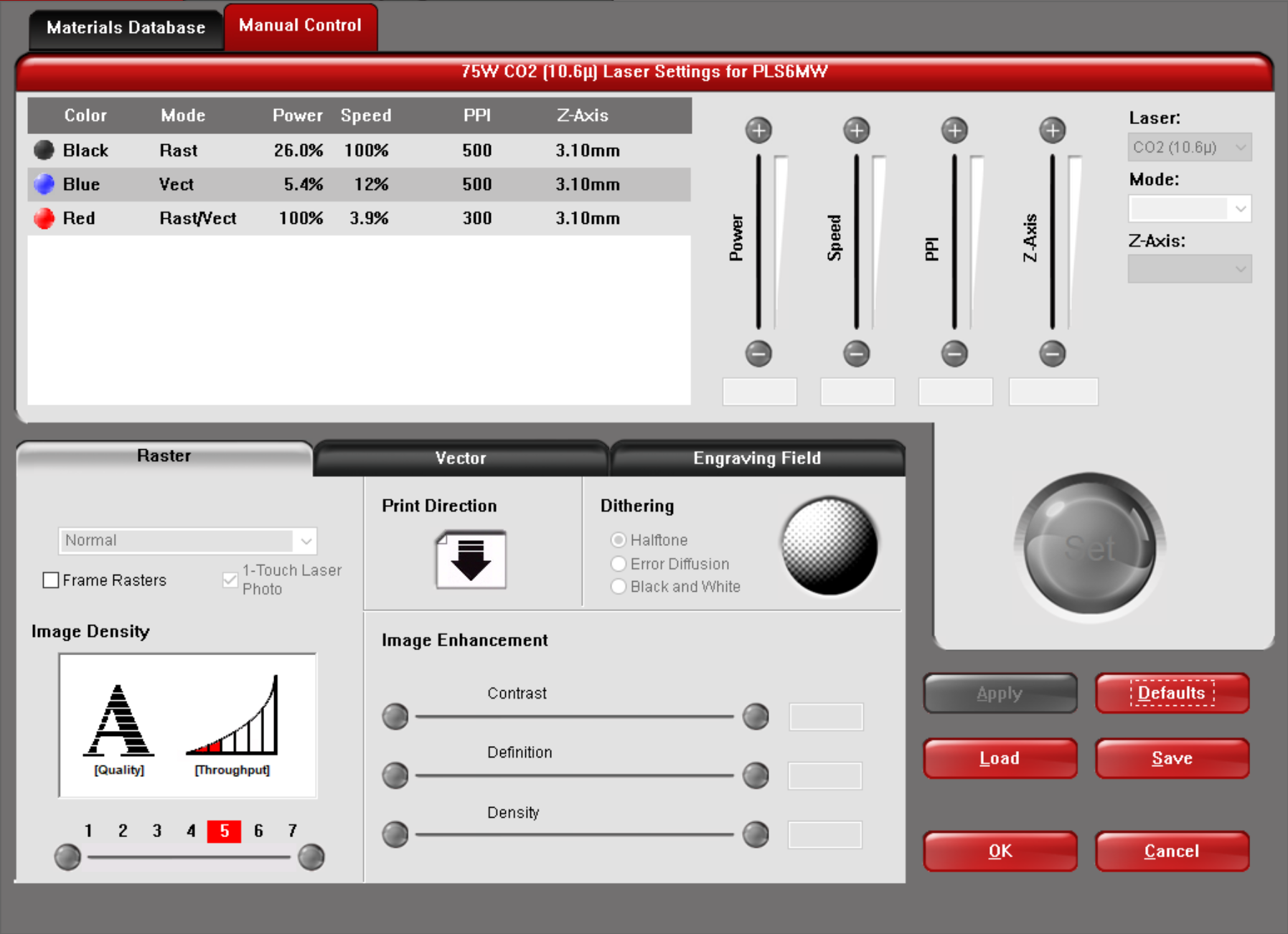
Manual control Red color for Cutting: (Pass )
Power : 100%
Speed: 3.9%
PPI: 1000
Manual control black color for Cutting: (Pass )
Power : 100%
Speed: 26%
PPI: 500
The image below shown the laser cutting for the mention settings above ::

2. Calculate the kerf:
Kerf is the width of material that is removed by a cutting process. For the kerf calculation, I did create rectangular (80x30 mm) and section it to 10 non equal parts we can have more sections, increasing the sections number will make the calculation more accurate. Afterward, I used Digital Caliper to measure the length after cutting in order to find the kerf.


I found the kerf of Cast Actylic = 0.167 mm using the equaiton below:
kerf= (Theroetical length - Measured length) / # of sections
kerf= (80 - 78.33)/10 = 0.167 mm